1
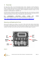
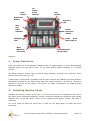
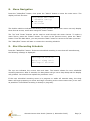
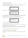
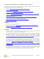
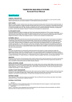
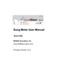
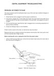
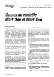
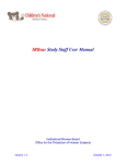
TERN Australian SuperSite Network Acoustic Sensor User Guide Nov 2013 Table of Contents 1. Overview .................................................................................................................................................... 1 2. Power Resources ........................................................................................................................................ 2 3. Installing Memory Cards ............................................................................................................................ 2 4. Installing Microphones............................................................................................................................... 3 5. Mounting the Sensor.................................................................................................................................. 3 6. Switching the Sensor ON and OFF.............................................................................................................. 3 7. Sensor Configuration.................................................................................................................................. 3 8. Menu Navigation ........................................................................................................................................ 4 9. Start Recording Schedule ........................................................................................................................... 4 10. Making Recordings................................................................................................................................... 5 11. Aborting a Recording in Progress............................................................................................................. 5 12. Manual Recording Feature ...................................................................................................................... 6 13. Transferring Data ..................................................................................................................................... 6 14. Solar Configuration for TERN Acoustic Sensor......................................................................................... 7 15. Pre-Deployment Checklist........................................................................................................................ 9 1. Overview The Song Meter SM2+ is an environmental acoustic sensor, designed to remain deployed in the field recording continuously for extended periods of time. The Sensor cover, when properly closed, is weather-tight and vented to protect against condensation and stress on seals caused by pressure changes. While it is designed to survive temporary immersion in water, it is not designed or recommended for underwater use. All of the sensors electronics, batteries, data storage flash cards, and controls are mounted inside the enclosure to protect them from the elements, and are therefore inaccessible without removing the enclosure’s cover. Figure 2 illustrates the inside of the sensor. For comprehensive instructions please consult the http://www.wildlifeacoustics.com/ and the Song Meter User Manual at: website http://www.wildlifeacoustics.com/images/documentation/SM2plus1.pdf Removing and Replacing the Cover There are four plastic cover screws in the corners. These screws have clips to prevent them from falling out and getting lost. When closing the cover make sure the indicator LED window is correctly oriented over the LED on the circuit board and tighten the screws by turning them clockwise. The foam insert on the inner side of the lid is to prevent battery movement. Left Mic Input Right Mic Input External Power Input Pressure Equalization Vent Cable Gland Figure 1 Acoustic Sensor User Guide (Version 2, November 2013) Page | 1 Back Button Up Select Down Buttons Wake/Exit Button LCD Display Indicator LED Amp and Filter Switches Power Selection Switch Headphone Jack Flash Card Slots A,B,C,D Main Batteries 4 D-Cells) Clock Batteries (2 AA-Cells) Figure 2 2. Power Resources Each unit requires 4 D cell batteries. Batteries last for approximately 14 days. Rechargeable batteries have very high failure rates, so use good quality alkaline batteries (i.e. Duracell Procell). The Power Selection Switch can be used to select between “internal” and “external” power sources and to turn the unit “off”. A solar power configuration is possible and has been used at Alice Mallee and Great Western Woodlands SuperSites have been fitted with solar panels allowing 3 months of continuous operation (using 64 Gb SD cards). See section 14. Solar Configuration for TERN Acoustic Sensor for details. 3. Installing Memory Cards Standard SD memory cards can be used. The four card slots can be populated with one to four flash cards of assorted capacities. Acoustic monitors supplied to SuperSites were initially supplied with 32 Gb SD Cards. These can be replaced with higher capacity SD cards if necessary. You must install at least one flash card in order for the Song Meter to make and store recordings. Acoustic Sensor User Guide (Version 2, November 2013) Page | 2 4. Installing Microphones The SMX-II weather-proof microphones can attach directly to the left and right microphone input connectors on the Song Meter. Alternatively, they can be extended on cables. Note that the microphones are fragile - they should be removed from the Song Meter during transport. The microphones, while weather-proof, are expected to degrade over time. It is recommended that recording quality is checked every 6 months and microphone replacement considered. Replacement SMX-II weather-proof microphones can be ordered from: . http://www.wildlifeacoustics.com/buy ($70 USD each + Delivery $96.68 USD as of Nov 2013). 5. Mounting the Sensor Where practical, the sensors should be deployed at roughly chest height on a star picket in the centre of the core 1ha plot. Please also refer to the pre-deployment checklist on page 9 before deploying. 6. Switching the Sensor ON and OFF To switch the Sensor On/Off press the “Wake/Exit” button (see Figure 2). When the Sensor is switched on, the display will look something like this: 2012-Sep-16 13:32:56 Song Meter II R3.1.0 A: 32G 48%B: 32G 0% C: N/A D: N/A The top row displays the current date and time and is updated every second. The bottom two rows display the status of the four SD card slots labelled “A” through “D”. If no SD card is plugged into a slot, “N/A” is displayed to indicate that the slot is not available. 7. Sensor Configuration The sensors have been pre-configured to record for 12 hours per day (6 hours around dawn and 6 hours around dusk). They will adjust themselves to record at the correct time throughout the year using the GPS coordinates of the individual sites. Configured to record 12 hours per day, the units will run for approximately 14 days before running out of battery power. At this point, the batteries will need to be replaced and the data should be transferred from the SD cards. If the sensors require reconfiguring, please consult Jason Wimmer, Queensland University of Technology ([email protected]), as configuration files can be stored and sent on a SD card for uploading on the unit, obviating the need to do this manually. For more details on configuration see pp 15-42: http://www.wildlifeacoustics.com/images/documentation/SM2plus1.pdf Acoustic Sensor User Guide (Version 2, November 2013) Page | 3 8. Menu Navigation Press the “Wake/Exit” button, then press the “Select” button to enter the main menu. The display will look like this: Song Meter Main Menu - Schedule (daily) - Settings - Utilities The double underline indicates the blinking cursor position. Each menu screen can only display three lines at a time, scroll down using the “Down” button. The “Up” and “Down” buttons can be used to scroll through the menu choices. To select a menu choice, press the “Select” button. To return to the previous menu, press the “Back” button. From the Main Menu, you can press the “Back” button to return to the start-up screen. The “Wake/Exit” button will start or resume the recording schedule. 9. Start Recording Schedule Press the “Wake/Exit” button. If the next scheduled recording is more than 45 seconds away, the following message is displayed: 2012-Sep-16 13:34:12 Going to sleep until 2011-Sep-17 05:30:00 The top row indicates the current time and date. The bottom shows the next scheduled recording start time. After 5 seconds, the Song Meter will go into a deep sleep and the display will go blank. You should now replace the protective cover. If the next scheduled recording event is in progress or within 45 seconds away, the Song Meter will begin preparing to record and begin recording at the correct start time (or as soon as possible if a scheduled recording is already in progress). Acoustic Sensor User Guide (Version 2, November 2013) Page | 4 10. Making Recordings Once configured, pressing the “Wake/Exit” button will cause the Sensor to put itself to sleep until the next scheduled recording event. The Sensor will automatically wake up about 30 seconds before the scheduled event. 2012-Sep-16 13:32:56 Song Meter II R3.1.0 A: 32G 48%B: 32G 0% C: N/A D: N/A After scanning the four SD flash card slots, the message “Preparing to record” will appear: 2012-Sep-16 05:29:11 Song Meter II R3.1.0 Preparing to record Note that if a scheduled recording time is already in progress, the Sensor will begin recording as soon as it is ready to do so and end the recording on schedule. You can abort the next recording and return to the main menu by pressing the “Wake/Exit” button. When the Sensor begins recording, the display will indicate progress as shown below: 2012-Sep-16 13:32:56 Recording: 01:29:12 B:0909111332.WAV 0% 44100xStereo 5% The top line of the display shows the current date and time as before. The second line indicates the time remaining in the current recording. The third line shows the flash card slot and short file name of the recording file (MMDDhhmm.WAV) and the percentage completed. The last line shows the sample rate and number of channels (x2 for stereo, x1 for mono), and the percentage indicates how full the SD flash card slot is on which the recording is being made. You can press the “Select” button to toggle between the displays. 11. Aborting a Recording in Progress While the Sensor is recording, you can press the “Back” or “Wake/Exit” to abort the recording in progress. Acoustic Sensor User Guide (Version 2, November 2013) Page | 5 12. Manual Recording Feature In addition to recording on a schedule, the Sensor can also start a recording when the start-up screen is displayed by pushing the “Up” and “Down” buttons simultaneously. This will start a one-hour recording on the lowest lettered slot on which the recording will fit. Pressing the “Select” button toggles between display modes and headphone. 13. Transferring Data Data should be transferred from the SD cards to the 1TB external USB drive. Once the data has been successfully transferred from the SD cards to the external drive, please delete the data from the SD card, re-insert it in the sensor and redeploy. Please return the external USB drives to the address below every three months to have the data uploaded to the central repository. Please also keep a copy of all the data stored on the external drive in case it fails or is lost in the post. Once the data has been uploaded, the external USB hard drives will be returned. Ultimately the data will be available for online analysis. See www.bush.fm. Jason Wimmer eResearch Queensland University of Technology Level 10 1006 S Block Gardens Point Campus 2 George Street Brisbane QLD 4000 The external drives are USB 3.0 compatible, so if possible use a computer with a USB 3.0 port to save time transferring the data. Otherwise, downloading takes approximately 1 minute per GB. Acoustic Sensor User Guide (Version 2, November 2013) Page | 6 14. Solar Configuration for TERN Acoustic Sensor The solar power setup comprises a deep cycle 12 volt battery, charge controller, solar panel, pole mount and SM2 external power adapter cable. Battery: http://www.apolloenergy.com.au/Renewable-EnergyComponents/Batteries/N50-GEL Charge Controller: http://www.apolloenergy.com.au/Renewable-EnergyComponents/Charge-Controllers/SS-10L-12V Solar Panel: http://www.apolloenergy.com.au/Renewable-Energy-Components/Browseby-Manufacturer-Suntech/STP020S-12-Cb Solar Panel Pole Mount: http://www.greensystems.com.au/products/product.php?prod_code=GS-MNT-02 SM2 (acoustic sensor) external power adapter cable: http://www.wildlifeacoustics.com/wa-php/order.php#power and http://faunatech.com.au/ You need: 2 x star pickets (preferably 240 cm) Battery box similar to this http://www.jpwmarine.com.au/products/electrical/batteryboxes/battery-box-standard-size.aspx Multimeter (http://www.jaycar.com.au/productView.asp?ID=QM1500) Installation: 1. The entire setup is not particularly bulky, but the battery weighs about 24 kg, so vehicular access to the site would be an advantage. 2. The solar panel pole mount can be mounted on a star picket. The mount has been designed to accept the Suntech 20 W solar panel without any modification, but please test both mounting of the solar panel and attaching to a star picket beforehand http://www.greensystems.com.au/files/pdf/products/GS-MNT-02_pdf.pdf. There may be some slight modifications required. 3. Some wiring will be required when deploying the solar setup to connect the solar panel to the charge controller, charge controller to the battery and sensor. This will require a screw driver, pliers and wire strippers. If possible bring a multimeter with you as well, for fault finding (http://www.jaycar.com.au/productView.asp?ID=QM1500). Instructions for the charge controller are included here: http://www.apolloenergy.com.au/core/media/media.nl/id.245333/c.851604/.f?h=9667c2 23a94e62fe2322 4. The solar panel should be mounted on a star picket and oriented to the north at an angle of approximately 30 degrees (Figure 3). The solar panel should be mounted on another star picket next to this, with the battery and charge controller in between. Acoustic Sensor User Guide (Version 2, November 2013) Page | 7 Figure 3 5. The battery and charge controller are fairly robust, but should be kept off the ground and out of direct sunlight. Try using plastic marine battery enclosures like this: http://www.jpwmarine.com.au/products/electrical/battery-boxes/battery-box-standardsize.aspx Use a couple of house bricks to keep them off the ground. Also sprinkle ant granules in the bottom to keep the ants away. 6. If you have any cattle or other curious animals, you may need to consider a little electric fence setup, such as: http://www.sureguard.com.au/products/Farm-ElectricFencing/Portable-Budget-Electric-Fence-12-Volt The solar configuration selected should support this, but you may need to increase the solar panel size to 40W. 7. In terms of maintenance, give the solar panel a wipe and check the cables for damage when you change the SD cards. Sensor Setup: 1. Attach the SM2 external power adapter to the SM2 external power input (below the lefthand microphone input). See page 2 http://www.wildlifeacoustics.com/wpcontent/uploads/2011/08/SM2plus1.pdf 2. Switch the SM2 from internal to external power using the power selection switch. See page 4 and page 10 http://www.wildlifeacoustics.com/wpcontent/uploads/2011/08/SM2plus1.pdf 3. When connected to the battery, the unit should power up as normal. Acoustic Sensor User Guide (Version 2, November 2013) Page | 8 15. Pre-Deployment Checklist 1. Inspect the Sensor for damage inside and out. Verify that the three input connector nuts (left and right microphone inputs and external power input) are finger tight and that the weatherproof vent is also finger tight by turning clockwise. Never turn the nuts or vent counter-clockwise. Also verify that the cable gland is well seated and not punctured. 2. Install four fresh high-quality alkaline batteries in the main battery tray. Always remove flash cards prior to inserting or removing batteries to avoid damage to the card connectors. 3. Test and replace the 2 AA clock batteries annually. 4. Check to make sure that the date and time are set correctly and the clock is running. 5. Check to make sure you (http://www.wildlifeacoustics.com/). 6. Check the Zorb-It® packet installed on the inside cover. If it is noticeably swollen, it may have been exposed to liquid water and should be replaced. For more information, visit www.zorb-it.com. 7. After installing flash cards and microphones, use the instant record feature to make a test recording, and listen to the test recording to verify your audio settings are set as intended. See “Manual Recording Feature” on page 6. 8. In hot environments, avoid exposing the Sensor to direct sunlight to ensure that the inside temperature does not exceed the rated limits of the Sensor or batteries. 9. When you put the Sensor to sleep with the Wake/Exit button, make sure it indicates the expected wake-up time. 10. Make sure the indicator LED is flashing once per minute when sleeping or once per second while recording before walking away. have the latest version Acoustic Sensor User Guide (Version 2, November 2013) of firmware Page | 9