1
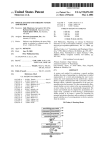
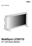
CAUTION:
Use of controls, adjustments or procedures other than those specified herein may result in
hazardous radiation exposure.
CA UTION: TO REDUCE THE RISK OF
ELECTRICAL SHOCK, DO NOT REMOVE
COVER (OR BACK). NO USER SERVICEABLE
PARTS INSIDE. REFER SER VICING TO
QUALIFIED SERVICE PERSONNEL.
CAUTION
RISK OF ELECTRIC
ELECTRIC
SHOCK DO NOT OPEN.
The lighting flash with arrowhead symbol, with an equilateral triangle is intended to
alert the user to the presence of uninsulated dangerous voltage within the products
enclosure that may be of sufficient magnitude to constitute a risk of electric shock to
the person.
The exclamation point within an equilateral triangle is intended to alert the user to the
presence of important operating and maintenance (servicing) instructions in the
literature accompanying the appliance.
WARNING: TO REDUCE RISK OF FIRE OR ELECTRIC SHOCK, DO NOT
EXPOSE THIS APPLIANCE TO RAIN OR MOISTURE.
2
IMPORTANT SAFETY INSTRUCTIONS
CAUTION:
Read all of these instructions. Save these instructions for later use. Follow all Warnings and
Instructions marked on the audio equipment.
1. Read Instructions- All the safety and operating instructions should be read before the product is operated.
2. Retain Instructions- The safety and operating instructions should be retained for future reference.
3. Heed Warnings- All warnings on the product and in the operating instructions should be adhered to.
4. Follow Instructions- All operating and use instructions should be followed.
FOR YOUR PERSONAL SAFETY
1.
When the power cord or plug is damaged or frayed, unplug this television set from the wall outlet and refer servicing to
qualified service personnel.
2.
Do not overload wall outlets and extension cords as this can result in fire or electric shock.
3.
Do not allow anything to rest on or roll over the power cord, and do not place the TV where power cord is subject to
traffic or abuse. This may result in a shock or fire hazard.
4.
Do not attempt to service this television set yourself as opening or removing covers may expose you to dangerous
voltage or other hazards. Refer all servicing to qualified service personnel.
5.
Never push objects of any kind into this television set through cabinet slots as they may touch dangerous voltage
points or short out parts that could result in a fire or electric shock. Never spill liquid of any kind on the television set.
6.
If the television set has been dropped or the cabinet has been damaged, unplug this television set from the wall outlet
and refer servicing to qualified service personnel.
7.
If liquid has been spilled into the television set, unplug this television set from the wall outlet and refer servicing to
qualified service personnel.
8.
Do not subject your television set to impact of any kind. Be particularly careful not to damage the picture tube surface.
9.
Unplug this television set from the wall outlet before cleaning. Do not use liquid cleaners or aerosol cleaners. Use a
damp cloth for cleaning.
10.1. Do not place this television set on an unstable cart, stand, or table. The television set may fall, causing serious injury
to a child or an adult, and serious damage to the appliance. Use only with a cart or stand recommended by the
manufacturer, or sold with the television set. Wall or shelf mounting should follow the manufacturer s instructions, and
should use a mounting kit approved by the manufacturer.
10.2. An appliance and cart combination should be moved with care. Quick stops, excessive force, and uneven surfaces
may cause the appliance and cart combination to overturn.
3
PROTECTION AND LOCATION OF YOUR SET
11.
Do not use this television set near water ... for example, near a bathtub, washbowl, kitchen sink, or laundry tub, in a
wet basement, or near a swimming pool, etc.
Never expose the set to rain or water. If the set has been exposed to rain or water, unplug the set from the wall
outlet and refer servicing to qualified service personnel.
12. Choose a place where light (artificial or sunlight) does not shine directly on the screen.
13. Avoid dusty places, since piling up of dust inside TV chassis may cause failure of the set when high humidity persists.
14. The set has slots, or openings in the cabinet for ventilation purposes, to provide reliable operation of the receiver, to
protect it from overheating. These openings must not be blocked or covered.
Never cover the slots or openings with cloth or other material.
Never block the bottom ventilation slots of the set by placing it on a bed, sofa, rug, etc.
Never place the set near or over a radiator or heat register.
Never place the set in a built-in enclosure, unless proper ventilation is provided.
PROTECTION AND LOCATION OF YOUR SET
15.1. If an outside antenna is connected to the television set, be sure the antenna system is grounded so as to provide some
protection against voltage surges and built up static charges, Section 810 of the National Electrical Code, NFPA No.
70-1975, provides information with respect to proper grounding of the mast and supporting structure, grounding of the
lead-in wire to an antenna discharge unit, size of grounding conductors, location of antenna discharge unit, connection
to grounding electrode, and requirements for the grounding electrode.
EXAMPLE OF ANTENNA GROUNDING AS PER NATIONAL ELECTRICAL CODE INSTRUCTIONS
EXAMPLE OF ANTENNA GROUNDING AS PER
NATIONAL ELECTRICAL CODE
ANTENNA
LEAD- IN WIRE
GROUND CLAMP
ANTENNA DISCHARGE
UNIT (NEC SECTION
810-20)
GROUNDING
CONDUCTORS
(NEC SECTION 810-21)
ELECTRIC SERVICE
EQUIPMENT
GROUND CLAMPS
POWER SERVICE GROUNDING
ELECTRODE SYSTEM
(NEC ART 250. PART H)
NEC-NATIONAL ELECTRICAL CODE
15.2. Note to CATV system installer : (Only for the television set with CATV reception)
This reminder is provided to call the CATV system installer s attention to Article 820-40 of the NEC that provides
guidelines for proper grounding and, in particular, specifies that the cable ground shall be connected to the grounding
system of the building, as close to the point of cable entry as practical.
16.
An outside antenna system should not be located in the vicinity of overhead power lines or other electric lights or power
circuits, or where it can fall into such power lines or circuits. When installing an outside antenna system, extreme care
should be taken to keep from touching such power lines or circuits as contact with them might be fatal.
17.
For added protection for this television set during a lightning storm, or when it is left unattended and unused for long
periods of time, unplug it from the wall outlet and disconnect the antenna. This will prevent damage due to lightning
and power-line surges.
4
OPERATION OF YOUR SET
18.
This television set should be operated only from the type of power source indicated on the marking label. If you are not
sure of the type of power supply at your home, consult your television dealer or local power company. For television
sets designed to operate from battery power, refer to the operating instructions.
19.
If the television set does not operate normally by following the operating instructions, unplug this television set from the
wall outlet and refer servicing to qualified service personnel. Adjust only those controls that are covered in the operating
instructions as improper adjustment of other controls may result in damage and will often require extensive work by a
qualified technician to restore the television set to normal operation.
20.
When going on a holiday : If your television set is to remain unused for a period of time, for instance, when you go on
a holiday, turn the television set off and unplug the television set from the wall outlet.
IF THE SET DOES NOT OPERATE PROPERLY
21. If you are unable to restore normal operation by following the detailed procedure in your operating instructions,
do not attempt any further adjustment. Unplug the set and call your dealer or service technician.
22. Whenever the television set is damaged or fails, or a distinct change in performance indicates a need for
service, unplug the set and have it checked by a professional service technician.
23. It is normal for some TV sets to make occasional snapping or popping sounds, particularly when being
turned on or off. If the snapping or popping is continuous or frequent, unplug the set and consult your
dealer or service technician.
FOR SERVICE AND MODIFICATION
24. Do not use attachments not recommended by the television set manufacturer as they may cause hazards.
25. When replacement parts are required, be sure the service technician has used replacement parts specified
by the manufacturer that have the same characteristics as the original part. Unauthorized substitutions
may result in fire, electric shock, or other hazards.
26. Upon completion of any service or repairs to the television set, ask the service technician to perform
routine safety checks to determine that the television is in safe operating condition.
5
PFS2 FORMAT-1 Report
Date: 2004-9-29 11:53
ProductView......:
Report by............:
Specs / Products
SRF NO./ODF NO.
Product:@
TKP2947STX
ON44031506
MasterData
Customer Id
Version
Status
Brand
EAN
UPC
Reception
+Tuning - presets/channels
+Tuning - technology
+Tuning - Indication
+Freq Bands
+Channels
+IF Freq
+TV Systems Off Air
+Add Systems Ext In
+TV Systems Multi
+Sound Systems
Picture - Processing
+Scan
+Scan Modes
+Wide Screen Switching
+Combfilter
+Picture Control
BGH S.A.
0.1
WG Archived
TELEFUNKEN
\
\
181
PLL
--FS TUNER
VHF:2-13, UHF:14-69,
CATV: 1-13, A-W.W+1--W+84,A-5---A-1,5A
PICTURE 45.75MHz
PAL M/N NTSC M (3.58 4.433)
--PAL NTSC
AV STEREO, BTSC
Standard
4:3
+Pict Enhancement
+Pict Noise Reduction
Picture - Display
+Display Type
+Screen Format
+Size(Visual)" - size/vis. cm
+Deflection System (CRT only)
+Tube Technology (CRT only)
+CRT Defl
+CRT Gun
+CRT Magn field
+Resolution
+Coating (only for D.V. sets)
+White Point
Sound
+Leaflet Power
+RMS Power Intern
+RMS Power Extern
+Surround Sound
+Sound Features
x
4 Picture Modes,
Brightness, Color, Contrast,
Tint, Sharpness Cont Var
Black Stretch
--DV - CRT - FSQ
4:3
29"
Black Matrix, Iron
Stand Gun
Normal
Mute, BTSC
Volume, AVL,
+Sound Control
Sound - Speakers
+Speaker configuration
+Speakers used
+Speaker Size
User Interface
+Interface Name
+Voice Control
+Menu
+Menu Colours
+Menu Languages
2 speakers
Normal Range
29286
Cursor Control
Spanish, English,
Portuguese, French
V-Chip, CCD, Channel lock,
Child Lock, Note
Book,Calendar, Favorite
Channel
+Special Features
+Operational Features
+PP Features
2004-9-29 11:55
29286 PFS
1 of 3
Date: 2004-9-29 11:53
ProductView......:
Report by............:
Specs / Products
Product:@
TKP2947STX
+Tuning/Install Features
+Clock/Timer Functions
+Local Controls Front
+Local Controls Top
+Indicators - screen
+Indicators - front
+Numb of Loc Cont (incl Mains)
+Number of Ind. (incl Mains)
+Local Controls (Old)
Remote Control
+Remote Control - scope
+Remote Control - type
+Remote Control - typenr
+Remote Control - features
Connectors Rear
+Scart RGB+Y/C+CVBS
+Scart RGB+CVBS
+Scart CVBS+Y/C
+Component In (Y/U/V) Cinch
+In Y/C+Cinch(CVBS+St)
+In Y/C+Cinch(CVBS+Mo)
+In Y/C+Cinch(St)
+In BNC (CVBS)
+In Cinch(CVBS+St)
+In Cinch(CVBS+Mo)
+Out Cinch(CVBS+St)
+Out Cinch(CVBS+Mo)
+Out Cinch Audio Stereo
+Out Cinch Audio Mono
+Out Cinch Dolby Surround
+Dig Audio Out
+Loudspeakers
+Control Busses
+Feature Slot
+ITV Smart Port
+Terr. Antenna in
Guide + IR Blaster Jack
Connectors Front
+In Cinch (CVBS + St)
+In Cinch (CVBS+Mo)
+Headphone Out
Connectors Side
+In Y/C + Cinch(CVBS+St)
+In Y/C + Cinch Stereo
+In Cinch (CVBS + St)
+IN Cinch (CVBS + Mo)
+Headphone Out
Connectors Top
Connectors Mechanical
Styling
+Cabinet Name
+Configuration
+Graphics/Logo's
+Cabinet Colour and Finish
+Mechanics
+Speaker Visibility
General
+Segment
+Chassis
+Software Delivery Mode
+Software Version
+Mains Voltage
+Mains Frequency
+Type Mains Cord
Power Consumption (P)TV in On
Power Consumption SB in Watts
Power Consumption Semi SB in W
2004-9-29 11:55
29286 PFS
Auto Store, Factory Mode,
Language Selection,
Service Mode
Sleep timer
7
Channel +-, Tact Switch,
Vol +-, TV/AV, MENU
TV
Standard
X
X
--X
75 Ohms (F type)
x
29286
Symm
TELEFUNKEN
Standard
Standard 4:3
M134
110-240V
50/60Hz
Argentina
Less than 6
2 of 3
Date: 2004-9-29 11:53
ProductView......:
Report by............:
Specs / Products
Product:@
TKP2947STX
+Power in "ON" for
+Power in Standby for
+Power in "OFF" for
Weight (P)TV (incl. Packaging)
Weight (P)TV (excl. Package)
Weight AVUnit excl Packaging
+INDICATION on BACKCOVER
+Channel
Final Equipment
+Packaging - methods
+Documents and manuals
+Languages DFU
+Cables Supplied
+Antenna Supplied
+Stand Supplied
+Aux Equipm Supplied
Packaging - width cm
Packaging - height cm
Packaging - depth cm
Miscellaneous
+EAN Indication
+Approbation
+Tests
+Local Integration
Various Perf. Param.
+Service Call-Rate
PIP/POP
+Type
+Features
Digital Reception
+Transmission
Built-in Data System
+Text Standard
+(Tele)text Features
+Nbr bckgrnd page / Mem Size
+Text Technology
+Digital Data handling
+Program Guide
Built-in Clock/Timer
+Type
+Features
Built-in Radio
+Type
Built-in PC display
+PC Synch
+PC Control
Built-in DVD drive
+Type of Medium
+Type of Deck
Phased Out Items
+Tuner/Frontend
+Sensitivity
+CRT EHT
+Lightning Protection
+Account
+XX(Radio Antenna in)
+Non Volatile Memory
+In Y/C + Cinch(CVBS+Mo)
Version of deck
2004-9-29 11:55
29286 PFS
Batteries for RC (2 x AA)
CB
No PIP/POP
n/a
NO
3 of 3
M134 Alignment Procedures
A. Enter Factory Mode:
Simply press the “SERVICE” key on the factory remote handset.
Press“1,
,2,
,3,
,4,
,5,
,6,
,7,
,8,
,9,
,0,
,NOTEBOOK,CAPS, DISPLAY ,SLEEP, CALENDAR ,COLOR/INS,
,
FAVORITE,RECALL”
~FAC18”
”in turns.
”, you can switch in the sub-menus of “FAC01~
Press “P+”
”to choose the items.
”“ P-”
Press“
“V+”
”to adjust the data.
”“ V-”
Press “OK”
” and “P+”
”to switch in the sub-menus of “FAC19~
~FAC23”
”.
”“ P-”
Exit Factory Mode:
Press the “SERVICE” key on the factory remote handset. All changes in factory data will be saved in
EEPROM automatically.
Some special modes:
Aging Mode
— Be used for aging before adjustment in Factory Mode.
Vertical doesn’t Work
— Be used for Screen & Focus voltage adjustment. In Factory
Mode, press “TV/AV”
”to enter and exit.
— Be used for White balance adjustment. In Factory
Mode, press“
“BUS OFF”
” to enter and exit.
— Be used for default value setting before TV leaves Factory. In
Factory Mode, press “S. EFFECT” to enter default value.
“Wait” will be displayed in screen, when it is finished,
“OK” will be displayed. It will exit factory mode
automatically.
Note: Now press “SERVICE” cannot enter factory mode, you
have to take the following steps to enter:
1. Setting Volume to Zero.
2. Press “V-” in cabinet and Press “Display” in RC
simultaneously.
White balance adjustment Mode
Default Value OK mode
B. Adjustment Way
1. B+
+Adjustment:
:
Apply Philips Test pattern signal in normal status, adjusting VR821 to make B+=
+=130V±
±0.5V.
+=
2. RF AGC adjustment:
Observe monitor the collector waveform of Q101 with the probe of Oscilloscope as illustration
below. Select channel 2 (>70dB) from the antenna input. Enter D-mode, select menu6 to adjust
RFAGC item until the monitor peak value to 0.8Vp-p.
3Pf
IN60
输入
INPUT
OUTPUT
输出
3. Sound Amplifier Adjustment:
1) Apply 45.75 IF signal which is >60dB from P1101
2) Adjusting T1101 to make the voltage of Pin 15 in IC1101 is 2.5+0.05V.
4. Screen & Focus voltage adjustment:
1) Apply pattern signal in normal status, enter D-mode, press “TV/AV” button to turn off the vertical
output. (Note: The default value of RC/GC/BC is 80, and GD/BD is 40)
2) Adjust the SCRREEN switch on the flyback transformer to make a horizontal shining line just visible
on the screen.
3) Turn on the vertical output, adjust the “FOCUS” on the flyback transformer to obtain the optimum
focus.
5. White balance adjustment (NORMAL)
1) Apply Black and White Signal in normal status, enter into Factory Mode and select Menu 1.
2) Using analyzer to test the black signal part, adjust RCUT, GCUT, BCUT to make X=284, Y=299.
3) Using analyzer to test the white signal part, adjust BDRV, GDRV to make X=284, Y=299.
4) Adjusting Brightness and Contrast from Min to Max, repeat step 2)~3) to make X=284, Y=299.
Note: M134 chassis can adjust white balance automatically. In factory mode, press “I2C BUS” to enter in.
The white balance in the other two colors temperature is Warm (296, 296), Cool (279, 265).
6. Adjustment of Sub-brightness:
1) Apply the Grey-scale/Color bar (NTSC signal) to the AV input, in normal status.
2) Enter into Factory Mode and select Menu 5, select BRTC to adjust the sub-brightness, until that the
2nd dark bar of 8 level Grey scale just can be seen.
7. Picture geometric adjustment:
1) Apply the Philips standard testing pattern in normal status, then enter menu 3, adjusting the
following data to get the min-distortion.
HPOS5/6(Horizontal Center)
PARA5/6 (Level)
TRAP5/6 (Trapezia)
CNRT5/6 (Top)
CNRB5/6 (Bottom)
HSIZE5/6(Horizontal Size)
2) Apply the Philips standard testing pattern in normal status, then enter menu 3, adjusting the
following data to get the min-distortion.
HIGH5/6 (Height)
VP50/60(Vertical Center)
VSC5/6(Vertical-S Correction)
VLIN5/6(Linearity)
8. BTSC/SAP Function checking:
It needn’t to adjust the BTSC/SAP, but you have to check where it does work.
9. CCD and V-CHIP function checking:
Please see the User’s Manual to check V-CHIP.
FAC 01
FAC 02
Item
Data
Item
RC
GC
BC
GD
BD
80
80
80
40
40
HIGH5
VP50
VLIN5
VSC5
VBLK5
VCEN5
*
*
*
*
*
FAC 03
*
*
*
*
FAC 02
Data
Item
0C
03
0B
09
00
0E
HIGH6
VP60
VLIN6
VSC6
VBLK6
VCEN6
FAC 04
*
*
*
*
FAC 03
Data
Item
Data
0E
03
0A
09
00
2E
HPOS5 *
PARA5 *
TRAP5 *
HSIZE5*
CNRT5 *
CNRB5 *
VEHT5
HEHT5
0E
14
2C
2D
0C
0E
03
03
FAC 05
FAC 06
Item
Data
Item
Data
Item
Data
Item
Data
HPOS6 *
PARA6 *
TRAP6 *
HSIZE6*
CNRT6 *
CNRB6 *
VEHT6
HEHT6
12
16
2B
2C
0B
0D
03
03
CNTX
CNTN
BRTX
BRTN
COLX
COLN
TNTX
TNTN
7F
08
20
20
35
00
28
28
BRTC
COLC
COLP
SCOL
SCNT
CNTC
TNTCT
TNTCV
40
2C
00
07
0C
4C
40
40
ST3
SV3
SV4
SVD
ASSH
SHPN
SHPN
20
20
19
19
07
10
2A
FAC 07
FAC 08
FAC 09
FAC 10
Item
Data
Item
Data
Item
Data
Item
Data
MOD1
MOD2
MOD3
OPT
OPTM1
OPTM2
HDCNT
HSTOP
60
B0
F0
37
61
C6
00
FF
RFAGC *
BRTS
OSD
OSDF
CCD OSD
CCD OSDF
TXCN
RGCN
25
00
21
53
4A
65
1F
16
V01
V25
V50
V100
VOLMAX
CURTCEN
GATE
VOL-OUT
46
6B
75
7F
32
A5
2A
73
MODE4
MODE5
MODE6
MODE7
MODE8
MODE9
FF
3F
1F
57
24
FF
FAC 11
FAC 12
FAC 13
FAC 14
Item
Data
Item
Data
Item
Data
Item
Data
MPB-STR
MPB-HMC
MPB-HP
MPB-LP
MPB-LIM
SUB-FRE
SUB-HP
VOL-MAI
43
0D
07
11
00
28
02
00
SVM
SVM1
OSD2
OSDF2
PYNX
PYNN
PYXS
PYNS
05
05
20
64
28
18
22
10
CLTM
CLVO
CLVS
ABL
DCBS
FLG0
FLG1
44
43
43
27
14
82
0C/0D
HAFC
AGCC
NOIS
ONTM
NSHP
PVLVL
PLMT
09
1C
01
08
1A
80
80
FAC 15
Item
RC-C
GC-C
BC-C
GD-C
BD-C
**
**
**
**
**
FAC 16
FAC 17
FAC 18
Data Item
Data
Item
Data
Item
Data
80
80
80
40
40
80
80
80
40
40
03
03
D-COL
D-BRI
D-CON
D-SHP
32
32
5A
32
S-COL
S-BRI
S-CON
S-SHP
32
32
32
32
RC-W **
GC-W **
BC-W **
GD-W **
BD-W **
YUVGC
YUVBC
FAC 19
FAC 20
Item
Data Item
S-COL
S-BRI
S-CON
S-SHP
32
32
1E
32
FAC 21
Data Item
T-Hz120-BAS
5A
T-Hz500-TRE 5A
T-Hz1K5
0C
T-Hz5K
0C
T-Hz10K
0C
C-Hz120-BAS
C-Hz500-TRE
C-Hz1K5
C-Hz5K
C-Hz10K
FAC 23
Item
COMB1
COMB2
COMB3
AV GAIN
* It means the data are stable.
Data
00
05
00
19
FAC 22
Data
Item
32
32
0C
0C
0C
B-Hz120-BAS
Data
14
B-Hz500-TRE 14
B-Hz1K5
0C
B-Hz5K
0C
B-Hz10K
0C