1
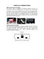
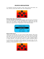
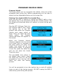
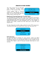
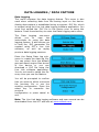
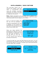
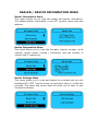
SCT X3 POWER FLASH
USER GUIDE
PART NUMBER 3000 (X3)
IMPORTANT NOTES:
Check all electronic systems and then turn them off
if applicable. This includes fuel pumps, fans, stereo
systems etc. Make sure the ignition key is turned
OFF.
BEFORE ATTEMPTING TO PROGRAM YOUR VEHICLE, YOU
MUST FIRST PLUG THE DEVICE INTO A WINDOWS-BASED PC
OR LAPTOP AND UPDATE THE DEVICE.
Please read the user manual completely and go to the Device Info
menu to confirm your Firmware version and Tune Revision version.
Visit www.sctflash.com to check for updates or newer versions of
the Firmware or Tune revision. It is critical that the update process
is done prior to programming the vehicle.
Plug the device into the OBD-II port and wait for the main menu
screen to appear. The default menu screen is "Program Vehicle". If
you are calling for technical support for a vehicle that is not
supported, you will need to Read Strategy first through the "Vehicle
Info" main menu screen.
The Keypad will allow you to scroll through the different main menu
screens and the Select/Cancel keys will select/save different submenus. Refer to the next page for more information on device
navigation.
NOTE: SCT does not recommend using this device with any other
tuning module or device that modifies the vehicle PCM parameters,
increases
horsepower,
torque,
or
modifies
transmission
characteristics. Before taking your vehicle to a dealer service
department for any type of service or warranty work, you should
first return the vehicle back to the stock configuration.
GENERAL INFORMATION
The X3 Power Flash is available for use on the following vehicles:
All FPV Vehicles, including:
• BA, BF & FG FPV 6cyl Turbo 4L, Automatic & Manual
Transmission
• BA, BF & FG FPV V8 5.4L 4 Valve, Automatic & Manual
Transmission
All BA, BF & FG Falcons, including:
• BA, BF & FG 6cyl 4L, Automatic & Manual Transmission
• BA, BF & FG 6cyl Turbo 4L, Automatic & Manual Transmission
• BA-BF V8 5.4L 3 Valve, Automatic & Manual Transmission
• BA, BF & FG V8 5.4L 4 Valve XR8, Automatic & Manual
Transmission
All Territory Models, including:
• SX-SY Ford Territory 6cyl 4L, Automatic Transmission
All AU Falcons, including:
• AU 6cyl 4L, Automatic & Manual Transmission
• AU V8 5.0L & 5.6L, Automatic & Manual Transmission
All Australian Delivered Ford Trucks, including:
• 5.4L V8 Petrol F250 & F350 Trucks
• 7.3L V8 Powerstroke Diesel F250 & F350 Trucks
American Vehicles
• Complete Range of American Cars & Trucks as per SCT
Database
X3 Power Flash VIN locks to a single vehicle. You cannot use the
device to tune a new or different vehicle, until you have returned
the original vehicle back to stock, which will unlock the device. You
can only change vehicles 5 times before the unit is permanently
locked.
Standard pre-programmed tuning files are designed for vehicles
with minor performance modifications such as; cold air kits, highflow exhaust systems, and other basic modifications. Vehicles that
have aftermarket superchargers or turbochargers will require
custom tuning. Custom tuning products can be purchased only
through authorized CAPA Custom Tuning Dealers. To locate a dealer
near you, Call CAPA on 08 8582 3499.
CABLES & CONNECTIONS
OBD-II Connection & Cable
The OBD-II cable is designed to interface between the SCT X3
Power Flash and the vehicle PCM. The cable uses a proprietary
connection for the vehicle’s OBD-II port, which can be found under
the dash on the driver’s side of the vehicle (see diagram below).
The port may be labelled as a diagnostic port with a cap covering
the pin connector, which you will need to remove. You will use this
cable/port to program the vehicle, datalog from the vehicle PCM and
view parameters in real-time.
USB Connection & Cable
The USB cable is designed to interface between the SCT X3 Power
Flash and a Windows™-based laptop or PC. You will use this cable
to update the SCT SF3 Power Flash with new firmware or
software/pre-programmed files, and/or download datalog files
stored in the device memory.
USB Port
Bottom of SCT X3 Power Flash
DEVICE NAVIGATION
To navigate through the device main menus and sub-menus use
the; arrows, cancel and select keys. See Image Below.
Device Main Menu Navigation
To scroll through the main menu screens, use the arrow up & down
keys. The active menu will be highlighted with a black bar over the
menu text. To select a menu item, press the select key once the
menu you want to enter is highlighted. See Example Below.
Device Menu Keys
There are six main keys on the X3 Power Flash keypad. The arrow
up & down keys are the primary keys you will use to scroll through
the main menu and sub-menu options. The arrow left & right keys
will be used within the sub-menu screens to view multiple options
or other features. The select key enters or selects individual menus
or sub-menus, and selects option choices. The cancel key will deselect or cancel operations in the submenus and also allows you to
go back to the last screen viewed.
PROGRAM VEHICLE MENU
Program Vehicle
This menu allows you to re-program the vehicle, using one of the
preloaded flash tuning files. Before programming you are able to
adjust the User Adjustable Options on the tuning files.
Flashing Your Vehicle With Pre-Loaded Files
Note: Be sure NOT to remove or unplug the OBD-II cable or turn
the ignition key to the off position during the re-flash process. The
file upload and download status will appear on-screen during each
process.
Plug the SCT X3 Power Flash into
the vehicle’s OBD-II port. Leave
the ignition key in the OFF
position and select the Program
Vehicle main menu option to
begin. Once you select the main
menu
option,
the
Program
Vehicle sub-menu will appear on
the screen.
When
the
Program
Vehicle
submenu appears, use the arrow
up & down keys to navigate to
the menu option you want. The
Install Tune option will be the
default menu option. To program
a tune file, press the select key
and you will enter the Install
Tune sub-menu.
The pre-loaded tune option is
the default menu option. Press
the select key and you will be
prompted to turn the key ON,
which will start the tuning
process.
You will be prompted to turn the ignition key on and off multiple
times as part of the tuning process. DO NOT unplug the OBD-II
cable at any point during this process.
USER ADJUSTABLE OPTIONS
Adjusting User Adjustable Options
User Adjustable Options are contained within the pre-loaded tuning
files. You will be prompted to Adjust User Parameters—Yes / No. To
adjust user options, select Yes. The Adjust User Options menu will
appear and you will navigate through the options using the arrow
up, down, left & right keys. To enter the option or select the option,
use the select key. To cancel the option or go back to the previous
screen, press the cancel key.
The user adjustable options allow you to adjust common vehicle
parameters such as; Fuel Octane, Rev Limiters, Speed Limiters,
Axle Ratio and Tire Size Calibrations, Engine Spark, Engine Timing,
Fuel Table and more.
The available user adjustable options for your vehicle will appear in
the on-screen list. Use the arrow up & down keys to scroll through
the options list and use the select key to enter and modify any
option.
Once you have selected each option to change, you will be
prompted to save all adjustments. Once the adjustments have been
saved to file, you will be prompted to continue the upload process.
Many common user adjustable options are listed near
this user manual. If you have any questions regarding
of available options by vehicle or how to adjust any of
please consult our tech department for further technical
the back of
the number
the options,
assistance.
VEHICLE INFO MENU
This menu allows you to read and
clear diagnostic trouble codes
found in the vehicle PCM. If a
“check engine” light or “service
engine soon” light appears on your
dash, you can check and clear the
codes, which resets the PCM.
Reading & Clearing Diagnostic Trouble Codes
To read diagnostic trouble codes, select the Read DTC’s sub-menu.
The device will display a list of trouble codes. Make a note of each
code displayed and consult the guide at the back of this manual for
additional information on each individual code. For more details on
specific DTC codes, consult the SCT web site or the SCT tech
support line.
To clear diagnostic trouble codes, select the clear DTC’s sub-menu.
The device will clear the vehicle PCM, which will reset the PCM.
Read Strategy
To read the Vehicle Strategy for tech support, select the Read
Strategy sub-menu. You will be prompted to turn the ignition key
ON and the device will automatically read the part number for the
vehicle PCM. Make a note of the part number and keep for your
records.
DATA LOGGING / DATA CAPTURE
Data Logging
This menu accesses the data logging feature. This menu is also
used when collecting data from the analog input on the device.
Analog data capture is established using a program .DLF file, which
is created using the Live Link data logging software application. You
must first upload the .DLF file to the device prior to using this
feature. Press the select key to enter the Data Logging main menu.
The Data Logging sub-menu
allows
you
to
view
the
instructions for using the data
logging feature. It also allows you
to load the .DLF parameter file
created using SCT’s Live Link
software, as well as replay
previous data logging sessions.
Enter the Setup Data Log submenu to create the data log file.
You can select from the default
gas and diesel engine files stored
in the device or you can
download a .DLF file using the
Live Link software application.
You do not need to setup the file
every time you use the feature.
You will be prompted to confirm
that you want to either overwrite
the previous file or use the
existing configuration. Press the
select key to overwrite the
previous
configuration or press cancel to
exit.
Note: The Live Link data logging software and user manual can be
downloaded from the SCT web site at www.sctflash.com.
DATA LOGGING / DATA CAPTURE
This sub-menu allows you to
choose from default .DLF files,
which is recommended when
using the standard pre-loaded
tune files. For custom .DLF files,
consult the Live Link user manual
for additional information.
Note: Default parameters are generated from a generic list of
readable PCM parameters and will vary based on model and engine.
Some parameters may not apply to your vehicle.
Once you select the default .DLF
file you will be prompted to
choose the parameters you wish
to datalog. You are limited to 20
parameters per log and you can
only store one data log file on the
device at any given time.
Once you have selected the
parameters to data log, you will
be prompted to confirm and save
the data log configuration. You
can go back to the list by
pressing the arrow left Key, or
you can continue with saving by
pressing the select key.
To start the data log, enter the Start Data Log sub-menu. You will
automatically be prompted to start the vehicle and press the select
key once the vehicle is running. The data log will start automatically
once the select key is pressed.
DEALER / DEVICE INFORMATION MENU
Dealer Information Menu
This menu allows you to view the dealer and device information.
The default dealer information is the SCT product name and web
address.
Device Information Menu
This menu allows you to view the firmware revision number, serial
number, device status (locked / Unlocked), and the number of
unlocks left (5 maximum).
Device Settings Menu
This menu allows you to view and adjust the contrast and turn the
backlight ON / OFF. Use the arrow up and down keys to modify the
contrast. The select and cancel keys will allow you to save or exit
the device settings.
USER ADJUSTMENT OPTION NOTES
Some options, such as Shift Point 1-2, Shift Point 2-3, Shift Point 34, Shift Firmness 1-2, Shift Firm ness 2-3, Shift Firmness 3-4 will
show up as a choice for vehicles that have a manual transmission.
In these cases simply move to the next item without making
adjustments to them As noted, the only supercharger tunes
available are for vehicles originally equipped with a blower from
Ford, such as ‘03-04 Cobra, ‘99 and up Lightning and Harley trucks.
If you later add a supercharger, turbo or nitrous to your vehicle or
add a more ‘wild’ naturally aspirated combination of parts, you will
need to obtain a custom tuned device from a CAPA dealer.
Additionally, the X3 Power Flash should NOT be used on vehicles
that you have installed power adders on because the tuning options,
while very flexible, are not comprehensive enough to support such
changes. You risk serious engine damage if you add such upgrades
to your vehicle and attempt to tune for the combination with the X3
Power Flash. A custom tuned device from an SCT dealer is
necessary in all such cases.
Other Information:
In the event the X3 Power Flash does not successfully flash the
vehicle it will display an error message. If this happens, you must
recover the ECU. Turn the key off and program the vehicle with the
RETURN TO STOCK option. You may then try again.
Caution:
On 1994-1997 vehicles that are flashed, it is necessary to remove
the battery cable after re-flashing to clear the PCM’s adaptive
memory.
IMPORTANT POINTS TO REMEMBER
•
Remove the fuel pump fuse and fan fuse before flashing. Be
sure heater fans, windshield wipers or any other current draw
is minimized during flashing.
•
Do NOT interrupt the flashing process once it has begun, by
disconnecting the cable of battery or pulling the diagnostic
cable.
•
The SF3 Power Flash will not operate if there is a chip or other
aftermarket device in the J3 port. Remove all chips.
•
Never attempt to reflash ‘on the fly’ or with the engine
running as this will damage the SF3 Power Flash and
processor.
•
Running with lower octane fuel then was intended for the tune
in use can result in engine damage.
•
The SF3 Power Flash becomes ‘VIN’ locked to the vehicle once
it is used.
•
On 1994-1997 vehicles that are flashed, it is necessary to
remove the battery cable after re-flashing to clear the PCM’s
adaptive memory.
•
Never operate the motor vehicle and attempt to datalog.
Have someone else drive the car if you need to do this.
•
Obey all traffic laws.
DTC DIAGNOSTIC TROUBLE CODES
Some
P0100
P0109
P0114
P0115
P0120
P0125
P0170
P0171
P0172
P0173
P0174
P0175
P0190
P0195
P0200
P0213
P0214
P0217
P0218
P0219
P0230
P0300
P0320
P0325
P0335
P0340
P0350
P0382
P0410
P0420
P0440
P0480
P0484
P0485
P0500
P0501
P0505
P0506
P0507
P0510
P0550
P0560
P0561
P0562
P0563
P0606
of the More Common DTC Codes
Mass or Volume Air Flow Circuit Malfunction
Intake Air Temperature Circuit Malfunction
Intake Air Temperature Circuit Intermittent
Engine Coolant Temperature Circuit Malfunction
Throttle/Pedal Position Sensor/Switch A Circuit Malfunction
Insufficient Coolant Temperature for Closed Loop Fuel Control
Fuel Trim Malfunction (Bank 1)
System too Lean (Bank 1)
System too Rich (Bank 1)
Fuel Trim Malfunction (Bank 2)
System too Lean (Bank 2)
System too Rich (Bank 2)
Fuel Rail Pressure Sensor Circuit Malfunction
Engine Oil Temperature Sensor Malfunction
Injector Circuit Malfunction
Cold Start Injector 1 Malfunction
Cold Start Injector 2 Malfunction
Engine Overtemp Condition
Transmission Over Temperature Condition
Engine Overspeed Condition
Fuel Pump Primary Circuit Malfunction
Random/Multiple Cylinder Misfire Detected
Ignition/Distributor Engine Speed Input Circuit Malfunction
Knock Sensor 1 Circuit Malfunction (Bank I or Single Sensor)
Crankshaft Position Sensor A Circuit Malfunction
Camshaft Position Sensor Circuit Malfunction
Ignition Coil Primary/Secondary Circuit Malfunction
Exhaust Gas Recirculation Flow Malfunction
Secondary Air Injection System Malfunction
Catalyst System Efficiency Below Threshold (Bank 1)
Evaporative Emission Control System Malfunction
Cooling Fan I Control Circuit Malfunction
Cooling Fan Circuit Over Current
Cooling Fan Power/Ground Circuit Malfunction
Vehicle Speed Sensor Malfunction
Vehicle Speed Sensor Range/Performance
Idle Control System Malfunction
Idle Control System RPM Lower Than Expected
Idle Control System RPM Higher Than Expected
Closed Throttle Position Switch Malfunction
Power Steering Pressure Sensor Circuit Malfunction
System Voltage Malfunction
System Voltage Unstable
System Voltage Low
System Voltage High
PCM Processor Fault
P0700
P0701
P0702
P0705
P0710
P0712
P0713
P0720
P0723
P0730
P0731
P0732
P0733
P0734
P0735
P0736
P0740
P0745
P0750
P0755
P0760
P0765
P1000
Transmission Control System Malfunction
Transmission Control System Range/Performance
Transmission Control System Electrical
Transmission Range Sensor Circuit malfunction (PRNDL Input)
Transmission Fluid Temperature Sensor Circuit Malfunction
Transmission Fluid Temperature Sensor Circuit Low Input
Transmission Fluid Temperature Sensor Circuit High Input
Output Speed Sensor Circuit Malfunction
Output Speed Sensor Intermittent
Incorrect Gear Ratio
Gear I Incorrect ratio
Gear 2 Incorrect ratio
Gear 3 Incorrect ratio
Gear 4 Incorrect ratio
Gear 5 Incorrect ratio
Reverse incorrect gear ratio
Torque Converter Clutch Circuit Malfunction
Pressure Control Solenoid Malfunction
Shift Solenoid A Malfunction
Shift Solenoid B Malfunction
Shift Solenoid C Malfunction
Shift Solenoid D Malfunction
ECM Power Loss
P0101
123
1st digit
P = powertrain
B = Body
C = Chassis
2nd digit
0 = Standard
1 = Manufacturer specific
3rd digit
1 = Emission management
2 = Injector circuit
3 = Ignition
4 = Auxiliary emission
5 = Vehicle speed & idle control
6 = Computer & output circuit
7 = Transmission
FREQUENTLY ASKED QUESTIONS
Q: Do I need to remove my aftermarket performance chip
from the PCM before tuning the vehicle?
A: You must remove all chips from the PCM prior to starting the
tuning process.
Q: Can the vehicle be tuned while the engine is running?
A: NO – This can cause severe damage to the vehicle and PCM.
Q: Can I use a lower octane fuel than what the tuning file is
designed to run?
A: NO – You must use the same octane fuel that the vehicle is
tuned for. Failure to use the proper octane fuel can result in severe
engine damage.
Q: Can I datalog the vehicle while driving?
A: YES, but please make sure you have someone else in the vehicle
with you. Never attempt to datalog the vehicle yourself, while
driving the vehicle.
Q: Is it necessary to disconnect the battery after tuning the
vehicle?
A: On 1994 – 1997 vehicles, you must disconnect the battery cable
for 10 seconds or more to reset the PCM’s adaptive memory.
Q: Does the vehicle need to be running to use or display the
performance monitor?
A: Yes, the vehicle must be running to monitor or datalog data
through the device.
CAPA SUPPORT OPTIONS
Please contact CAPA for support of your X3 Power Flash.
Phone 08 8582 3499
Fax 08 8582 3477
Email [email protected]
CAPA Performance
Lot 10 Kay Ave
Berri, SA
5343