1
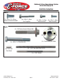
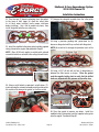
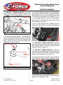
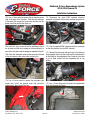
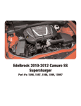
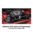
Edelbrock 2010-2014 Camaro SS
Supercharger
Part #’s: 1596, 1597, 1598, 1599, 15997
Edelbrock E-Force Supercharger System
2010-2014 Camaro SS
Installation Instructions
INTRODUCTION
Thank you for purchasing the Edelbrock 6.2L GM Supercharger System for the 2010-14 Chevy Camaro. The Edelbrock
E-Force Supercharger System for the Camaro SS utilizes Eaton’s new Gen VI TVS Supercharger rotors, featuring a four
lobe design with a full 160 deg. of twist for maximum flow, minimum temperature rise, quiet operation, and the reliability
for which Eaton is known. The Edelbrock Supercharger is a complete system that maximizes efficiency and performance
by minimizing air restriction into, and out of, the supercharger. This results in maximum airflow, with minimal temperature
rise and power consumption. The supercharger housing itself is integrated into the intake manifold for a seamless design
with minimal components, eliminating the possibility of vacuum leaks between gasket surfaces. The system also utilizes
a front drive, front inlet configuration giving it the shortest, least restrictive inlet path on the market. The supercharger
is inverted, expelling the air upward. Air pressure then builds in the plenum, before being drawn down through each
of two intercooler cores, oriented horizontally, next to, and below the supercharger outlet. After passing through the
intercooler cores, the air travels through the long 12” individual intake runners, which route underneath the supercharger
housing to the cylinder head ports, in a horizontal, nested configuration. The upper plenum area is enclosed by a top
cover that has been designed to provide an appealing and distinctive under-hood appearance. This configuration allows
for a compact package that can fit under the stock hood and cowl of the Camaro, without sacrificing runner length, or
intercooler area. The E-Force supercharger features a uniquely styled plenum, and includes matching side covers. The
Edelbrock supercharger provides neck snapping performance that is safe to operate on a completely stock engine. It
is 50-state emissions legal, and can be had with an optional 5-year 100,000 mile warranty so that there are no worries
when installing it on a brand new car.
TOOLS REQUIRED
l Jack and Jack Stands
OR Service Lift
l Panel Puller
l Ratchet and Socket Set including: 7mm, 8mm, 10mm
(standard, deep and universal), 12mm (deep), 13mm,
15mm (deep), 18mm, 21mm (deep), 24mm
l Wrenches including: 8mm, 13mm, 16mm, 18mm,
13/16”, 3/4”
l Crescent Wrench
l 12” Ratchet Extension Bar
l 1/2” Breaker Bar
l Flat Blade & Phillips Screwdrivers
l Compressed Air
l Torx-20 Driver
l Allen Wrenches including: 6mm, 8mm
l 3/8” Fuel Line Removal Tool
l Torque Wrench
l Needle Nose Pliers
lPliers
OR Hose Clamp Removal Tool
l Pneumatic or Power Drill
l 1-1/8” or larger Uni-bit
l Impact Wrench
l Red & Blue Loctite or equivalent
l O-ring Lube
l Thread Sealing Compound
lAnti-seize
l Masking Tape
l J-42386-A Flywheel Holding Tool
l Soldering Iron
Edelbrock LLC, 2700 California Street, Torrance, CA 90503
Toll-Free Tech Line: 1-800-416-8628 Office/Sales Line: 310-781-2222
©2014 Edelbrock LLC
Part #1596, 1597, 1598, 1599
Page 1
Brochure #63-1598
Rev. 9/19/14 - QT/mc
Edelbrock E-Force Supercharger System
2010-2014 Camaro SS
Installation Instructions
IMPORTANT WARNINGS
Before beginning the installation, use the enclosed checklist to verify that all
components are present in the box, then inspect each component for damage
that may have occurred in transit. If any parts are missing or damaged, contact
Edelbrock Technical Support (800-416-8628), not your parts distributor.
WARNING: Installation of this supercharger will result in a significant change to the
performance characteristics of your vehicle. It is highly recommended that you take
some time to familiarize yourself with the added power and how it is delivered. This
must be done in a controlled environment. Take extra care on wet and slippery roads
as the rear tires will be more likely to lose traction with the added power. It is never
recommended to turn off your vehicles traction control system.
Proper installation is the responsibility of the installer. Improper installation will void all
manufacture’s standard warranties and may result in poor performance and engine or vehicle
damage.
Due to the complexity of the Edelbrock E-Force Supercharging system, it is recommended that this system only
be installed by a qualified professional with access to a service lift, pneumatic tools, and a strong familiarity with
automotive service procedures. To qualify for the optional supplemental warranty, it is necessary to have this
system installed by a Certified ASE Technician at a licensed business, GM Dealership, or an Authorized Edelbrock
Installer. Failure to do so will void and/or disqualify any and all optional supplemental warranties offered with this
system. Please contact the Edelbrock Technical Support department if you have any questions regarding this
system and/or how your installer of choice will affect any warranty coverage for which your vehicle may qualify.
Please see warranty contract for all details and restrictions.
Any previously installed aftermarket tuning equipment must be removed and the vehicle returned
to an as stock condition before installing the supercharger.
Any equipment that directly modifies the fuel mixture or ignition timing of the engine can cause severe engine
damage if used in conjunction with the Edelbrock E-Force Supercharger System. This includes, but is not limited
to: OBDII programmers, MAF sensors, adapters and any other device that modifies signals to and/or from the
ECU. Aftermarket bolt-on equipment such as underdrive pulleys or air intake kits will also conflict with the
operation of the supercharger and must be removed prior to installation. Use of any of these products with the
E-Force Supercharger could result in severe engine damage.
©2014 Edelbrock LLC
Part #1596, 1597, 1598, 1599
Page 2
Brochure #63-1598
Rev. 9/19/14 - QT/mc
Edelbrock E-Force Supercharger System
2010-2014 Camaro SS
Installation Instructions
IMPORTANT WARNINGS (CONTINUE)
Edelbrock periodically releases improved versions of the calibration file found on the supplied handheld
programmer. It is recommended to check the website, www.edelbrock.com, to ensure you have the
latest version as described in the PCM Flashing Procedure on Page #9.
It is also recommended that you check the Edelbrock Tech Center Website for any updates to this
installation manual. Please refer to the lower right hand corner to verify that you have the latest revision
of this installation manual before beginning the installation.
Tech Center: http://www.edelbrock.com/automotive_new/misc/tech_center/install/index.php
91 octane or higher gasoline is required at all times. If your vehicle
has been filled with anything less, it must be run until almost dry and
refilled with 91 or higher octane gasoline twice prior to installation.
Failure to use the required 91 octane gasoline or higher could
permanently damage your engine. Any failures associated with not
using premium 91 octane gasoline or higher, will be ineligible for
warranty repairs.
Edelbrock Authorized Installer Disclaimer
Authorized installers of Edelbrock products are independent companies over which Edelbrock has no right of control. Edelbrock LLC makes
no claims regarding the abilities, expertise or competency of individual employees of any authorized installer. Each authorized installer is
an independent company and makes its own independent judgments. Edelbrock LLC specifically disclaims any responsibility to any party
including third parties for the actions, or the failure to act, of individuals, agents or a company authorized in the installation of Edelbrock LLC
products.
©2014 Edelbrock LLC
Part #1596, 1597, 1598, 1599
Page 3
Brochure #63-1598
Rev. 9/19/14 - QT/mc
Edelbrock E-Force Supercharger System
2010-2014 Camaro SS
Installation Instructions
INSTALLATION HARDWARE IDENTIFICATION GUIDE
Bag #1
(1x) - M10 x 1.5 x 65mm Socket Head Bolt
(3x) - M8 x 1.25 x 100mm Socket Head Bolt
(1x) - M10 x 1.5 x 75mm Hex Flange Bolt
(2x) - M8 Washer
(3x) - M8 x 1.25 x 20mm
Hex Flange Bolt
Bag #2
(1x) - M6 x 1 x 25mm
Hex Stand-Off
(4x) - M8 x 1.25 x 20mm
Hex Flange Bolt
(2x) - 1/2” Hose Clamp
(1x) - M5 X .8 X 25mm
Hex Stand-Off
(7x) - 3/4” Hose Clamp
(1x) - M8 x 1.25 x 30mm
Hex Flange Bolt
(2x) - Nylon Body Pin
(4x) - M6 x 1 x 10mm
Hex Flange Bolt
(1x) M5 X .8 X10mm
Socket Head Bolt
(1x) - Lower Intercooler Reservoir Bracket
(4x) - M8 x 1.25
Hex Flange Nut
(1x) - Upper Intercooler Reservoir Bracket
©2014 Edelbrock LLC
Part #1596, 1597, 1598, 1599
Page 4
Brochure #63-1598
Rev. 9/19/14 - QT/mc
Edelbrock E-Force Supercharger System
2010-2014 Camaro SS
Installation Instructions
Bag #3
(11x) - M8 x 1.25 x 25mm
Countersunk Socket Head Bolt
(8x) - M6 x 1 x 45mm
Hex Flange Bolt
(4x) - M6 x 1 x 12mm
Socket Head Bolt
(2x) - M6 x 1 x 16mm
Button Head Bolt
Bag #4
(1x) - GM Factory Harmonic Balancer Bolt
Bolt Hole
Drill Hole
(1x) - Crank Pinning Drill Guide
(1x) - M16 x 2 x 120mm Hex Bolt
(1x) - 1/4” x 3/4”
Steel Dowel
Ream Hole
(1x) - 15/64” High Speed Steel Drill Bit
(1x) - .2500” Reamer
©2014 Edelbrock LLC
Part #1596, 1597, 1598, 1599
Page 5
Brochure #63-1598
Rev. 9/19/14 - QT/mc
Edelbrock E-Force Supercharger System
2010-2014 Camaro SS
Installation Instructions
Bag #5
(1x) - Coil Cover
Dipstick Grommet
(4x) - Coil Cover
Bracket Grommet
(4x) - Coil Cover Bracket
(4x) - Coil Cover Retainer Stud
(4x) - Coil Cover Standoff
©2014 Edelbrock LLC
Part #1596, 1597, 1598, 1599
Page 6
Brochure #63-1598
Rev. 9/19/14 - QT/mc
Edelbrock E-Force Supercharger System
2010-2014 Camaro SS
Installation Instructions
HOSE IDENTIFICATION GUIDE
Intercooler Water
Pump to Heat
Exchanger Hose
Heater Core
Hose Assembly
Fuel Rail Inlet
Fuel Rail Crossover
Intercooler
Reservoir to Water
Pump Hose
Manifold to EVAP
Solenoid Hose (18”)
EVAP Solenoid to
EVAP Hard Line
(21”)
Brake Booster to
Manifold Hose
Driver Side PCV Hose (22”)
Passenger Side
PCV Hose (24”)
Intercooler Hose
Assembly
Dual Mode
Exhaust Splitter
Hose
©2014 Edelbrock LLC
Part #1596, 1597, 1598, 1599
Driver Side Manifold to
Intercooler Reservoir Hose
Passenger Side Manifold to
Intercooler Reservoir Hose
Page 7
Brochure #63-1598
Rev. 9/19/14 - QT/mc
Edelbrock E-Force Supercharger System
2010-2014 Camaro SS
Installation Instructions
Supercharger Installation
NOTE: It is very important to perform the PCM flashing
procedure prior to starting this installation. This will
prevent any major installation delays due to non-compatible
calibration files.
In the rare occurrence that you encounter an error message
during the PCM flashing procedure, please refer to Page 28,
titled E-mail Edelbrock Your Stock PCM Calibration.
WARNING: Battery must be sufficiently charged before
starting the PCM flashing procedure.
Only begin the PCM flashing procedure when you are
ready to install the supercharger. Once the PCM is
flashed, DO NOT START the engine until the installation
of the E-Force supercharger is complete.
1. Before starting the flash procedure, check the
Edelbrock website at:
(http://www.edelbrock.com/automotive/mc/
superchargers/support.shtml)
to confirm that you have the latest calibration file. Once
you have found the latest calibration file on the website,
power on the programmer. Press the left arrow and select
the “Device Info” option. Scroll down to “Tune Version”
and compare the tune number to the one on the website.
If they are different, download the new calibration file with
the supplied USB cable.
5. Use the directional pad to highlight the Pre-programmed
Tune option and press the Select button.
6. Read the disclaimer then press Select to continue.
7. Verify that the ignition is in the ‘Key On’ position and
that the engine is not running, then press Select.
8. Use the directional pad to highlight your vehicle and
transmission combination then press Select.
9. Use the directional pad to highlight the Begin Program
option then press Select.
10. Depending on your specific drivetrain configuration,
several separate operations may take place during this
step. Completion of each operation will cause the progress
bar to reset to zero.
11. DO NOT unplug the programmer until prompted.
2. Put the car into ACC mode, but don’t start the vehicle.
12. Turn the vehicle off when prompted to do so by the
handheld programmer.
3. Connect the supplied PCM cable on the handheld
programmer to the OBD-II connector located below the
steering wheel, and to the left of your knee.
13. Read the parting message from programmer then
press Select to continue.
4. Use the directional pad to highlight the Program
Vehicle option and press the Select button.
14. Unplug the programmer cable from the OBD-II port.
This concludes the PCM flashing procedure. DO NOT start
the engine until the supercharger installation is complete.
15.Open trunk and lift trunk liner to access plastic hold
down. Unscrew plastic hold down then remove air
compressor and foam support.
16.Use a 10mm socket to loosen and remove the negative
battery terminal.
©2014 Edelbrock LLC
Part #1596, 1597, 1598, 1599
Page 8
Brochure #63-1598
Rev. 9/19/14 - QT/mc
Edelbrock E-Force Supercharger System
2010-2014 Camaro SS
Installation Instructions
17.Lift the protective cover then use a 10mm socket to
loosen and remove the positive battery terminal.
21. Disconnect the fog lamp electrical connectors and the
fascia wiring harness connector on the passenger side.
22.Use a 10mm socket to remove the two bolts retaining
the bottom of the fascia.
18.Lift and support the front end of the vehicle using a
service lift or jack and appropriately load rated jack stands
then loosen and remove the lug nuts from both front wheels.
Remove the wheels and set them aside.
19.Use a T20 Torx wrench to remove the three bolts on each
side holding the front and the two holding the rear of the
front wheel fender liners. Use a panel puller to remove the
five body pins on each side that retain the inner fender wells
then remove them and set them aside.
23.Use a panel puller to remove the six body pins holding
the top of the fascia then use a 10mm socket to remove the
bolt at each end of the top of the fascia.
24.The front fascia can now be removed by pulling it
forward off the vehicle. Set front fascia aside.
25.Remove the oil fill cap and remove the plastic engine
cover. Reinstall the oil fill cap.
26.Disconnect the Mass Airflow Sensor connector. 20.Reach in through the wheel wells with a 10mm socket
to remove the four bolts at the front of each side of the
fascia then use a 7mm socket to remove the two bolts on
each side of the front fascia.
©2014 Edelbrock LLC
Part #1596, 1597, 1598, 1599
Page 9
Brochure #63-1598
Rev. 9/19/14 - QT/mc
Edelbrock E-Force Supercharger System
2010-2014 Camaro SS
Installation Instructions
27.Use a flat head screwdriver to loosen the worm clamp
holding the inlet tube to the air box lid then remove the air
box lid by pushing the lock tabs back.
32. Push down the white tab on the front EVAP hose fittings
and disconnect them from the manifold and the EVAP
solenoid. 28.Disconnect the passenger side PCV tube from the valve
cover then use a flat head screwdriver to loosen the worm
clamp retaining the air intake tube to the throttle body.
Remove the air intake tube and PCV hose.
29.Use a 15mm socket and a breaker bar to loosen the
tensioner and remove the serpentine belt. 33.Disconnect the Manifold Air Pressure sensor and EVAP
solenoid electrical connectors.
NOTE: 2013 model years disregard Step 34 and proceed to
Step 35. 2014 model years proceed with Step 34.
34.Disconnect the PCV tube from the engine valley cover.
30. Disconnect the throttle body control connector on the
passenger side of the throttle body.
NOTE: Step 35 only pertains to 2013 model years. Please
disregard otherwise.
31. Use a 10mm socket to remove the four bolts retaining
the throttle body and set it aside.
©2014 Edelbrock LLC
Part #1596, 1597, 1598, 1599
35.Remove the driver side PCV on the rear of the diver side
valve cover and on the passenger side of the throttle body.
Page 10
Brochure #63-1598
Rev. 9/19/14 - QT/mc
Edelbrock E-Force Supercharger System
2010-2014 Camaro SS
Installation Instructions
36.Use a 3/8” Fuel Line Removal Tool to disconnect the
fuel line from the fuel rails and from the passenger side
fender fitting. Use a shop rag to absorb any excess fuel. 41. Use a 10mm socket to remove the nut on the driver
side and remove the plastic manifold webbing.
42. Use an 8mm socket to remove the manifold bolt on the
driver side retaining the fuel rail bracket. 37. Use a 10mm socket to remove the nut holding down
the fuel line clamp then remove the fuel line and clamp.
38. Disconnect the two ignition harness connectors, the
eight spark plug wires from the ignition coils and the eight
fuel injector electrical connectors.
39.Use a 10mm deep socket to remove the five studs
retaining each of the ignition coil brackets to the valve
covers. Lift and remove the coil brackets as an assembly.
43.Use a 10mm deep socket to remove the four fuel rail
studs. Remove the fuel rail bracket then remove the rails
by lifting the injectors straight up out of their provisions then
work the rails forward and set them aside.
44.Use an 8mm socket to remove the nine remaining
manifold bolts. Note that the rearmost passenger side bolt
will come out with the manifold and that it is necessary to
rotate the manifold towards the passenger side to remove
the rearmost driver side bolt and the bracket it retains. 40. Disconnect the EVAP hose from the EVAP Solenoid and
the EVAP hard line located on the passenger side.
©2014 Edelbrock LLC
Part #1596, 1597, 1598, 1599
Page 11
Brochure #63-1598
Rev. 9/19/14 - QT/mc
Edelbrock E-Force Supercharger System
2010-2014 Camaro SS
Installation Instructions
45.Use a pair of hose clamp pliers to loosen the clamp
retaining the vacuum hose to the brake booster fitting and
disconnect the hose. It will be removed with the manifold.
NOTE: Steps 50-60 outlines the procedure for disabling
the Active Fuel Management system found on Camaros
equipped with automatic transmissions. Manual vehicles
disregard Steps 50-60 and proceed to Step 61.
WARNING: The supplied valley plate must be used on
all installs. FAILURE TO DO SO WILL RESULT IN ENGINE
DAMAGE.
NOTE: Step 46 only applies to vehicles equipped with dual
mode exhaust systems. Disregard and proceed to Step 47
otherwise.
46.Disconnect the Dual Mode Exhaust Hose on the manifold
from the hard line. TIP: Valley plates with AFM systems will have solenoids
attached to the backside of the valley plate as pictured
below. Valley plates without AFM systems will not.
There are two (2) variants of the AFM valley trays:
- Use Steps 50-55 if your solenoid assembly is secured
to the valley plate with Torx bolts.
- Use Steps 56-60 if your solenoid assembly is secured
to the valley plate with rivets.
50.Use a T-20 Torx driver to remove the four (4) bolts
retaining the plastic solenoid bracket, then pry open the clip
at the rear of the plate to remove the bracket.
47.Lift the rear of the manifold and pull it forward to
remove. Remove the o-ring seals from the manifold flanges
and set them aside as they will be reused.
48.Use a clean shop rag to wipe down the intake flange of
both cylinder heads then put a small strip of masking tape
over each port to prevent debris from entering.
51.Rotate each solenoid 90° clockwise and remove.
49.Unplug the oil pressure sensor connector. Use a
crescent wrench to remove the oil pressure sensor from the
engine valley plate.
52.Use a T-30 Torx driver to remove the twenty (20) bolts
holding the steel sandwich in place and remove.
53.Carefully remove the plastic and rubber gasket from
the valley plate. Do not discard or damage the seal as it
will be reused.
©2014 Edelbrock LLC
Part #1596, 1597, 1598, 1599
Page 12
Brochure #63-1598
Rev. 9/19/14 - QT/mc
Edelbrock E-Force Supercharger System
2010-2014 Camaro SS
Installation Instructions
54.Trim the two (2) bosses projecting from the gasket
to the base of their tapers to allow the valley plate
to sit flush when installed (verify proper clearance
before installing). Use a file to remove any burrs, then
install the gasket onto the new valley tray.
55.Install the modified valley plate gasket and the supplied
valley plate onto the engine and proceed to Step 65.
NOTE: Steps 56-60 only applies to vehicles with solenoid
assemblies which are secured to the valley plate with rivets.
Disregard otherwise.
57.Remove the solenoid assembly from the valley plate
and carefully remove the gasket.
58.Using a precision grinding tool, grind down six (6)
bosses on the gasket until they are flush with the gasket.
NOTE: Be careful not to damage the perimeter seals of the
gasket.
Perimeter Seals
59.Using a 5/32” dill bit, drill out four (4) bleed holes in
between the lifter bosses as shown. Place the gasket
onto the supplied valley plate to verify that the drilled
holes are aligned with the grooves on the valley tray. 56.Using a cutoff wheel or equivalent, cutoff eleven (11)
rivets securing the solenoid assembly onto the valley plate.
Be careful not to damage the gasket as it will be reused.
Lifter Bosses
Groove On Valley Tray
60.Clean the gasket to remove any debris. Install the
modified valley plate gasket and the supplied valley plate
onto the engine. Proceed to Step 65.
©2014 Edelbrock LLC
Part #1596, 1597, 1598, 1599
Page 13
Brochure #63-1598
Rev. 9/19/14 - QT/mc
Edelbrock E-Force Supercharger System
2010-2014 Camaro SS
Installation Instructions
NOTE: Steps 61-64 are for Manual Transmission vehicles.
Disregard otherwise and proceed to Step 65.
67.Use a 15mm socket to remove the two bolts retaining
the belt tensioner.
WARNING: The supplied valley plate must be used.
FAILURE TO DO SO WILL RESULT IN ENGINE DAMAGE.
61.Using a 13mm socket, remove the (11) eleven bolts
securing the valley plate, then remove the valley plate. The
metal and rubber gasket beneath the valley plate will be
reused and should be left in place.
62.Use a flathead screwdriver to remove (8) eight o-ring
seals from the underside of the factory valley plate.
63.Inspect each o-ring seal for damage and replace any
that have been compromised. Install the o-ring seals onto
the supplied valley plate.
64.Carefully install the new valley plate making sure not to
dislodge the o-ring seals. NOTE: Steps 68-71 will demonstrate how to install the
Edelbrock heater hoses included with this kit. This
procedure is optional on 2013-14 model years as the factory
heater hoses are adequate.
68.Place a drain pan below the radiator petcock on the
driver side. Remove the radiator cap then loosen the
petcock to drain the engine coolant.
69.Disconnect the two heater hoses from the firewall using
a shop rag to absorb any excess coolant.
65.Apply anti-seize to the underside of the heads of the
eleven countersunk bolts from Bag #3. Using a 5mm Allen
tool and the counter sunk bolts, secure the valley plate to
the engine. Torque to 18 ft-lbs from the center out.
70.Disconnect the two heater hoses from the water pump
using a shop rag to absorb any excess coolant.
66. Apply thread sealant to the threads of the oil pressure
sensor then use a crescent wrench to install the sensor in
the new valley plate. Reconnect the oil pressure sensor
electrical connector.
©2014 Edelbrock LLC
Part #1596, 1597, 1598, 1599
Page 14
Brochure #63-1598
Rev. 9/19/14 - QT/mc
Edelbrock E-Force Supercharger System
2010-2014 Camaro SS
Installation Instructions
71.Install the supplied Heater Core Hose Assembly to the
firewall fittings using the supplied hose clamps. Route the
lines between the engine oil dipstick and the fuse box to the
fittings on the water pump and secure them with the
supplied hose clamps. Note that the hose closer to the
passenger side of the firewall will be routed to the fitting
closer to the front of the vehicle and vice versa.
74.Apply blue Loctite, or equivalent, to the threads of the
M8 x 100mm bolts supplied in Bag #1 then use a 6mm
Allen tool to install the idler bracket onto the water pump.
75.Use a 15mm socket to remove the nut retaining the
ground strap on the passenger side cylinder head then use
a 15mm deep socket to remove the ground strap stud. 72.Apply Blue Loctite, or equivalent, to the threads of the
M8 x 20mm bolt supplied in Bag #1 then use a 12mm
socket and washer to install the smaller supplied idler pulley
onto the supplied idler bracket.
76.Apply blue Loctite, or equivalent, to the threads of the
stock tensioner bolts then use a 15mm socket to install the
supplied tensioner bracket to the water pump. 73.Use a 10mm socket to remove the three water pump
bolts indicated.
77.Apply blue Loctite, or equivalent, to the threads of the
M10 x 65mm bolt supplied in Bag #1 then use an 8mm
allen to install it in the countersunk bolt hole of the tensioner
bracket.
©2014 Edelbrock LLC
Part #1596, 1597, 1598, 1599
Page 15
Brochure #63-1598
Rev. 9/19/14 - QT/mc
Edelbrock E-Force Supercharger System
2010-2014 Camaro SS
Installation Instructions
78.Apply blue Loctite, or equivalent, to the threads of an
M8 x 20mm bolt supplied in Bag #1 then use the supplied
washer and a 12mm socket to install the supplied idler
pulley onto the tensioner bracket.
82.Use a 13mm socket (10mm on 2013-14 model years)
to remove the two bolts holding the fan assembly to the
top of the radiator then disconnect the electrical connector
on the passenger side of the fan assembly and remove the
radiator fans.
83.Disconnect the oil level sensor electrical connector from
the passenger side of the oil pan.
79.Apply blue Loctite, or equivalent, to the threads of the
M10 x 75mm bolt supplied in Bag #1 then use a 15mm
socket to install the supplied tensioner onto the tensioner
bracket. 80.Use a 12mm socket and an M8 x 20mm bolt supplied
in Bag #1 to secure the ground strap to the back side of the
tensioner bracket.
NOTE: If not already done so, it’s recommended to drain the
coolant by removing the petcock to avoid coolant spillage.
81.Use pliers to loosen the hose clamps and disconnect
the two small upper radiator hoses. Use caution when
removing and reinstalling hoses onto plastic fittings. 84.Use a 10mm socket to remove the starter support
bracket bolt.
85.Use a 13mm socket to remove the two starter bolts.
86.Use an 8mm wrench to remove the three bolts retaining
the starter heat shield.
87.Disconnect electrical connector at top of starter.
88.Use a 13mm socket to remove the nuts retaining power
wires to the starter.
89.Remove and set aside the starter and bracket.
90.Install GM Flywheel Holding Tool #J-42386-A to prevent
the crank from rotating while loosening the balancer bolt
and torque the bolts holding it to 37 ft/lbs.
©2014 Edelbrock LLC
Part #1596, 1597, 1598, 1599
Page 16
Brochure #63-1598
Rev. 9/19/14 - QT/mc
Edelbrock E-Force Supercharger System
2010-2014 Camaro SS
Installation Instructions
91.Use a breaker bar and a 24mm socket to loosen and
remove the crank bolt. A long pipe slid over the breaker bar
can be helpful for increasing leverage.
102.Reconnect the starter solenoid electrical connector.
103.Use an 8mm wrench to reinstall the three bolts that
hold the starter heat shield in place.
104.Use a 13mm socket to install the two starter bolts.
105.Use a 10mm socket to reinstall the starter support
bracket bolt.
92.Install the drill guide and the M16 x 120mm bolt supplied
in Bag #4 onto the end of the crankshaft.
93.Measure 1.7” from the tip of the 15/64” drill bit supplied
in Bag #4 and mark the position with a piece of masking
tape then drill into the crank through the hole in the guide
that has a bushing in it until the tape mark reaches the drill
guide.
106.Lower the fan assembly back into place, reconnect
the passenger side electrical connector then use a 13mm
socket to reinstall the stock fan assembly bolt on the driver
side only, the passenger side will be installed later.
107.Use a panel puller to remove the two body pins from
the top of the lower radiator shroud. 94.Loosen the bolt holding the drill guide and rotate it until
the second hole lines up with the hole drilled in the crank.
Use the back side of the ream tool to verify the guide is
correctly aligned.
95.Tighten the guide bolt then use compressed air to clean
out any metal flakes in the drill hole.
96.Insert the supplied ream tool through the hole and ream
the full depth of the hole.
97.Use compressed air to clean out any metal flakes then
loosen the bolt and remove the drill guide.
98.Apply red Loctite retaining compound to the supplied
crank pin and tap it into the reamed hole until it is flush with
the crank snout.
NOTE: Convertible models are equipped with a brace that
connects the frame extensions, this brace will need to
be removed and replaced with the Edelbrock Convertible
Brace (Part #15956, Sold Separately) as it interferes with
the installation of the Edelbrock heat exchanger.
108.Install the supplied heat exchanger behind the bumper
so that the lower bracket holes line up with those in the
radiator shroud.
99.Install the crank bolt supplied in Bag #4 and torque it to
37 ft-lbs then rotate it an additional 140°.
100.Remove GM Flywheel Holding Tool #J-42386-A.
101.Lift the starter support bracket and starter into place
then use a 13mm wrench to reinstall the power wire onto
the starter.
©2014 Edelbrock LLC
Part #1596, 1597, 1598, 1599
Page 17
Brochure #63-1598
Rev. 9/19/14 - QT/mc
Edelbrock E-Force Supercharger System
2010-2014 Camaro SS
Installation Instructions
109.Secure the top of the heat exchanger with the two M8
x 20mm bolts supplied in Bag #2 and tighten them with a
12mm socket.
110.Install the M8 nuts and M8 x 20mm bolts supplied in
Bag #2 into the holes in the lower heat exchanger brackets
then use a 12mm wrench and socket to tighten them.
114.Use a Unibit to drill a 1-1/8” hole in the lower radiator
shroud to allow the hose to slide onto the water pump outlet
fitting. Please note that 2014 Model Years will have a
different hole location just left of the LTR. 2010-13 Model Year
111.Install the intercooler water pump bracket on the
studs located on the back of the passenger side of the
bumper. Secure it in place with the M8 nuts supplied in
Bag #2 and tighten them with a 12mm wrench.
2014 Model Year
112.Install the water pump to heat exchanger hose on the
passenger side inlet fitting of the heat exchanger and clock
it until it contacts the lower radiator shroud. Secure the
fitting with a 3/4” hose clamp supplied in Bag #2.
113.Slide the strap over the body of the water pump and
install it in the water pump bracket. Rotate the water pump
and slide it in and out until it roughly lines up with the
position of the hose on the other side of the lower radiator
shroud.
©2014 Edelbrock LLC
Part #1596, 1597, 1598, 1599
115.Use the supplied bolt and a 13mm socket to secure
the water pump by tightening the strap to the bracket. 116.Slide the hose onto the water pump outlet and secure
it with a 3/4” hose clamp supplied in Bag #2.
117.Install the Intercooler Hose Assembly by sliding it
down between the radiator fan assembly and the engine.
Note that the short hose section will go around the radiator
to the outlet of the heat exchanger.
Page 18
Brochure #63-1598
Rev. 9/19/14 - QT/mc
Edelbrock E-Force Supercharger System
2010-2014 Camaro SS
Installation Instructions
118.Use a Unibit to drill a 1-1/8” hole in the radiator
shroud on the driver side directly across from the heat
exchanger outlet.
2012-’14
Figure - 2b
119.Slide the short section of the Intercooler Hose
Assembly through the hole and onto the heat exchanger
outlet. Secure it with a 3/4” hose clamp supplied in Bag
#2.
121. FOR 2010-‘11 MODEL YEARS ONLY Use a 10mm
socket to remove the upper-outside bolt from the backpassenger side of the radiator fan; retain the bolt as it will
be re-used.
120.Mount the brackets, supplied in Bag #2, to the
intercooler reservoir with the M6 x 10mm bolts located in
Bag #2. Refer to figures 2a & 2b for the specific orientation
of the lower bracket for each model year.
122. FOR 2012-‘14 MODEL YEARS ONLY Use a 13mm
wrench to install the standoff stud supplied in Bag #2 in
place of the bolt which was just removed. See Figure 3a.
2010-’11
Figure - 3a
Figure - 1
2010-’11
Figure - 2a
©2014 Edelbrock LLC
Part #1596, 1597, 1598, 1599
Page 19
Brochure #63-1598
Rev. 9/19/14 - QT/mc
Edelbrock E-Force Supercharger System
2010-2014 Camaro SS
Installation Instructions
123. FOR 2012 - ‘14 MODEL YEARS ONLY Use a 10mm
wrench to install the standoff, supplied in Bag #2, to the
stud located on the back of the radiator fan. See Figure 3b
2012-’14
125.Lower the intercooler reservoir and its attached hose
down into the passenger side of the engine bay so that the
lower bracket will line up with the mounting hole (Refer
to the Figure that corresponds to your model year;“3a” or
“3b”), the upper bracket will line up with the passenger
side radiator fan assembly bolt and the hose will mate up
to the intercooler water pump.
126.Use a 13mm (10mm for 2012-’14 Models) socket to
reinstall the stock radiator fan assembly bolt through the
upper reservoir bracket. Figure - 3b
124.Install the intercooler reservoir - water pump hose
onto the outlet of the intercooler reservoir so that the other
end will extend down to the inlet of the intercooler water
pump. Secure the hose to the reservoir fitting with a
supplied hose clamp. See Figure 4.
To passenger side manifold
To driver side manifold
127. FOR 2010-‘11 MODEL YEARS ONLY Secure the
lower intercooler reservoir bracket to the back of the fan by
using a 10mm socket to re-install the stock bolt onto the
standoff stud.(Refer to Figure “3a”).
128. FOR 2012-’14 MODEL YEARS ONLY Secure the
lower intercooler reservoir bracket to the back of the fan by
using a 4mm allen to install the M5 X 10mm bolt, supplied
in bag 2, onto the spacer.(Refer to Figure“3b”).
129.Secure the intercooler reservoir to water pump hose
to the inlet of the water pump with a supplied hose clamp.
To water pump
Figure 4
130.Install the factory o-ring intake seals into the machined
grooves of the supercharger flanges.
©2014 Edelbrock LLC
Part #1596, 1597, 1598, 1599
Page 20
Brochure #63-1598
Rev. 9/19/14 - QT/mc
Edelbrock E-Force Supercharger System
2010-2014 Camaro SS
Installation Instructions
131.Two of the stock manifold bolt hole provisions in
the cylinder heads break into the crankcase and are not
used with this supercharger. These must be plugged by
installing two button head bolts supplied in Bag #3 in
the front passenger side and rear driver side bolt holes
to ensure a good seal.
132.Remove the tape covering the intake ports.
133.Connect the TMAP harness to the TMAP sensor at the
rear of the supercharger manifold. Bundle the harness up
and wrap over the top of the manifold to avoid damage
during installation of the supercharger.
NOTE: Automatic Vehicles: 2010-’12 use belt #4061065
(106.5”). 2013-’14 use belt #4060102 (102”).
Manual Vehicles: 2010-’12 use belt #4061065 (105.5”).
2013-’14 use belt #4060102 (101.5”).
135.Route the supplied drive belt according to the diagram
below, except for the idler pulley adjacent to the tensioner.
Use a 15mm wrench to push the tensioner in enough for
the belt to slip on the idler pulley then inspect the belt
installation to make sure it is properly aligned.
Vehicles w/ Power Steering Pump
S/C
P/S
PUMP
TENS
WATER
PUMP
IDLER
IDLER
ALT
IDLER
CRANK
SHAFT
Vehicles w/ Electric Power Steering
S/C
134.With the assistance of one or more people, lift the
supercharger assembly onto the engine. Use a 10mm
universal socket to install the M6 x 45mm intake manifold
bolts supplied in Bag #3 and torque them to 89 in/lbs in the
sequence shown below.
TENS
IDLER
WATER
PUMP
IDLER
IDLER
IDLER
IDLER
CRANK
SHAFT
ALT
136.Apply o-ring lube to the seals of each of the fuel rail
fittings. Use a 13/16” wrench to install the plug in the rear
of the driver side rail and a 3/4” wrench to install the
crossover fittings in both rails as well as the inlet fitting at
the rear of the passenger side rail. Clock the inlet fitting to
the rounded side of the fuel rail.
©2014 Edelbrock LLC
Part #1596, 1597, 1598, 1599
Page 21
Brochure #63-1598
Rev. 9/19/14 - QT/mc
Edelbrock E-Force Supercharger System
2010-2014 Camaro SS
Installation Instructions
137.Apply o-ring lube to the upper seals of the supplied
fuel injectors and install them into the supplied fuel rails
so that the electrical connectors are oriented towards the
rounded side of the rails.
138.Lower the passenger fuel rail assembly onto the
manifold lining up the injectors with their provisions on the
manifold. Gently, push down on the rails until the injectors
are fully seated. Secure fuel rail using a 5mm Hex tool and
two (2) M6 x 12mm bolts from Bag #3.
141.Connect the supplied Fuel Rail Crossover line with the
90° fittings to the passenger side fuel rail. Route the
crossover line below the hub snout and air inlet of the
supercharger and over to the front of the driver side rail.
Clip the Fuel Rail Crossover line onto the driver side fuel rail
fitting. 139.Install the supplied Fuel Rail Inlet between the EVAP
fitting and fuel rail fitting on the passenger side. DO NOT
install this fuel input line onto the smaller 8mm barb meant
for the EVAP.
142.Reattach the fuel injector electrical connectors.
143.Install the 90° end of the Manifold to EVAP Solenoid
Hose to the fitting directly below the supercharger snout.
Route the other end of the hose under the EVAP solenoid
and connect it to the grey barb on the EVAP solenoid.
140.Install the supplied Brake Booster to Manifold Hose
onto the brake booster fitting and secure it with the 3/4”
hose clamp supplied in Bag #2. Then connect the other
end of the brake booster hose to the fitting on the driver
side of the supercharger air inlet and secure it with another
3/4” hose clamp supplied in Bag #2. 144.Connect the 90° end of the EVAP Solenoid to EVAP
Hard Line Hose to the black barb on the EVAP Solenoid (side
with connector). Route the hose back over the passenger
side coils and connect to the EVAP hard line. DO NOT
confuse the 10mm fuel output line with the 8mm EVAP line.
145.Use a 10mm wrench to remove the valve cover ball
stud from the driver side valve cover (if applicable).
146.Use a pair of pliers to remove the vacuum cap from
the rear of the driver side valve cover (if applicable).
©2014 Edelbrock LLC
Part #1596, 1597, 1598, 1599
Page 22
Brochure #63-1598
Rev. 9/19/14 - QT/mc
Edelbrock E-Force Supercharger System
2010-2014 Camaro SS
Installation Instructions
NOTE: Step 147-148 are for vehicles equipped with Dual
Mode Exhaust Systems. Disregard otherwise.
NOTE: Step 149 is for vehicles without Dual Mode Exhaust
Systems. Disregard otherwise.
Vehicles equipped with Dual Mode Exhaust Systems will
have to “T” into the driver side PCV hose using the supplied
splitter hose.
149.Connect the Driver Side PCV Hose to the straight
fitting on the driver side air inlet. Route the PCV to the
vacuum fitting at the rear of the driver side valve cover and
clip it into place.
147.Using a hose cutter, cut the driver side PCV hose
approximately 5 inches from the 90° fitting. Approximately 5 inches
148.Install the supplied splitter hose onto the modified
driver side PCV hose. Install the 90° fitting on the PCV hose
to the barb on the rear of the driver side valve cover. Install
the straight fitting on the PCV hose to the front barb of the
manifold nose. Install the splitter hose to the Dual Mode
Exhaust Hard Line. Proceed to Step 150.
150.Use a small flat blade screwdriver to remove the wire
loom covers from the back of the ignition coil brackets.
Dual Mode Exhaust Hard Line
151.Use a 10mm socket to reinstall the coil brackets
using the five stock studs on each side then reconnect the
ignition coil harness electrical connectors and the spark
plug wires to the ignition coils.
Dual Mode Exhaust
Hard Line
152.Use a 10mm socket to remove the two bolts holding
the ignition coils for cylinders #2, #3, #6 & #7.
153.Install the supplied rubber grommets into the supplied
coil cover brackets. Instal the coil cover brackets on top of
the ignition coils then reinstall the ignition coil bolts. ©2014 Edelbrock LLC
Part #1596, 1597, 1598, 1599
Page 23
Brochure #63-1598
Rev. 9/19/14 - QT/mc
Edelbrock E-Force Supercharger System
2010-2014 Camaro SS
Installation Instructions
154.Install the Passenger Side Manifold to Intercooler
Reservoir Hose between the manifold and reservoir then
secure the reservoir fitting with a hose clamp supplied in
Bag #2. Refer to figure 4 on page 20.
161.Connect the throttle body connector extension harness
to the stock throttle body connector and route the extension
harness so that it will clear the serpentine belt and connect
it to the throttle body connector on the throttle body.
155.Install Driver Side Manifold to Intercooler Reservoir
Hose between the manifold and reservoir then secure the
reservoir fitting with a hose clamp supplied in Bag #2.
Refer to figure 4 on page 20.
156.Connect the Intercooler Hose Assembly to the rear
facing driver side fitting and the side facing passenger side
fitting. Push each hose end on until it clicks into place.
157.Use a 16mm wrench to install the coil cover standoffs
on the valve covers.
162.Use a T20 Torx bit to remove the MAF sensor from
the stock air box cover and install it in the supplied air box
cover. The arrow on the side of the sensor should point
back towards the supercharger.
163.Replace the stock air filter with the one supplied.
158.Install the factory throttle body O-ring into the
machined groove on the supercharger air inlet.
164.Slide the supplied worm clamps over each end of the
supplied silicone tube then slide the tube onto the outlet of
the supplied air box cover. Install the cover by sliding the
tabs into the holes on the driver side of the air box while
sliding the silicone tube onto the throttle body. Push down
on the cover until the tabs snap into place. 159.Use a 10mm socket, the four stock bolts and the stock
O-ring gasket to install the throttle body on the supercharger
air inlet flange.
165.Use a flathead screwdriver to tighten the worm
clamps on each end of the silicone tube.
160.Route the TMAP wiring harness below the supercharger
hub snout towards the driver side using care to secure it
well away from the serpentine belt.
©2014 Edelbrock LLC
Part #1596, 1597, 1598, 1599
166.Connect the stock MAP & MAF sensor wiring harness
connectors into the supplied TMAP wiring harness then
connect the TMAP harness to the MAF sensor.
Page 24
Brochure #63-1598
Rev. 9/19/14 - QT/mc
Edelbrock E-Force Supercharger System
2010-2014 Camaro SS
Installation Instructions
167.Use a 13mm socket to remove the nut from the power
stud at the front of the fuse box. Slide the ring connector
at the end of the orange wire on the relay harness over the
power stud then reinstall the stock nut. 171.Disconnect the stock EVAP solenoid electrical
connector and plug it into the color matched receptacle on
the relay harness.
168.Install the relay on the tab on the passenger side of
the fuse box and the fuse housing on the brace directly in
front of the fuse box using the body pins supplied in Bag #2.
172.Clip the supplied EVAP solenoid electrical connector
on the relay harness into the EVAP solenoid.
169.Route the intercooler water pump connector attached
to the relay down to the water pump and plug it in.
170.Use a 10mm socket to remove the passenger side
fender bolt, install the ground strap ring connector
underneath it, then reinstall the bolt.
©2014 Edelbrock LLC
Part #1596, 1597, 1598, 1599
173.Connect the passenger side pcv hose to the fitting on
the passenger side valve cover and carefully route the hose
to the fitting on the underside of the silicone air inlet tube
so as to avoid contact with the serpentine belt or any
pulleys.
174.Use a 10mm deep socket to install the supplied ball
studs into the new coil covers.
Page 25
Brochure #63-1598
Rev. 9/19/14 - QT/mc
Edelbrock E-Force Supercharger System
2010-2014 Camaro SS
Installation Instructions
175.Install the grommet supplied in Bag #6 in the hole on
the passenger side coil cover.
176.Slide the front fascia back into place and secure it by
reinstalling the stock fasteners, reversing the disassembly
process.
187.Lubricate the grommet on the passenger side coil
cover then install it by sliding the grommet down and
around the dipstick tube and pressing the ball studs into the
bracket grommets. 177.Reconnect the fog light electrical connectors and the
fascia wiring harness connector on the passenger side.
178.Use a 10mm socket to reconnect the positive battery
terminal.
179.Use a 10mm socket to reconnect the negative battery
terminal.
180.Remove intercooler reservoir cap and fill intercooler
system with a 50/50 blend of water and coolant.
181.Reconnect petcock and fill the engine coolant system
with a 50/50 blend of water and coolant (if applicable).
182.Reinstall and secure the front inner fender wells with
the stock fasteners.
183.Reinstall the front wheels and snug the lug nuts.
Lower the vehicle to the ground then torque the lug nuts in
a crossing pattern to 100 ft/lbs.
188.Return the dipstick to the dipstick tube.
189.Install the driver side coil cover by sliding it into place
and pressing the ball studs into bracket grommets.
ongratulations on the installation of your new Edelbrock
C
E-Force Supercharger System. If you have any questions,
please call our Technical Support hotline and one of our
technicians will be happy to assist you.
184.Reconnect the battery terminal if not already done so.
185.Turn the ignition to the ON position but DO NOT start
the vehicle. Closely inspecting the engine bay for any fuel
or coolant leaks. Repair any leaks before operating
vehicle! If no leaks are found, the engine can start.
186.Remove the engine oil dipstick.
©2014 Edelbrock LLC
Part #1596, 1597, 1598, 1599
Page 26
Brochure #63-1598
Rev. 9/19/14 - QT/mc
Edelbrock E-Force Supercharger System
2010-2014 Camaro SS
Installation Instructions
E-mail Edelbrock Your Stock Vehicle Calibration
In the rare occurrence that you encounter an error message that reads “Calibration not supported” during
the PCM flashing procedure on page 8, you will need to e-mail your stock vehicle calibration to Calibration@
edelbrock.com. Otherwise, disregard this step.
• Begin by downloading the SCT device updater software to your computer; it can be downloaded from: http://www.
sctflash.com/software/SCTDeviceUpdater.exe • Put the car into ACC mode but do not start it. • Connect the supplied PCM cable from the tuner to the OBD-II connector. • Select PROGRAM VEHICLE, arrow over to UPLOAD STOCK, press SELECT and follow the prompts on the
screen. • If the upload fails, you will be asked to AUTO DETECT, press SELECT and follow the prompts on the screen. If the auto
detect fail, then please contact Edelbrock Tech support @ 800-416-8628
• Once the stock calibration has loaded, disconnect the programmer from the OBD-II connector and connect it to your PC
using the supplied USB cable. • Open the SCT software and select the button on the lower left hand side that reads GET STOCK FILE FROM DEVICE.
Follow the instructions on the screen. • Once the download is complete e-mail your file to [email protected] or call 1-800-416-8628 and our tech
support staff will assist you in e-mailing the file. NOTE: The subject line of your e-mail should be “file update needed”,
The file will automatically be labeled using your VIN # followed by “.sul “ (XXXXXXXXXXXXX.sul)
• Once we have this file we can update the tune to work with your application, then we will e- mail you the custom tune
which you may use until the release version is available. (This process can usually be completed within 1 to 2 business
days)
• Download the new tune to the programmer using the directions received with the custom tune.
• Re-try the test flash procedure using the custom tune
©2014 Edelbrock LLC
Part #1596, 1597, 1598, 1599
Page 27
Brochure #63-1598
Rev. 9/19/14 - QT/mc