1
•
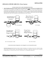
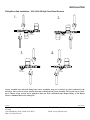
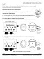
Select Fuel-Tron Mounting Location, (If Used). The instruments’ face is waterproof and a gasket is provided to seal its bezel to
the control panel. Choose a shaded location since direct sunlight may cause the LCD display to temporarily turn dark. This does
not damage the LCD, but makes it impossible to read until cooling down. Make a cutout in the instrument panel for the FuelTron. Instrument. It has a 2” diameter and its maximum depth is approximately 1-7/8” minus the thickness of the console panel.
Mounting bracket studs extend down another ½”.
•
Pre-Startup & Installation Check. Always Prime the FloScan Fuel Monitoring System. This is an important step in preventing
your engine from becoming air bound. If you have an electric priming or boost pump, circulate fuel for 10 minutes while
checking for leaks. If the fuel system does not have an electric priming pump, use the engines manual pump. Before starting, open
or crack the lift pumps’ outlet fitting slightly. Continue pumping all air is purged and fuel flow from the lift pumps outlet. Before
start-up verify that all fuel system fittings are tight.
•
System Start-Up. Start and run your engines. Survey the installation for leaks and other problems. If the system is not operating
properly refer to the Troubleshooting Instructions and correct any deficiencies. When the engine reaches operating temperature
increase engine speed to about 1500-2000 RPM. Letting it run for five or ten minute’s helps purge residual air from the system.
•
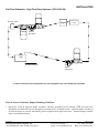
Any vacuum leaks between the fuel tank and lift pump will allow air to be drawn into the system. These leaks cause high and/or
fluctuating GPH readings. Only severe leaks affect engine performance, but all leaks affect sensor performance and instrument
readings. Vacuum or suction leaks occur at improperly sealed primary filters, loose packing nuts on cross over & shut off valves
and improperly sealed fittings. Vacuum leaks can also occur from corroded copper fuel lines and chaffed fuel hose, (where it rubs
against bulkheads or engine parts). To verify that a suction leak is present, temporarily insert a clear piece of fuel resistant tubing
downstream of the Forward Sensors’ outlet. Observe the clear hose for at least two minutes looking for bubbles. Bubbles can
appear as a constant stream of small bubbles, or as an occasional larger bubble. Tighten all possible leak sources, grease primary
filter seals and install fitting seals on JIC/SAE fittings. Continue to observe the clear tubing until it runs clear without any
bubbles. Flex or wiggle rubber hose sections while observing the clear tubing. If bubble volume increases inspect the hose and
check its fittings. Repair as necessary.
•
When idling in neutral, (No Load) GPH fluctuations can also be caused by the governor trying to maintain a steady engine RPM.
•
Calibration. When the system is running properly, refer to the calibration instructions and calibrate your system. If installed
properly, initial calibration takes much less than 1 hour. After consuming some fuel, final calibration should only take a few
minutes.
04/09/2008
FloScan Instrument Company, Inc.
3016 NE Blakeley Street, Seattle, WA 98105
2000-081-00
Tel: (206) 524-6625
Email: [email protected]
Fax: (206) 523-4961
Http://www.floscan.com