1
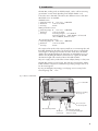
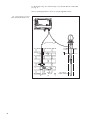
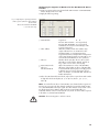
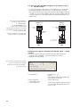
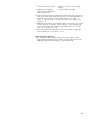
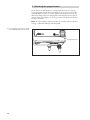
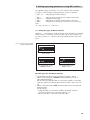
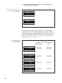
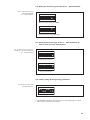
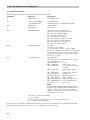
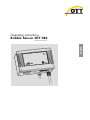
English
Operating instructions
Bubble Sensor OTT CBS
We reserve the right to make technical changes and improvements without notice.
Table of Contents
1 Scope of supply
4
2 Order numbers
4
3 Introduction
5
3.1 Function
3.2 Status LED
6
6
4 Installing OTT CBS
7
4.1 Preparing the OTT CBS for installation
4.2 Fastening OTT CBS
4.3 Connecting measuring tube to OTT CBS
5 Installing bubble chamber
9
5.1 Installing bubble chamber for surface water
5.2 Installing bubble chamber for ground water
6 Connecting OTT CBS
6.1
6.2
6.3
6.4
6.5
Connecting
Connecting
Connecting
Connecting
Connecting
power supply
the OTT CBS to
the OTT CBS to
the OTT CBS to
the OTT CBS to
7
7
8
9
10
12
any datalogger using an SDI-12 interface
any datalogger using a 4 … 20 mA interface
LogoSens 2 or DuoSens using an SDI-12 interface
LogoSens 2 or DuoSens using a 4 … 20 mA interface
13
13
13
14
16
7 Activating the purge function
18
8 Setting operating parameters using DIP switches
19
8.1
8.2
8.3
8.4
8.5
Setting the type of SDI-12 interface
Setting measurement type of the 4 … 20 mA interface to level or depth measurement
Scaling the measuring range for the 4 … 20 mA interface
Setting the measuring system for the 4 … 20 mA interface
Setting measurement type of the 4 … 20 mA interface to water
level or pressure measurement
8.6 Factory setting of the operating parameters
9 SDI-12 Commands and Response
9.1 Standard commands
9.2 Advanced SDI-12 commands
19
20
20
21
21
21
22
22
23
10 Determining the maximum load resistance at the
4 … 20 mA interface
24
11 Carrying out maintenance work
25
11.1 Activating purge function
11.2 Cleaning bubble chamber
11.3 Testing measuring tube
25
25
25
12 Status LED
26
13 Note about the disposal of old devices
26
14 Technical Data
27
3
1 Scope of supply
䊳 OTT CBS
–1 Bubble Sensor OTT CBS with possibility for connecting measuring tubes with
4 mm/2 mm external/internal diameter
–1 Installation kit (top hat rail with fastening parts; screw terminal blocks, pin jumpers)
–1 Operating Instructions
2 Order numbers
䊳 OTT CBS
Bubble Sensor OTT CBS
63.200.001.9.2
䊳 Accessories
Measuring tube
4 mm/2 mm external/internal diameter; transparent PE
– 50 m
– 100 m
99.420.050.9.5
99.420.100.9.5
Combined measuring tube/
bubble chamber suspension cable
black, with kevlar core for length stabilization, measuring tube
with 4 mm/2 mm external/internal diameter; transparent PE
– 50 m
– 100 m
99.420.009.9.5
99.420.008.9.5
Measuring tube
6 mm/4 mm with sheathing
Length as requested
20.500.133.5.5
Measuring tube
6 mm/4 mm without sheathing
Length as requested
20.500.302.5.5
Bubble chamber suspension cable
black, with Kevlar core for length stabilization
– 50 m
– 100 m
99.000.050.9.5
99.000.100.9.5
Bubble chamber for ground water
– for observation wells beginning at 2" diameter, 670 gram
55.510.051.4.2
Bubble Pot EPS 50 for surface water
– hose connector 4 mm/2 mm
– hose connector 6 mm/4 mm
55.510.048.3.2
55.510.049.3.2
Straight pipe fitting
– for connecting measuring tubes with
1/8" internal diameter and 3/8" external diameter
4
63.200.025.9.2
3 Introduction
The OTT CBS, working on the air bubble principle, can be used for measuring
ground water or water levels depending on the bubble chamber used.
To meet the various demands of the station, three different versions of the OTT
CBS bubble sensor are available:
Standard version:
䊳 Measuring range 0 … 15 m or 0 … 1500 mbar
䊳 Resolution
1 mm or 0.1 mbar
䊳 Accuracy
±5 mm
USGS specification version:
䊳 Measuring range 0 … 15 m or 0 … 1500 mbar
䊳 Resolution
1 mm or 0.1 mbar
䊳 Accuracy
measuring range 0 … 15 ft: ±0.01 ft
measuring range 15 … 50 ft: ±0.065 % of measured
value or ±0.02 ft, whichever is less
30 m measuring range version:
䊳 Measuring range 0 … 30 m or 0 … 3000 mbar
䊳 Resolution
1 mm or 0.1 mbar
䊳 Accuracy
±5 mm
The compressed air produced by a piston pump flows via a measuring tube and
the bubble chamber into the water to be measured. The pressure created in the
measuring tube is directly proportional to the water column above the bubble
chamber. The OTT CBS determines the barometric air and bubble pressure one
after the other. By taking the difference between the two signals, the OTT CBS
calculates the height of the water level above the bubble chamber.
The power supply can be provided from a mains adapter, battery or solar power.
The OTT CBS contains a purge function. This clears the measuring tube and the
bubble chamber of any minor contamination by pumping a large volume of air
into the measuring tube.
By using an intelligent pump strategy, no air drying unit is necessary for the
measuring range of 0 … 15 m.
Fig. 1: Overview of OTT CBS.
Status LED
Button for activating
the purge unit
Hose connection
for measuring tube
DIP switch compartment
Air filter for
incoming air
Terminal blocks A and B
for connecting the datalogger
and power supply
5
For the display of any error states that may occur, the OTT CBS has a Status LED
(see Fig. 1).
Various operating parameters can be set using the eight DIP switches.
Fig. 2: The main layout of a level
station with OTT CBS bubble sensor.
Measuring tube
Bubble pot
EPS 50
6
Groundwater
bubble chamber
4 Installing OTT CBS
4.1 Preparing the OTT CBS for installation
䡵 If necessary and you have not already done so: set operating parameters with
DIP switches (see Chapter 8).
4.2 Fastening OTT CBS
The OTT CBS is designed only to be installed on top hat rails (a section of top hat
rail is supplied with the OTT CBS). Choose a dry and dust free location for the
installation such as a gage station or control cabinet.
䡵 First attach the OTT CBS on the upper edge of the top hat rail and then press
the underside against the top hat rail until it clicks into place.
Demounting OTT CBS
䡵 First press one locking device downwards and pull the OTT CBS slightly forwards at this point. Press the second locking device downwards and remove
the OTT CBS upwards from the top hat rail.
Fig. 3: Fastening the CBS on the top
hat rail (left)/demounting (right).
Top hat rails
Locking device
7
4.3 Connecting measuring tube to OTT CBS
To install the measuring tube on the OTT CBS, proceed as follows:
Measuring tube with 2 mm internal diameter
䡵 Cut off the end of the measuring tube square with a sharp knife and push onto
the factory fitted connection nipple.
Maximum length of the measuring tube: 100 m.
Measuring tube with 4 mm internal diameter
䡵 Cut off the end of the measuring tube square with a sharp knife.
䡵 Remove cap nut (width across flats: 10) and pull off the (short) factory mounted
measuring tube from the connection nozzle.
䡵 Push cap nut over the measuring tube (Ø 4 mm).
䡵 Push measuring tube onto the connection nozzle.
䡵 Push the cap nut back onto the connection nozzle and tighten by hand.
Maximum length of the measuring tube: 75 m.
Measuring tube with 1/8" internal diameter
A special pipe fitting for the 1/8" internal diameter measuring tube is available
(accessory). Please follow the instructions delivered with the pipe fitting for
installing the pipe.
Maximum length of the measuring tube: 100 m.
Fig. 4: Connecting measuring
tube on OTT CBS.
Connection
nozzle
2.
1.
Cap nut
Connection nipple
Measuring tube
Ø: 2 mm
8
Measuring tube
Ø: 4 mm
5 Installing bubble chamber
Please ensure the following points are noted during installation:
䊳 No contamination or moisture may be allowed into the measuring tube.
䊳 When immersing the bubble chamber (only EPS 50), the OTT CBS must be
activated, so that the piston pump is operating during this process.
䊳 Do not damage or kink the measuring tube during installation.
䊳 Lay the measuring tube such that there is a continuous drop from the OTT CBS
towards the bubble chamber. Otherwise moisture could collect in a hollow and
potentially block the tube with the formation of drops (see Fig. 5)
Fig. 5: Routing requirements
for measuring tube.
Measuring tube
1" metal tube
Direction of flow
Bubble pot
EPS 50
5.1 Installing bubble chamber for surface water
We recommend using the Bubble Pot EPS 50 for measurements in surface waters.
See Bubble Pot EPS 50 installation instructions for information on its installation.
9
5.2 Installing bubble chamber for ground water
To install the bubble chamber for ground water, proceed as follows:
䡵 Determine depth of the bubble chamber (e.g. using a contact gauge). The
bubble chamber must be positioned under the lowest expected water level.
Depth = distance from bubble opening to upper edge of the
top cap
䡵 Push the measuring tube into the cable gland of the bubble chamber as far as
it goes.
䡵 Tighten the cable gland firmly by hand
䡵 Cut suspension cable to length; suspension cable length = depth +
125 cm (to protect the suspension cable from being twisted off, it can be
melted, with a cigarette lighter for example).
䡵 Feed the suspension cable through the hole in the bubble chamber as shown in
Figure 6 and tie firmly.
䡵 Slide cover into position B (upwards), see Fig. 6.
Fig. 6: Installing bubble
chamber for ground water.
When lowering the bubble chamber, the
cover must be in position B! The cover
prevents water entering the measuring
tube during installation.
Suspension cable
bubble chamber
Measuring pipe
During initial startup, over pressure builds
up in the measuring tube. As a result, the
cover falls back to position A and opens the
measuring tube in the process.
Cable
gland
Cover in
position B
Bubble opening
Cover in
position A
Metal pin
Hole
Bubble pot
10
䡵 As shown in Fig. 7, attach the suspension cable of the bubble chamber to the
retainer on an OTT top cap already mounted. The retaining plate allows a fine
height adjustment afterwards.
䡵 Secure the suspension cable against slipping with a knot.
䡵 If top caps without retainers are used, ensure the suspension cable is attached
securely.
䡵 Check all knots and attachments for correct position and firmness.
䡵 Lower the bubble chamber slowly into the observation well with the suspension
cable.
䡵 Feed the measuring tube out of the observation well through a hole.
Fig. 7: Installing bubble chamber for
ground water – attaching suspension cable.
Top cap
Retainer
Measuring tube
Retaining plate
Observation
well
Securing knot
Suspension cable
bubble chamber
11
6 Connecting OTT CBS
The OTT CBS has the following interfaces
䊳 SDI-12
䊳 4 … 20 mA (current loop)
䊳 RS-485, 2-wire (SDI-12 protocol via a physical RS-485 interface)
as well as a
䊳 connection for the power supply (UBat + GND).
The three interfaces make it possible to connect the OTT CBS both to OTT dataloggers and to any datalogger by another manufacturer that has the correct interfaces. The SDI-12 interface meets SDI-12 Standard 1.3 (SDI-12 = Serial-Digital
Interface with 1200 baud).
All electrical connections are made using two screw terminal strips (supplied) at
terminal blocks A and B on the underside of the OTT CBS.
Fig. 8: Assignments for the screw terminal
strips A and B of the OTT CBS.
Screw terminal strip
A
B
3
4
12
1
2
3
4
RS 485 A*
RS 485 B*
SDI-12 DATA
SDI-12 GND
2
+UBat
4 … 20 mA +
4 … 20 mA –
GND
1
* SDI-12 protocol via physical
RS-485 interface (for connecting to
OTT LogoSens and OTT DuoSens)
6.1 Connect power supply
The OTT CBS requires a power supply of 10 … 30 V DC, typ. 12/24 V DC (e.g.
using batteries or mains connection with galvanically separated low safety voltage).
Please note the following points when dimensioning the power supply:
䊳 Maximum power consumption per day: 3700 mAh (typ. 320 mAh/day) (with
1 min measurement interval and 100 m measuring tube using the 4 … 20 mA
interface)
䊳 Peak current consumption: temporary max. 2 A
䊳 Protect the supply voltage with a microfuse (e.g. 2.5 A, slow-blow)!
䊳 When using solar panels, we recommend the use of an overvoltage protection
device.
To supply the OTT CBS with power, proceed as follows:
䡵 Connect the power supply to screw terminal strip A of the OTT CBS as shown
in Fig. 8.
Notes
䊳 The OTT CBS does not have a switch for switching the unit on and off. As soon
as power is supplied, the OTT CBS is ready for operation.
䊳 Each time the power supply is attached, the piston pump operates for approx.
400 strokes (approx. 5 minutes running time).
6.2 Connecting the OTT CBS to any datalogger using an SDI-12
interface
䡵 Connect the OTT CBS to an SDI-12 input of the external datalogger. Follow the
datalogger handbook as you do this. See Fig. 8 for the assignments.
6.3 Connecting the OTT CBS to any datalogger using 4 … 20 mA
interface
䡵 Connect the OTT CBS to a 4 … 20 mA input of the external datalogger. Follow
the datalogger handbook as you do this as well as Chapter 10 of these instructions). See Fig. 8 for the assignments.
䡵 With depth measurement: ensure that DIP switch 4 is set to ON.
13
6.4 Connecting the OTT CBS to LogoSens 2 or DuoSens using an
SDI-12 interface
Method A: Connect the OTT CBS via the SDI-12 interface (protocol and physical
interface: SDI-12). The maximum length of the cable is 70 m. Recommended
cable cross-section: 0.25 mm2:
䡵 Connect the OTT CBS as shown in Figure 9 to the LogoSens 2 Station Manager
or to the DuoSens Compact Data Logger. Take note of the operating instructions
for the LogoSens 2/DuoSens.
LogoSens 2
4
1
2
3
4
SDI-12
input
1
2
3
4
4
3
0V
3
4
2
3
1
A
T
A…R
SDI-12
input
DuoSens
2
The letters above/below the screw terminal
strip identify the possible connections on
the LogoSens 2/DuoSens/CBS.
1
Fig. 9: Connecting the OTT CBS to LogoSens
2 or DuoSens using an SDI-12 interface.
1
2
B
B
CBS
CBS
Method B: Connect OTT CBS using the physical RS-485 interface (SDI-12 protocol via physical RS-485 interface). The maximum length of the cable is 1,500 m.
Recommended cable type: Unshielded twisted-pair cable; recommended cable
cross-section: 0.25 mm2:
䡵 Connect the OTT CBS as shown in Figure 10 to the LogoSens 2 Station Manager or to the DuoSens Compact Data Logger. Take note of the operating instructions for the LogoSens 2/DuoSens.
A…R
A
3
4
1
2
2
RS-485
input
1
2
4
1
3
4
3
14
RS-485
input
DuoSens
3
4
2
The letters above/below the screw terminal
strip identify the possible connections on
the LogoSens 2/DuoSens/CBS.
LogoSens 2
1
Fig. 10: Connecting the OTT CBS to
LogoSens 2 or DuoSens using an
RS-485 interface (SDI-12 protocol).
B
B
CBS
CBS
Configuring the LogoSens 2/DuoSens for the OTT CBS with SDI-12
interface
䡵 Create a LogoSens 2/DuoSens channel with SDI-12 Master or OTT SDI RS485
function block (serial sensors tab).
䡵 Apply the following settings:
Fig. 11: Adjusting the operating parameters
of the LogoSens 2/DuoSens SDI-12 Master
function block.
The function block OTT SDI RS485
is set in the same way.
䊳 Terminal block
䊳 Slave address
䊳 Value no.
䊳 Measurement mode
䊳 Value no./
Virtual Terminal ID
LogoSens 2:
A…R
DuoSens SDI-12 Master: A 3-4 (specified)
DuoSens OTT SDI RS485: A 1-2 (specified)
terminal block used (screw terminal strip) of the
LogoSens 2/DuoSens.
SDI-12 bus address. Each slave address may
only be allocated once to an SDI-12 bus line.
(checking/setting: see operating instructions
LogoSens 2/DuoSens, Chapter SDI-12 transparent
mode.) Typical setting: 0 (only one OTT CBS is connected to the terminal block; no bus operation).
Identifies which value (the xth of n values) of the
OTT CBS is recorded in this channel. Typical setting: 1 (first of seven values: level in [m])
M! (For the maximum 7 values of the OTT CBS).
Allocation of the further six values of the OTT CBS
to virtual terminals (level in [cm]; level in [ft]; pressure
in [mbar]; pressure in [psi]; temperature in [°C];
status; see Chapter 9, commands aM! and aV! for
further information).
䡵 In the relevant Channel function blocks, adjust to the required units and number
of digits after the decimal place (m: 3; cm: 0; ft: 2; mbar: 1; psi: 3; °C: 1;
status: 0).
Note: To record all seven values of an OTT CBS, seven channels in the LogoSens 2/
DuoSens are necessary. The first channel contains the function block SDI-12 Master or OTT SDI RS485 as the input signal. The other channels each contain a function block Virtual Sensor (V02 to V07) as the input signal. Naturally, just
individual channels can be recorded. In this case, there are fewer entries required
in the Value no./Virtual Terminal ID field.
Caution: The measuring time is at least 1 minute.
15
6.5 Connecting the OTT CBS to LogoSens 2 or DuoSens using a
4 … 20 mA interface
䡵 Connect the OTT CBS to the LogoSens 2 Station Manager or to the DuoSens
Compact Data Logger as shown in Figure 12. Take note of the operating
instructions for the LogoSens 2/DuoSens. Maximum cable length/recommended cable cross-section: Ensure that the ohm cable resistance together with any
resistor present does not exceed the maximum permitted load resistance (see
Chapter 10)!
A…R
C … F*
1
2
3
4 … 20 mA
input
4
1
2
4
4 … 20 mA
input
3
3
4
100 Ohm
resistor
* DuoSens with
analog extension only
+UBat
+UBat
GND
In the shown application the supply of the
current loop will occur via the OTT CBS.
GND
The letters above/below the screw terminal
strip identify the possible connections on the
LogoSens 2/DuoSens/CBS.
DuoSens
2
Use the 100 Ohm OTT resistor
(order number: 55.550.126.4.2)!
LogoSens 2
1
Fig. 12: Connecting the OTT CBS to
LogoSens 2 or DuoSens using a
4 … 20 mA interface.
1
2
3
A
A
CBS
CBS
4
Configuring the LogoSens 2/DuoSens for OTT CBS with 4 … 20 mA
interface
䡵 Create a LogoSens 2/DuoSens channel with function block I 4-20 mA
(LogoSens 2) or U/I/Pt100/… (DuoSens) (Analog sensors tab).
䡵 Apply the following settings:
Fig. 13: Setting operating parameters of the
LogoSens 2 I 4-20 mA function block.
The DuoSens function block U/I/Pt100/…
is set in the same way.
䊳 Terminal block
䊳 Measuring mode
LogoSens 2: A … R
DuoSens:
C ... F
terminal block used (screw terminal strip)
of the LogoSens 2/DuoSens.
Set to I 4-20 mA ext.
(only with DuoSens)
䊳 Sensor lag time (s)
16
switches on the LogoSens 2/DuoSens input
x seconds before the actual measurement
process; set to1
䊳 □ Error code if range overflow
䊳 Auxiliary sensor supply via
if required: record error codes if range
overflow
not required with an OTT CBS
relay contact at terminal block
(only for LogoSens 2)
䡵 Insert a function block 2-Point scaling into this channel and set the appropriate
water levels for the electrical values measured (e. g. for an OTT CBS with 15 m
measuring range and level measurement (DIP switches 5 + 6 = ON):
Point 1: 4 → 0; Point 2: 20 → 15). Ensure you note here the settings of DIP
switches 5 + 6!
䡵 With depth measurement: ensure that DIP switch 4 is set to ON or carry out the
inversion of the value via function 2-point scaling (e. g. for an OTT CBS with
15 m measuring range and depth measurement (DIP switches 5 + 6 = ON):
Point 1: 4 → 15; Point 2: 20 → 0).
䡵 In the relevant Channel function block, set the unit and number of digits after
the decimal place (m: 3; ft: 3; mbar: 1; psi: 3).
Note on points 6.2 to 6.5
䊳 To reference OTT CBS level/depth values to a level zero: Input the contact
gauge/staff gauge measurement, for example using the scaling function of the
datalogger connected to the OTT CBS (e. g. LogoSens/DuoSens).
17
7 Activating the purge function
On the front of the OTT CBS there is a Pump membrane button (see Fig. 14).
Pressing the button activates the purge function for as long as it is pressed. The
Status LED lights for approx. 2 seconds. With an activated purge function, the
CBS pumps a large amount of air through the measuring tube for the required
time period (see also Chapter 11). The purge function can also be activated via
an SDI-12 command.
Note: Press the membrane button for at least one second as otherwise the error
memory is called and displayed at the Status LED.
Fig. 14: Activating purge function manually
on the OTT CBS with membrane button.
Membrane button
18
8 Setting operating parameters using DIP switches
The eight DIP switches are behind a cover on the underside of the OTT CBS
(see Figure 1). The following operating parameters can be set with them:
䊳 DIP 1, 2, 3
Setting the type of SDI-12 interface
䊳
䊳
䊳
䊳
Setting measurement type as level or depth measurement*
Scaling measuring range *
Setting metric or imperial system (m/mbar or feet/psi) *
Setting measurement type as water level or pressure measure-
DIP 4
DIP 5 + 6
DIP 7
DIP 8
ment *
* these settings only affect the 4 … 20 mA interface.
8.1 Setting the type of SDI-12 interface
With DIP 1 … 3 select the type of SDI-12 interface of the OTT CBS (screw terminal
strip B; contacts 1 to 4). Please also take note that only one of the interfaces can
be used in each case: 4 … 20 mA or SDI-12 (no parallel operation of the interfaces).
Fig. 15: Setting the type of SDI-12
interface of the OTT CBS.
ON
1 2 3 4 5 6 7 8
SDI-12 interface
ON
ON
1 2 3 4 5 6 7 8
1 2 3 4 5 6 7 8
SDI-12 via RS-485 interface
without termination
SDI-12 via RS-485 interface
with termination
Possible types for the SDI-12 interface
䊳 Standard SDI-12 interface (protocol and physical interface: SDI-12)
䊳 SDI-12 via RS-485 interface without termination (SDI-12 protocol via
physical RS-485 interface).
Use this setting if multiple OTT CBS are connected in parallel to one RS-485
cable (bus operation) for all OTT CBS except the last device at the end of the
bus.
䊳 SDI-12 via RS-485 interface with termination (SDI-12 protocol via physical
RS-485 interface).
Use this setting if
– multiple OTT CBS are connected in parallel to the RS-485 cable (bus
operation) for the last device at the end of the bus, or if
– only one OTT CBS is connected to the RS-485 cable.
19
8.2 Setting measurement type of the 4 … 20 mA interface to
level or depth measurement
Fig. 16: Setting measurement type level
or depth measurement of the OTT CBS
(4 … 20 mA interface).
ON
1 2 3 4 5 6 7 8
Level Measurement
ON
1 2 3 4 5 6 7 8
Depth Measurement
8.3 Scaling the measuring range for the 4 … 20 mA interface
With DIPs 5 and 6 you can scale the available measuring range (15 or 30 m) of
an OTT CBS to a smaller range. Where the whole measuring range is not required,
this has the advantage that a higher resolution for the 4 … 20 mA interface can
be achieved. Example: For 2 m water level change 16 mA measuring range is
available (DIP switches 5 + 6 = OFF).
Fig. 17: Scaling the measuring
range of the OTT CBS
(4 … 20 mA interface).
CBS version
ON
Standard +
USGS specification
30 m measuring
range
15 m / 50 ft
1.5 bar / 25 psi
(not scaled)
30 m / 100 ft
3 bar / 50 psi
(not scaled)
8 m / 25 ft
0.8 bar / 12 psi
15 m / 50 ft
1.5 bar / 25 psi
4 m / 12 ft
0.4 bar / 6 psi
8 m / 25 ft
0.8 bar / 12 psi
2 m / 6 ft
0.2 bar / 3 psi
4 m / 12 ft
1.5 bar / 6 psi
1 2 3 4 5 6 7 8
ON
1 2 3 4 5 6 7 8
ON
1 2 3 4 5 6 7 8
ON
1 2 3 4 5 6 7 8
20
8.4 Setting the measuring system for the 4 … 20 mA interface
Fig. 18: Setting the measuring
system of the OTT CBS
(4 … 20 mA interface).
ON
1 2 3 4 5 6 7 8
Metric measurement system: m + mbar
ON
1 2 3 4 5 6 7 8
Imperial measurement system: feet + psi
8.5 Setting measurement type of the 4 … 20 mA interface to
water level or pressure measurement
Fig. 19: Setting measurement type to
water level or pressure measurement
(4 … 20 mA interface).
ON
1 2 3 4 5 6 7 8
Water level measurement
ON
1 2 3 4 5 6 7 8
Pressure measurement
8.6 Factory setting of the operating parameters
Fig. 20: Factory setting of the
operating parameters.
ON
1 2 3 4 5 6 7 8
䊳 Standard SDI-12 interface; level measurement; measuring range not scaled;
metric system; water level measurement.
21
9 SDI-12 Commands and Response
9.1 Standard commands
The following SDI-12 standard commands are implemented in the OTT CBS:
Command
Response
Description
a!
a<CR><LF>
Acknowledge active
aI!
allccccccccmmmmmm…
…vvvxxxx<CR><LF>
Send Identification
OTT CBS Response = 13OTT HACH CBS107
aAb!
b<CR><LF>
Change Address
?!
a<CR><LF>
Adress Query
aM!
atttn<CR><LF>*
Start measurement in normal mode.
The measured values are output as follows:
D0: Level [m]; resolution: 0,001 m
D1: Level [cm]; resolution: 1 cm
D2: Level [ft]; resolution: 0,01 ft
D3: Pressure [mbar]; resolution: 0,1 mbar
D4: Pressure [psi]; resolution: 0,001 psi
D5: Temperature [°C]; resolution: 0,1 °C
D6: Status (see command aV!)
aD0!
a<wert<CR><LF>
Send data.
The answer looks as follows:
a = device address <values> = pd.d = +1,000
(level value – maximum of 9 characters per value and
35 characters per query). If several measured values
are queried, it may be necessary to continue with further queries, e.g. aD1!.
aV!
atttn<CR><LF>*
Start verification.
The verification lasts 1 second and provides a value
representing the test result:
D0: a+0<CR><LF>:
no error
D0: a+1<CR><LF>:
level too low (< 5 cm)
D0: a+2<CR><LF>:
overload (measuring range
exceeded)
D0: a+4<CR><LF>:
power supply voltage too
low
D0: a+8<CR><LF>:
pump motor overloaded
D0: a+16<CR><LF>:
watchdog error
D0: a+256<CR><LF>: data memory defective
D0: a+512<CR><LF>: data bus defective
D0: a+1024<CR><LF>: analog converter defective
D0: a+2048<CR><LF>: measuring cell defective
more than one error:
sum of errors
Note:
Messages 256 to 2048 signify hardware problems
that can only be rectified by the OTT Repaircenter (see
chapter 11). In this case, send your OTT CBS to us.
Message 16 means that your unit has been restarted.
No intervention is necessary.
* The answers consist of the following:
a = device address
ttt = 001 = time in seconds until the sensor is ready again at the latest
n = 5 = number of measured values
More information on the SDI-12 standard commands can be found in the document SDI-12; A Serial-Digital Interface Standard for Microprocessor-Based Sensors; Version 1.3 (see Internet page www.sdi-12.org).
22
9.2 Advanced SDI-12 commands
All advanced SDI-12 commands begin with an O for OTT. With these commands, it is possible to configure the OTT CBS
through the transparent mode of a datalogger.
Command
Response
Description
aOXP<value>!
aOXP<value><CR><LF>
Activate purge function.
The parameter <value> represents the setting defined
as follows:
0 = purge function deactivated
1 = purge function activated
aOXG<value>! or aOXG!
a<value><CR><LF>
Set/query value for local gravitational constant.
Format: cbb.aaa
c:
Polarity (+ or –)
bb: Number before the decimal point
aaa: Number after the decimal point
aOXT<value>! or aOXT!
a<value><CR><LF>
Set/query value for local water temperature.
Format: cbb.aaa
c:
Polarity (+ or –)
bb: Number before the decimal point
aaa: Number after the decimal point
Notes on commands aOXG<value>! and aOXT<value>!
The probe either produces a value proportional to the pressure, or an actual water level compensated for the relative density
of the water.
The corrected water level measurement is calculated according to the following formula
Water level = mH2O pressure at 4 °C *
1
Water density
*
9.80665
Local gravitational constant
With: water density = –6.017777e–6 t2 + 0.0000408 t + 0.999841 and with t = temperature in °C
The OTT CBS can calculate the water density at any time using the value for the local water temperature. You can enter the
value for the local gravitational constant using the command aOXG<value>!.
Calculation of the correct value for the local gravitational constant
The gravitational acceleration at the earth's surface varies between 9.78036 m/s2 at the equator and 9.83208 m/s2 at the
poles. Also, it decreases by 0.003086 m/s2 for each kilometer above sea level. With the following formula the local gravitational constant g in m/s2 can be calculated:
g = 9.780356 * (1 + 0.0052885 sin2α –0.0000059 sin2 2α) –0.003086 h
where α is the degrees of latitude and h the height above sea level in km. (Jursa, A.S., Ed., Handbook of Geophysics and the
Space Environment, 4th ed., Air Force Geophysics Laboratory, 1985, pp. 14-17).
Example: Kempten (OTT)
At a height above mean sea level of 669 m (0.669 km) and a latitude of 47.71°, a local gravitational constant of 9.80659
m/s2results.
Note: The OTT CBS is preset to an average value for Germany (Kassel). The measurement deviation caused by gravitation is
±3 mm in Germany (Flensburg – Oberstdorf). This measurement error can be compensated by inputting the local gravitational constant.
23
10 Determining the maximum load resistance
at the 4 … 20 mA interface
The load resistance connected to the OTT CBS must not exceed a specific maximum value. This value depends on the level of the supply voltage of the OTT CBS.
If the load resistance is greater, the output current can no longer be evaluated.
Smaller load resistances are allowed.
䡵 Read off the maximum load resistance for your power supply from the
following diagram.
Example: Power supply 18 Volt → max. load resistance 450 Ohm.
The OTT CBS delivers an output current corresponding to the measured value
for a load resistance of up to 450 Ohm.
䡵 Dimension the connected electrical circuit accordingly. Check the input
resistance of the connected peripheral device for this purpose.
Fig. 21: Diagram to determine the
maximum load resistance as a
function of the power supply.
R
Ω
Minimum power supply: 10 V
Maximum power supply: 30 V
1000
Resistor tolerance: 0.1 %/15 ppm.
900
800
700
600
500
Example
400
300
200
100
0
10
24
15
20
25
30
U
V
11 Carrying out maintenance work
The OTT CBS bubble sensor itself is maintenance free. We recommend that the
measuring tube and bubble chamber are checked at regular intervals as described below and cleaned as required:
11.1 Activating purge function
Activate the purge function of the OTT CBS quarterly by pressing the membrane
button Pump (see also Fig. 14) and checking whether air bubbles rise out of the
bubble chamber. If not, check whether the bubble chamber is blocked, and/or
whether the measuring tube is leaking or blocked.
11.2 Cleaning bubble chamber
Check the bubble chamber quarterly for sand buildup and weed infiltration. For
light sand buildup, clean the bubble chamber using the purge function, and for
heavier buildup or weed infiltration clean the bubble chamber carefully manually
(do not change the position of the bubble chamber).
11.3 Testing the measuring tube
After 15 years' operation, test the measuring tube for tightness/pressure resistance roughly every 2 years.
Never open the housing of the OTT CBS! There are no adjustment or control
elements inside the housing!
In the case of device defects, contact the OTT Repaircenter:
OTT Hydromet GmbH
Repaircenter
Ludwigstrasse 16
87437 Kempten · Germany
Phone +49 831 5617-433
Fax
+49 831 5617-439
[email protected]
25
12 Status LED
For the display of any error states that may occur, the OTT CBS has a Status LED
on the front of the device (see Fig. 1).
The following error states can arise:
䊳
䊳
䊳
䊳
䊳
䊳
䊳
䊳
䊳
level too low (< 5 cm)
overload (measuring range exceeded)
power supply voltage too low
pump motor overloaded
watchdog error
data memory defective
data bus defective
analog converter defective
measuring cell defective
1
2
3
4
5
6
7
8
9
x
x
x
x
x
x
x
x
x
flash
flash
flash
flash
flash
flash
flash
flash
flash
The OTT CBS shows an error state when it arises and for approximately 2 minutes
after pressing the Pump membrane button.
The … defective error states signify hardware problems that can only be rectified
by the OTT Repaircenter (see chapter 11). The watchdog error error state means
that the OTT CBS has been restarted. No intervention is necessary.
Any error states arising can be displayed as follows:
䡵 Press Pump membrane button briefly (< 1 second; otherwise the purge function
is called) → the LED lights once for a longer period as confirmation → Pause →
1st error state arising (e.g. flashing once) → Pause → 2nd error state arising
(e. g. flashing three times) → Pause → … . The OTT CBS repeats all error states
arising for approx. two minutes.
Notes
䊳 Interrupt displaying error states: press membrane button briefly.
䊳 If no error state has arisen: the LED lights once for a longer period as con-
firmation.
13 Note about the disposal of old devices
In accordance with the European Union guideline 2002/96/EC, OTT takes back
old devices within the member countries of the European Union and disposes of
them in an appropriate way. The devices concerned by this are marked with the
symbol shown aside. For further information about the return procedure, please
contact your local sales contact. You will find the addresses of all sales partners in
the internet on www.ott-hydrometry.com. Please take into consideration also the
national implementation of the EU guideline 2002/96/EC of your country.
26
14 Technical Data
Measuring ranges
Standard + USGS specification version
30 m measuring range version
Resolution
Accuracy SDI-12 interface
Standard + 30 m measuring range version
USGS specification version
Accuracy 4 … 20 mA interface
Measuring dynamics (max. level change)
Units
Interfaces
Power supply
Current consumption
Query interval 1 min
Query interval 15 min
Dimensions L x W x H
operating/display elements
DIP switches
Pump membrane button
Status LED
Weight
Housing material
Type of protection
Temperature range
Operation
Storage
Relative humidity
0 … 15 m or 0 … 1500 mbar
0 … 50 ft or 0 … 25 psi
0 … 30 m or 0 … 3000 mbar
0 … 100 ft or 0 … 50 psi
1 mm or 0.1 mbar
0.01 ft or 0.001 psi
±5 mm
±0.02 ft
measuring range 0 … 15 ft: ±0.01 ft
measuring range 15 … 50 ft: ±0.065 % of measured value or
±0.02 ft, whichever is less
±0.1 % FS; TC 10 ppm/°C (at 20 °C)
1 m/min
m or ft; bar or PSI
4 … 20 mA, SDI-12, SDI-12 via RS-485
10 … 30 V DC, typ. 12/24 V DC
typ. 320 mAh / day (max. 3 700 mAh / day)
typ. 25 mAh / day (max. 300 mAh / day)
165 mm x 205 mm x 115 mm
setting operating parameters (eight)
Call purge function; display error status using LED
Display operating state/error status
approx. 1,500 g
ABS
IP 43
–20 … +60 °C
–40 … +85 °C
10 … 95 % not condensing
Measuring tube
internal diameter
Length
EMC limits
Resistance to electrostatic discharge (ESD)
Resistance to electromagnetic fields
Resistance to transient fields (burst)
Resistance to surge
Line-borne and radiated interference
Connection possibilities for 2 mm, 4 mm, 1/8"
2 mm, 1/8": max. 100 m
4 mm: max. 75 m
complies with EN 61000-4-2 degree of severity 2
(4 kV contact discharge)
complies with EN 61000-4-3 degree of severity 3 (3 V/m)
complies with EN 61000-4-4 degree of severity 5 (4 kV)
complies with EN 61000-4-5 degree of severity 5 (4 kV)
complies with EN 55022 Class B (30 … 1000 MHz)
27
OTT Hydromet GmbH
Document number
63.200.001.B.E 04-0211
Ludwigstrasse 16
87437 Kempten ⋅ Germany
Phone +49 831 5617-0
Fax
+49 831 5617-2 09
[email protected] · www.ott.com