1
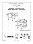
IMPINGER® CONVEYOR OVENS – MODEL SERIES 1400
UTILITY SPECIFICATIONS REQUIRED – ELECTRIC
Model
Energy
Power
Voltage
Current
Phase
Hz
***1421-xxx-E
Electric
27 kW
400/230 VAC
40 Amps
3
50 Hz
1452
Electric
27 kW
120/208 VAC
80 Amps
3
60 Hz
1453
Electric
27 kW
120/240 VAC
70 Amps
3
60 Hz
1454
Electric
27 kW
380/220 VAC
41 Amps
3
50 Hz
1455
Electric
27 kW
415/240 VAC
38 Amps
3
50 Hz
Recommended Electrical
Specifications
5 Wires, 3 Poles
1N-1G
5 Wires, 3 Poles
1N-1G
5 Wires, 3 Poles
1N-1G
5 Wires, 3 Poles
1N-1G
5 Wires, 3 Poles
1N-1G
Agency
Listing
F-G
A-B-D-F
A-B-D-F
F
F
UTILITY SPECIFICATIONS REQUIRED – GAS
Model
Energy
Power
Voltage
Current
Phase
Frequency
***1433-xxx-E
Nat. Gas
35 kW
230 VAC
3 Amps
1
50 Hz
***1434-xxx-E
L.P. Gas
35 kW
230 VAC
3 Amps
1
50 Hz
1450
Nat. Gas
1451
L.P. Gas
1456
Nat. Gas
1457
L.P. Gas
Agency
Listing
120,000
BTU
120,000
BTU
120,000
BTU
120,000
BTU
A
B
CSA
UL
120 VAC
120 VAC
220/240
VAC
220/240
VAC
5 Amps
1
60 Hz
5 Amps
1
60 Hz
5 Amps
1
50 Hz
5 Amps
1
50 Hz
C
Recommended
Electrical
Specification
3 Wires, 1 Pole
1N-1G
3 Wires, 1 Pole
1N–1G
3 Wires, 1 Pole
1N-1G
3 Wires, 1 Pole
1N-1G
3 Wires, 1 Pole
1N-1G
3 Wires, 1 Pole
1N-1G
Gas
35 kW/hr at 17.4
mB H2O column****
35 kW/hr at 27.4
mB H2O column****
Agency
Listing
F-G
F-G
120,000 BTU at 7
inches H2O column****
A-D-F
120,000 BTU at 11
inches H2O column****
A-F
120,000 BTU at 7
inches H2O column****
E-F
120,000 BTU at 11
inches H2O column****
E-F
D
E
F
G
MEA
AGA*
NSF
CE
H
Electrical Supply for Australia:
Single Phase: 240VAC, 50Hz / 20 Amp: one neutral & one earth/ground.
Three Phase: 240/415 VAC / 20 Amp; three active, one neutral & one earth/ground.
* AGA Australian Gas Association
*** Reference Model Key
** In Australia, use a 10 Amp General Purpose Outlet
All ovens require separate service and dedicated neutral.
GAS PRESSURE CONVERSION CHART
Inches of
Water Column
KPa
m-Bar
Millimeters of
Water Column
3.5
4.5
7
10
10.5
11
14
14.5
0.87
1.12
1.74
2.48
2.61
2.73
3.48
3.61
8.70
11.2
17.40
24.87
26.11
27.36
34.81
36.05
88.9
114.3
177.8
254.0
266.7
279.4
355.6
368.3
Impinger I – 1000 Series Operations Manual
****NOTE: For proper operation, the gas valve
requires a nominal inlet pressure of 7 inches H2O
column for natural gas and 11 inches of H2O column
for L.P. gas. A minimum inlet pressure of 1.0 inch of
H2O above the manifold setting (NAT. manifold 3.5”
H2O, L.P. manifold 10” H2O) must be maintained with
no pressure drop from the no load to full load
condition. The maximum inlet pressure must be
maintained at or below ½ PSIG (14.5 inches H2O
column). Refer to the chart on the left for pressure
conversions.
5