1
AIRCRAFT OPERATING INSTRUCTIONS
Light Sport Aircraft
T-LITE - CORE NANOLIGHT
st
Date: 1 November 2011
Approved:
Delegate of AirBorne WindSports Pty Ltd
Serial No.
Base
Serial No.
Wing
Registration
No.
This manual is compliant with the ASTM designation f2457 – 05 Standard specification for
required product information to be provided with weight-shift-control aircraft.
AirBorne WindSports Pty Ltd
UNIT 22/30 KALAROO ROAD, REDHEAD, NSW 2290 AUSTRALIA
Phone (02) 4944 9199 International +61 2 4944 9199
Fax (02) 4944 9395 International +61 2 4944 9395
E mail [email protected]
www.airborne.com.au
Part # 110788
©Copyright AirBorne WindSports Pty. Ltd. 2011
November 2011
Issue 1.0
Page 1
©
AirBorne WindSports Pty. Ltd.
SECTION 0
Aircraft Operating Instructions T-Lite - Core
This page left blank intentionally
November 2011
Issue 1.0
Page 2
©
AirBorne WindSports Pty. Ltd.
SECTION 0
Aircraft Operating Instructions T-Lite - Core
AIRCRAFT OPERATING INSTRUCTIONS – DETAILS
Issued By
Date
For AirBorne WindSports Pty. Ltd.
Table 1 Section 0. Aircraft Operating Instructions - Details
MANDATORY SERVICE BULLETINS
AS THE SERVICE HISTORY OF THE AIRFRAME EVOLVES AIRBORNE WILL FROM TIME TO
TIME ISSUE MANDATORY SERVICE BULLETINS, WHICH DETAIL ANY CHANGES TO THE
MAINTENANCE MANUALS, AIRCRAFT OPERATING INSTRUCTIONS, OR ANY OTHER DETAILS
THAT AIRBORNE DEEMS NECESSARY FOR OWNERS TO BE NOTIFIED OF.
THE WEB ADDRESS FOR SERVICE BULLETINS IS:
HTTP://WWW.AIRBORNE.COM.AU/
IT IS THE RESPONSIBILITY OF THE OPERATOR TO KEEP UP TO DATE WITH ANY ROTAX
DIRECTIVES THROUGH THE ROTAX WEBSITE.
November 2011
Issue 1.0
Page 3
©
AirBorne WindSports Pty. Ltd.
SECTION 0
Aircraft Operating Instructions T-Lite - Core
DATA PACKAGE
This Aircraft Operating Instructions constitutes one part of the complete data package that accompanies
the aircraft. Following is a list of each of the components, which are required.
• Aircraft Operating Instructions
+
• T-Lite Maintenance Manual
• T-Lite Illustrated Parts Catalogue
• Wing Maintenance Manual
• Wing Illustrated Parts Catalogue
• Engine Owners Manual
• TinyTach Manual
• Variometer Manual – If Installed
• Parachute Manual – If Installed
Table 2 Section 0. T-Lite Data Package
Certification documentation is held by the aircraft manufacturer,
Contact Information:
Airborne WindSports Pty Ltd
PO Box 7042 Redhead
NSW Australia 2290
Telephone +61 2 49449199
Web address: www.airborne.com.au
Or for recovery of the certification documentation, should the above contact not be available, contact the Civil
Aviation Safety Authority of Australia.
Website
http://www.casa.gov.au/
November 2011
Issue 1.0
Page 4
©
AirBorne WindSports Pty. Ltd.
SECTION 0
Aircraft Operating Instructions T-Lite - Core
AMENDMENT RECORD SHEET
Amendment Date
Affected Sections
Affected Pages
Date Inserted
Signature
Table 3 Section 0. Amendment Record Sheet
Manuals will be revised from time to time and re-issue of amended pages will be achieved by sending the
pages to the current owner registered on AirBorne’s database. Amendments will also be available on the
Airborne website (http://www.airborne.com.au/). The amended pages should be printed and the prior
page replaced in the manuals folder as soon as possible. The amendment table should at that time be
updated with the appropriate details and date.
November 2011
Issue 1.0
Page 5
©
AirBorne WindSports Pty. Ltd.
SECTION 0
Aircraft Operating Instructions T-Lite - Core
LOG OF EFFECTIVE PAGES
Page
Issue
Date
Page
Issue
Date
Page
Issue
Date
Table 4 Section 0. Log Of Effective Pages
November 2011
Issue 1.0
Page 6
©
AirBorne WindSports Pty. Ltd.
SECTION 0
Aircraft Operating Instructions T-Lite - Core
CONTENTS
1 GENERAL
2 LIMITATIONS
3 EMERGENCY PROCEDURES
4 NORMAL PROCEDURES
5 PERFORMANCE
6 WEIGHT BALANCE AND EQUIPMENT
7 AIRCRAFT & SYSTEMS DESCRIPTION
8 HANDLING SERVICE AND MAINTENANCE
9 SUPPLEMENTS
November 2011
Issue 1.0
Page 7
©
AirBorne WindSports Pty. Ltd.
SECTION 0
Aircraft Operating Instructions T-Lite - Core
This page left blank intentionally
November 2011
Issue 1.0
Page 8
©
AirBorne WindSports Pty. Ltd.
Aircraft Operating Instructions T-Lite - Core
SECTION 1
GENERAL
1 GENERAL ____________________________________________________________2
1.1 Introduction____________________________________________________________
NOTE ____________________________________________________________________
1.1.1 Warning Notice ______________________________________________________
1.1.2 Definitions __________________________________________________________
2
2
3
3
1.2 General Description _______________________________________________________
1.1.3 Two View Photos _____________________________________________________
1.1.4 General Dimensions___________________________________________________
1.1.5 General Description ___________________________________________________
4
4
5
5
1.2
Symbols Abbreviations and Terminology ___________________________________ 6
1.3
Use of Imperial / Metric Units______________________________________________ 8
November 2011
Issue 1.0
Page 1
©
AirBorne WindSports Pty. Ltd.
Aircraft Operating Instructions T-Lite - Core
SECTION 1
GENERAL
1 GENERAL
The Aircraft Operating Instructions (AOI) has various sections to comply with the ASTM standard. The
General Aviation Manufacturers Association (GAMA) format has been adopted and used where
applicable for this weight shift controlled nanolight.
This AOI contains information for the T-Lite base coupled with the Core wing. All relevant information is
supplied for this configuration.
1.1 Introduction
This nanolight series has been designed and manufactured in accordance with the ASTM designation
2317-04 Standard Specification for Design of Weight-Shift-Control Aircraft.
As an Australian Company, we are proud of our range of aircraft. Our microlights and nanolights have
been developed to provide the economy and durability required to meet the exacting demands of our
Australian conditions.
The success of our aircraft is based upon a high standard of product quality, innovative design
engineering and exceptional standards of reliability and performance that have been established since
1983.
Regular maintenance is required to keep your nanolight in a safe condition. Detailed maintenance
requirements are outlined in the wing and base maintenance manuals. Please reference these manuals
to ensure your nanolight is maintained correctly.
The AirBorne Team has developed from the long-standing friendship of a group of enthusiasts who share
conviction in the intrinsic advantages of weight shift controlled aircraft. The AirBorne Team is confident
your new nanolight will provide you with many years of enjoyable flying, and we wish you and your family
safe and happy flying for the future. The operating procedures outlined in this book are the result of
AirBorne’s knowledge and experience gained since 1983.
NOTE
AirBorne data packages will be revised from time to time. It is therefore important that owners promptly
notify Airborne of any changes to their contact details. Owners registered on AirBorne’s database will be
notified of any changes to data and directed to the AirBorne web site (http://www.airborne.com.au/) for
the applicable pages. The amended pages should be printed and the replacement pages inserted in the
folder as soon as possible. The amendment table should at that time be updated with the appropriate
details and date. Revised pages will be sent by mail if requested from AirBorne WindSports, the contact
details are at the front of this manual.
November 2011
Issue 1.0
Page 2
©
AirBorne WindSports Pty. Ltd.
Aircraft Operating Instructions T-Lite - Core
SECTION 1
GENERAL
1.1.1 Warning Notice
WARNING
OPERATIONS OUTSIDE THE RECOMMENDED FLIGHT ENVELOPE SUCH
AS AEROBATIC MANOEUVRES OR ERRATIC PILOT TECHNIQUE MAY
ULTIMATELY PRODUCE EQUIPMENT FAILURE RESULTING IN PERSONAL
INJURY OR DEATH. YOU ARE REFERRED TO THE OPERATING
LIMITATIONS IN SECTION 2 OF THIS MANUAL .
WARNING
THERE ARE INHERENT RISKS IN THE PARTICIPATION IN RECREATIONAL AVIATION AIRCRAFT.
OPERATORS AND PASSENGERS OF RECREATIONAL AVIATION AIRCRAFT, BY PARTICIPATION,
ACCEPT THE RISKS INHERENT IN SUCH PARTICIPATION OF WHICH THE ORDINARY PRUDENT PERSON
IS OR SHOULD BE AWARE. PILOTS AND PASSENGERS HAVE A DUTY TO EXERCISE GOOD JUDGMENT
AND ACT IN A RESPONSIBLE MANNER WHILE USING THE AIRCRAFT AND TO OBEY ALL ORAL OR
WRITTEN WARNINGS, OR BOTH, PRIOR TO AND DURING USE OF THE AIRCRAFT.
THE OWNER AND OPERATOR MUST UNDERSTAND THAT DUE TO INHERENT RISK INVOLVED IN
FLYING A MICROLIGHT/ULTRALIGHT/TRIKE/NANOLIGHT/POWERED HANG GLIDER, NO WARRANTY
IS MADE OR IMPLIED, OF ANY KIND, AGAINST ACCIDENTS, BODILY INJURY OR DEATH OTHER THAN
THOSE, WHICH CANNOT BY LAW BE EXCLUDED.
THE SAFE OPERATION OF THIS AIRCRAFT RESTS WITH YOU, THE PILOT.
WE BELIEVE THAT IN ORDER TO FLY SAFELY YOU MUST MATURELY PRACTICE AIRMANSHIP.
THE
SETTING
UP
AND
BREAKING
DOWN
OF
A
MICROLIGHT/ULTRALIGHT/TRIKE/
NANOLIGHT/POWERED HANG GLIDER, TRANSPORTATION AND FLYING WILL HAVE AN EFFECT OVER
TIME ON ITS STRUCTURAL INTEGRITY.
THE AIRCRAFT WILL REQUIRE MAINTENANCE AS OUTLINED IN THE APPLICABLE MAINTENANCE
MANUALS.
LIKE ANY AIRCRAFT, SAFETY DEPENDS ON A COMBINATION OF CAREFUL MAINTENANCE AND YOUR
ABILITY TO FLY INTELLIGENTLY AND CONSERVATIVELY.
WE HOPE THAT YOUR AIRCRAFT WILL PROVIDE YOU WITH MANY HOURS OF SAFE AND ENJOYABLE
FLYING.
1.1.2 Definitions
Definitions used in the Aircraft Operating Instructions such as WARNING, CAUTION and NOTE are
employed in the following context.
WARNING
OPERATING PROCEDURES, TECHNIQUES, ETC. WHICH IF NOT FOLLOWED CORRECTLY, MAY
RESULT IN PERSONAL INJURY OR DEATH.
CAUTION
OPERATING PROCEDURES, TECHNIQUES, ETC. WHICH IF NOT STRICTLY OBSERVED, MAY
RESULT IN DAMAGE TO THE AIRCRAFT OR ITS INSTALLED EQUIPMENT
NOTE
Operating procedures, techniques, etc. which it is considered essential to highlight.
November 2011
Issue 1.0
Page 3
©
AirBorne WindSports Pty. Ltd.
Aircraft Operating Instructions T-Lite - Core
SECTION 1
GENERAL
1.2 General Description
1.1.3 Two View Photos
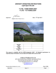
(T-Lite / Core shown in photographs)
Figure 1 Section 1. Aircraft Front View
Figure 2 Section 1. Aircraft Side View
November 2011
Issue 1.0
Page 4
©
AirBorne WindSports Pty. Ltd.
SECTION 1
GENERAL
Aircraft Operating Instructions T-Lite - Core
1.1.4 General Dimensions
1.1.4.1 T-Lite / Core
Metric
DIMENSIONS
Wing Span
Wing Area
Aspect Ration
Wing Weight
Overall Height (Control Bar Fwd)
Trike Width
Trike Length
Wheel Track
Wheel Base
Trike Height
Cockpit Width
Wing (Packed) Length
Wing Length (Short Packed)
9.5 m
15.60 sq m
5.7
34 kg
3.45 m
1.25 m
2.22 m
1.15 m
1.65 m
2.18 m
0.54 m
5.7 m
4.1 m
Imperial
31.1 ft
168 sq ft
75 lbs
11.3 ft
4.10 ft
7.28 ft
3.77 ft
5.41 ft
7.15 ft
1.77 ft
18.7 ft
13.5 ft
Table 1 Section 1. General Dimensions T-Lite / Core
1.1.5 General Description
1.1.5.1 Base
Designed to be an easily portable aircraft that is used for soaring, thermalling and general flying, the TLite provides the pilot with a very small, compact trike base that folds up to fit in the back of a station
wagon.
The T-Lite is a singe seat weight-shift controlled aircraft base. The wheels of the base are of tricycle
configuration with a single, steerable wheel at the front. There is an optional brake. The pilot sits in front
of the engine, and the propeller is in a pusher configuration. The passenger pod is suspended in a
triangular frame that is hinged at the top around the pitch and roll axes to provide weight-shift control.
The cockpit is very minimal, consisting of footpegs, an upholstered seat and harness, with the only
standard instrumentation being an engine rpm/hour meter, an airspeed indicator, and optional altimeter
depending on local requirements. This cockpit configuration is designed to match suitable wings. Any
wing used must be suitably matched, and tested for suitability by a qualified person.
November 2011
Issue 1.0
Page 5
©
AirBorne WindSports Pty. Ltd.
Aircraft Operating Instructions T-Lite - Core
SECTION 1
GENERAL
1.1.5.2 Wing
Using the Sting 3 hang glider as a design base, the Core wing has been engineered to handle additional
loads with MTOW 210kg. Similar to the Sting 3, the Core has great handling at low speed allowing very
easy control authority right up to touch down, and takes advantage of that wing’s excellent climbing and
general flying characteristics.
An excellent sail “fit” produces a wing that has light handling with impressive “feel” in turbulence. The
batten ends are a threaded clip design, which can be adjusted to vary tension for tuning the wing. The
batten mechanism allows easy installation and removal of the battens. An airfoiled aluminium section is
used for the down tubes and king post. Hardware is designed using state of the art engineering tooling
that provides fittings that look smart and are positioned to achieve minimum drag.
1.1.5.3 Base and Wing
Combining the T-Lite base with the Core wing results in an aircraft that offers hang gliding, paragliding
and trike flight characteristics, with the benefit of self-launching in nil to moderate wind, in a comfortable
seated position, that packs away to be fit on top of a normal sedan.
1.2 Symbols Abbreviations and Terminology
In this book:
“AOI” means Aircraft Operating Instructions
“Airfield Pressure Altitude or QNE” means the altitude of the airfield as indicated on an altimeter
with the subscale adjusted to 1013.2 millibars or hectopascals.
“AUW” (All Up Weight) means the weight of the aircraft including occupants, fuel quantity, engine
fluids, and removable and disposable equipment.
“CG” means the Centre of Gravity.
“Empty Weight” Refer to the note at Section 6.2 for the defined empty weight.
“FAA” United Stated Federal Aviation Administration
“fpm” means feet per minute.
“HGFA” means the Hang Gliding Federation of Australia.
“KCAS” means Knots Calibrated Airspeed
“KIAS” means Knots Indicated Airspeed as displayed on the cockpit mounted airspeed indicator.
“kg” means weight in kilograms.
“km/hr” means kilometres per hour.
“kts” means knots.
“Landing Approach Speed” means the airspeed that allows control in turbulence, wind gradient or
sudden engine failure during landing.
“L/hr” means litres per hour.
“Manoeuvring Speed” means the indicated airspeed above which the pilot may not make full or
abrupt control movements.
“mph” means miles per hour.
“QNH” means the pressure setting, that if set on the subscale of a sensitive altimeter, will cause the
altimeter to indicate the correct local altitude above mean sea level.
“RA-Aus” means the Recreational Aviation Australia.
November 2011
Issue 1.0
Page 6
©
AirBorne WindSports Pty. Ltd.
Aircraft Operating Instructions T-Lite - Core
SECTION 1
GENERAL
“Stall Speed” means the indicated airspeed at which an uncontrolled downward pitching motion of
the aircraft occurs or the forward control bar limit is reached.
“Take Off Safety Speed” means the airspeed that allows control in turbulence, wind gradient or
sudden engine failure during the climb following take-off.
“Trim Speed” means the indicated airspeed at which the aircraft remains in a stabilised condition
without pilot input.
“Va” means the aircraft stall speed.
“Va” means the aircraft stall maximum rough air speed.
“Vd” means the aircraft design diving speed.
“Vh” means maximum level speed.
“VNE” means the indicated airspeed that the aircraft is never to exceed.
“VSUSP” means maximum suspended weight
November 2011
Issue 1.0
Page 7
©
AirBorne WindSports Pty. Ltd.
SECTION 1
GENERAL
Aircraft Operating Instructions T-Lite - Core
1.3 Use of Imperial / Metric Units
This AOI uses the metric unit system as the basic system of measurement. Where common usage or
available instrumentation refer to the Imperial system both units are quoted. The following conversion
factors are presented as a ready reference to the conversion factors that have been used in this manual.
1 Pound (Ib)
=
0.4536 Kilogram (kg)
1 Pound per sq inch (psi)
=
6.895 Kilopascal (kPa)
1 Inch (in)
=
25.4 Millimetres (mm)
1 Foot (ft)
=
0.3048 Metre (m)
1 Statute mile
=
1.609 Kilometres (km)
1 Nautical mile (NM)
=
1.852 Kilometres (km)
1 Millibar (mb)
=
1 Hectopascal (hPa)
1 Millibar (mb)
=
0.1 Kilopascal (kPa)
1 Imperial gallon
=
4.546 Litres (I)
1 US gallon
=
3.785 Litres (I)
1 US quart
=
0.946 Litre (I)
1 Cubic foot (ft3)
=
28.317 Litres (I)
1 Degree Fahrenheit (F)
=
(1.8 X C)+32
1 Inch Pound (in Ib)
=
1 Foot Pound (ft Ib)
=
0.113 Newton Metres
(Nm)
1.356 Newton Metres
(Nm)
Table 2 Section 1. Imperial / Metric Conversion Factors
November 2011
Issue 1.0
Page 8
©
AirBorne WindSports Pty. Ltd.
Aircraft Operating Instructions T-Lite - Core
SECTION 2
LIMITATIONS
LIMITATIONS
LIMITATIONS ___________________________________________________________1
2 LIMITATIONS _________________________________________________________2
2.1
General _______________________________________________________________ 2
2.2
Airspeed Limitations ____________________________________________________ 2
2.3
Airspeed Indicator markings ______________________________________________ 2
2.4 Power Plant Limitations __________________________________________________
2.4.1 Engine _____________________________________________________________
2.4.2 Engine Limitations ____________________________________________________
2.4.3 Fuel Grades _________________________________________________________
2.4.4 Lubricating Oil _______________________________________________________
2.4.5 Drive Belt ___________________________________________________________
2.4.6 Propeller____________________________________________________________
2.5
2
2
3
3
3
3
4
Weight Limits __________________________________________________________ 4
2.6 Operational Limits ______________________________________________________
2.6.1 Centre of Gravity limits _________________________________________________
2.6.2 Manoeuvring Limits ___________________________________________________
2.6.3 Bank Angle__________________________________________________________
2.6.4 Flight Load Factor Limits _______________________________________________
2.6.5 Flight Crew Limits_____________________________________________________
2.6.6 Kinds of Operation Limits _______________________________________________
2.6.7 Fuel Limitations ______________________________________________________
2.6.8 Maximum Passenger Seating Limits ______________________________________
2.6.9 Minimum Pilot Weight _________________________________________________
2.6.10
Other Limitations____________________________________________________
4
4
5
5
5
5
5
5
5
5
6
2.7 Placards_______________________________________________________________ 7
2.7.1 Flight Limitations Placards ______________________________________________ 7
2.7.2 Flight Limitations Placard Locations_______________________________________ 8
2.7.3 Aircraft Operating Instructions Placard applicable for LSA _____________________ 9
2.7.4 Wing Vne ASI Placard _________________________________________________ 10
2.7.5 Fuel Type and Fuel Isolation Placard_____________________________________ 11
2.7.6 Ignition Placard _____________________________________________________ 12
2.7.7 Earth Placard _______________________________________________________ 12
2.7.8 Check Oil Placard ___________________________________________________ 13
2.7.9 Clear Prop Placard___________________________________________________ 14
2.7.10
Wing and Base Data Plates __________________________________________ 15
2.7.11
Under Seat Bag Placard _____________________________________________ 16
November 2011
Issue 1.0
Page 1
©
AirBorne WindSports Pty. Ltd.
SECTION 2
LIMITATIONS
Aircraft Operating Instructions T-Lite - Core
2 LIMITATIONS
2.1 General
The limitations section of this AOI outlines the various operating limitations, instrument function and
placards necessary for the safe operation of this aircraft, engine and standard equipment.
2.2 Airspeed Limitations
2.2.0.1 T-Lite Core
Speed
IAS
Comments
mph
km/hr
knots
Never Exceed
Speed (Vne)
53
85
46
Do not exceed this speed in any
operation
Maximum
Manoeuvring
Speed (Va)
39
63
34
Do not make full or abrupt control
movements above this speed
Table 1 Section 2. Airspeed Limitations
2.3 Airspeed Indicator markings
The Hall airspeed indicator that mounts on the control bar has a black on yellow placard with Vne marked
for the Core wing. The pilot should be aware of the combination of wing and base and be familiar with the
appropriate Vne marking.
2.4 Power Plant Limitations
2.4.1 Engine
Manufacturer:
Baileys
Model:
4V-200
Reduction ratio:
3.2 : 1
November 2011
Issue 1.0
Page 2
©
AirBorne WindSports Pty. Ltd.
Aircraft Operating Instructions T-Lite - Core
SECTION 2
LIMITATIONS
2.4.2 Engine Limitations
ENGINE LIMITATIONS
ENGINE SPEED
Take Off
Maximum Continuous
PERFORMANCE
Take -off Performance
AMBIENT START & OPERATING TEMPERATURE
Maximum
Minimum
Metric
Imperial
8200 rpm
7800 rpm
8200 rpm
7800 rpm
16.4 kW
22 hp
40 deg C
0 deg C
104 deg F
32 deg F
Table 2 Section 2. Engine Limitations
2.4.3 Fuel Grades
FUEL
Preferred Fuel Type
Leaded or Unleaded minimum 98 Octane
Optional Fuel Type
The engine is capable of running on lower than 98 octane fuel
rating but requires modification to the ignition timing and there will
be a slight reduction in power. Contact Bailey Aviation for details.
Table 3 Section 2. Fuel Specification
NOTE
Refer to section 2.6.7 for fuel capacities and limitations
2.4.4
Lubricating Oil
The Baileys engine uses a minimum amount of oil to conserve weight but is also used for engine cooling
so oil levels and change intervals are very important. Consult the Bailey manual for the correct type and
grade of oil for the ambient operating temperature.
The specified oil is:
Castrol Power 1 Racing Motorcycle Oil 5W-40 fully synthetic.
OR
Shell Advance Ultra4 SAE 10W-40
NOTE
Strict adherence to oil type is recommended.
Check oil and replenish as required. Consult the Bailey engine manual for maintaining the oil and oil
level.
Use caution around the hot exhaust when removing the oil top-up cap.
2.4.5 Drive Belt
Minimum drive belt tension is required to prevent slippage although some slippage at idle is normal and
is confirmed by hearing an occasional chirping noise. Drive belt defection of 5-8mm is optimum; consult
the engine manual for the drive belt checking and adjustment procedure.
November 2011
Issue 1.0
Page 3
©
AirBorne WindSports Pty. Ltd.
SECTION 2
LIMITATIONS
Aircraft Operating Instructions T-Lite - Core
2.4.6 Propeller
The T-Lite propeller is a two-piece, two-bladed propeller. The two halves of the propeller form the hub
once the propeller is fitted.
The propeller is fitted by slotting the two halves together. The propeller is then fitted onto the locating
pins, ensuring the T-Lite stickers on each blade face rearward. The wash plate is then fitted and the
securing bolt is then tightened and retaining pin fitted.
NOTE
Do not over-tighten the securing bolt. Tighten approx. ¼ turn after firm to line up with the slots on the
wash plate.
2.5 Weight Limits
Metric
Imperial
210 kg
463 lb
90 kg
198 lb
122.3 kg
270 lb
50-100 kg
110-220 lb
2kg
4 lb
Max take off weight
Typical empty weight
*1
Maximum empty weight
*2
Permitted range of pilot weight
Maximum behind seat storage load per bag
Table 4 Section 2. Weight Limits
*1
*2
Includes 0.5 litres (0.4kg) unusable fuel and Core wing (34kg). Empty weight is defined in section 6.2.
Includes 0.5 litres (0.4kg) unusable fuel and 86kg pilot. Empty weight is defined in section 6.2.
2.6 Operational Limits
2.6.1 Centre of Gravity limits
Centre of gravity limits are not critical on the base of a flex wing microlight. Having the trike unit attached
to the wing from a single universal bracket, variations of cockpit loading and fuel loading cannot influence
the aircraft’s balance. The T-Lite is therefore not critical in regards to centre of gravity although the
distribution of load in the trike base has a minor affect on the in-flight attitude of the trike base.
Base Suspension Range
Dimension
Dimension
Metric
Imperial
1635 mm +0/-15mm
64.37" +0/0-.59"
(Measured from the line joining the leading
edge nose bolts to the suspension point.)
CORE wing
Table 5 Section 2. Centre of Gravity Limits
NOTE
The front or rear hole of the U-bracket may be used as the suspension point for your aircraft, depending
on test flight results. Check with your dealer or Instructor for confirmation of which hole to use.
November 2011
Issue 1.0
Page 4
©
AirBorne WindSports Pty. Ltd.
SECTION 2
LIMITATIONS
Aircraft Operating Instructions T-Lite - Core
2.6.2 Manoeuvring Limits
All aerobatic manoeuvres including spinning are prohibited.
Aerobatic manoeuvres including whipstalls, stalled spiral descents and negative “G” manoeuvres are not
permitted. It must be emphasised that a whipstall, spiral descent or negative G manoeuvre can never be
conducted safely. These manoeuvres put the aircraft outside the pilot’s control and put both the aircraft
and its occupant in extreme danger.
Do not pitch nose up or nose down more than 45 degrees from the horizontal. The front support tube of
the trike and the pilot's chest limits the fore and aft movement of the control bar respectively.
2.6.3 Bank Angle
Do not exceed 60 degrees of bank angle. In roll there is no stop for the control movement. For the
purpose of pre-flight freedom, check by lowering each wing to within 10 cm off the ground (on ground
level).
2.6.4 Flight Load Factor Limits
Max positive manoeuvring load
factor
Negative load factors
4.0 G
Prohibited
Load factors below 1.0 G
To be avoided
Table 6 Section 2. Flight Load Factor Limits
2.6.5 Flight Crew Limits
Minimum and maximum flight crew is 1 person.
2.6.6 Kinds of Operation Limits
The aircraft is only to be flown under visual flight rules (VFR), and the minimum equipment required to
operate under VFR conditions are an air speed indicator and instruments required by the engine
manufacturer.
In Australia, when operated at a public aerodrome or on a cross-country flight, a compass and reliable
time piece are required. Additional equipment may be required for some overseas operations.
2.6.7 Fuel Limitations
Maximum Usable Fuel
9.5 litre
2.5 US Gal
Unusable Fuel capacity
0.5 litre
0.13 US Gal
Table 7 Section 2. Fuel Limitations
2.6.8 Maximum Passenger Seating Limits
No passenger allowed.
2.6.9 Minimum Pilot Weight
The nanolight aircraft must only be flown solo. Minimum pilot weight shall not be below 50 kg.
November 2011
Issue 1.0
Page 5
©
AirBorne WindSports Pty. Ltd.
SECTION 2
LIMITATIONS
Aircraft Operating Instructions T-Lite - Core
2.6.10 Other Limitations
Maximum Cross Wind
13 mph
plus gust
11 knots
plus gust
20 km/hr
plus gust
Maximum Wind Strength
17 mph
plus gust
15 knots
plus gust
28 km/hr
plus gust
Maximum Ambient
Operating Temperature
104 deg F
40 deg C
Table 8 Section2. Other Limitations
NOTE
A maximum gust factor of 3 – 5 knots is nominated to cover the range of expected pilot experience and
skill. Less experienced pilots should use the lower limits.
The skill of the pilot and the “quality” of the wind must be taken into account when assessing conditions
for flight, for example, a new pilot with minimal exposure to thermic and/or gusty conditions may find flight
conditions more appropriate in smooth consistent light breezes with little to no gust; while a pilot with
many hours experience of flying in rough conditions may assess conditions of moderate winds with
varying gust to be within his and the aircraft’s abilities.
No person who is untrained or unqualified in weight shift controlled flight or, who is unfamiliar with the
wing and base combination, should ever attempt to pilot the aircraft unless under professional instruction.
The effect of light rain on the aircraft can increase the stall speed. It is extremely important to maintain
speeds in excess of the take off and landing safety speeds when the wing is wet. If the aircraft has been
left out in the rain or heavy dew it is necessary to wipe the wing down prior to take off. A chamois or
sponge is recommended to remove the water.
Continued operation in heavy rain is not
recommended due to the abrasive effect of raindrops
on the propeller. Do not use waterproofing agents on
the wing as the consequent beading of water
droplets can significantly increase the stall speed.
November 2011
CAUTION
MOISTURE
ON
THE
WING
CAN
INCREASE STALL SPEED AND SHOULD
BE REMOVED PRIOR TO TAKE OFF.
Issue 1.0
Page 6
©
AirBorne WindSports Pty. Ltd.
Aircraft Operating Instructions T-Lite - Core
SECTION 2
LIMITATIONS
2.7 Placards
The placards on the aircraft are designed to provide information regarding general aircraft limitations and
other details for the safe operation of the aircraft. Listed on the following pages are details of the placards
fitted to the aircraft.
2.7.1 Flight Limitations Placards
Location
Series
The flight limitations placards are located along the trike base
tube. Loading limitations placard option of metric 110760 or
imperial 110761
T-Lite Series
Table 9 Section 2. Flight Limitations Placards
November 2011
Issue 1.0
Page 7
©
AirBorne WindSports Pty. Ltd.
Aircraft Operating Instructions T-Lite - Core
SECTION 2
LIMITATIONS
2.7.2 Flight Limitations Placard Locations
Figure 1 Section 2. Warning and flight limitations placard locations.
Figure 2 Section 2. Loading and engine limitations placard locations.
November 2011
Issue 1.0
Page 8
©
AirBorne WindSports Pty. Ltd.
Aircraft Operating Instructions T-Lite - Core
SECTION 2
LIMITATIONS
2.7.3 Aircraft Operating Instructions Placard applicable for LSA
Location
Series
The aircraft operating instructions placard 110766 is located on the right
hand side of the mast above the mast block. The aircraft type and fuel
capacity are combined on one placard and there are options for metric,
placard 110758, and imperial, placard 110759. This placard is mounted
below the AOI placard. The airworthiness placard 110764 is used on
Australian LSA and is located on the left hand side of the mast above the
mast block.
T-Lite Series
Table 10 Section 2. Aircraft operating instructions, aircraft type & fuel capacity, and LSA placard
locations.
Figure 3 Section 2. Aircraft operating instructions, aircraft type & fuel capacity, and LSA placard
locations.
November 2011
Issue 1.0
Page 9
©
AirBorne WindSports Pty. Ltd.
Aircraft Operating Instructions T-Lite - Core
SECTION 2
LIMITATIONS
2.7.4 Wing Vne ASI Placard
Location
Series
The Vne placard 110835 is located on the Hall air speed indicator and is mounted
on the left side of the wing control bar.
T-Lite Series
Table 11 Section 2. Wing Vne ASI placard
Figure 4 Section 2. Wing Vne placard locations.
November 2011
Issue 1.0
Page 10
©
AirBorne WindSports Pty. Ltd.
Aircraft Operating Instructions T-Lite - Core
SECTION 2
LIMITATIONS
2.7.5 Fuel Type and Fuel Isolation Placard
Location
Series
The fuel type / isolation placard is adjacent to the fuel valve at the top of
the seat frame on the left side of the aircraft. Metric part number is
110767, imperial is 110768.
T-Lite Series
Table 12 Section 2. Fuel type / isolation placard
Figure 5 Section 2. Fuel tap / isolation placard locations.
November 2011
Issue 1.0
Page 11
©
AirBorne WindSports Pty. Ltd.
Aircraft Operating Instructions T-Lite - Core
SECTION 2
LIMITATIONS
2.7.6 Ignition Placard
Location
Series
The ignition placard 110773 is located on the right side of the base
tube near the seat front, above the start button.
T-Lite Series
Table 13 Section 2. Ignition placard
Figure 6 Section 2. Ignition placard locations.
2.7.7 Earth Placard
Location
Series
The engine earth placard is located on the rear of the trike under
the engine at the bottom of the engine mounting bracket.
T-Lite Series
Table 14 Section 2. Earth placard
November 2011
Issue 1.0
Page 12
©
AirBorne WindSports Pty. Ltd.
Aircraft Operating Instructions T-Lite - Core
SECTION 2
LIMITATIONS
Figure 7 Section 2. Earth placard location.
2.7.8 Check Oil Placard
Location
Series
The check oil placard is located on the oil tank on the right side of
the engine. It is supplied with the engine.
T-Lite Series
Table 15 Section 2. Check oil placard
Figure 8 Section 2. Check oil placard location.
November 2011
Issue 1.0
Page 13
©
AirBorne WindSports Pty. Ltd.
Aircraft Operating Instructions T-Lite - Core
SECTION 2
LIMITATIONS
2.7.9 Clear Prop Placard
Location
Series
The clear prop placard is located on the right and left side wheel
struts
T-Lite Series
Table 16 Section 2. Clear prop placard
Figure 9 Section 2. Clear prop placard location.
November 2011
Issue 1.0
Page 14
©
AirBorne WindSports Pty. Ltd.
Aircraft Operating Instructions T-Lite - Core
SECTION 2
LIMITATIONS
2.7.10 Wing and Base Data Plates
XX-XXX
WING PLATE PART NO 102358
Location
Series
The wing data plate 102358 is located on the universal bracket
on the wing. The base data plate is located on the engine mount
on the left side of the aircraft.
T-Lite base and Core wing
Table 17 Section 2. Data plates
Figure 10 Section 2. Data plate placard locations.
November 2011
Issue 1.0
Page 15
©
AirBorne WindSports Pty. Ltd.
Aircraft Operating Instructions T-Lite - Core
SECTION 2
LIMITATIONS
2.7.11 Under Seat Bag Placard
Location
Series
The under seat placard is located under and behind the front
seat.
T-Lite Series
Table 18 Section 2. Under seat bag placard
Figure 11 Section 2. Under seat bag placard location.
November 2011
Issue 1.0
Page 16
©
AirBorne WindSports Pty. Ltd.
Aircraft Operating Instructions T-Lite - Core
SECTION 3
EMERGENCY
EMERGENCY PROCEDURES
EMERGENCY PROCEDURES______________________________________________1
3
EMERGENCY PROCEDURES___________________________________________2
3.1
General _______________________________________________________________ 2
3.2 Airspeeds for Emergency Operations ______________________________________ 2
3.2.1 T-Lite / Core _________________________________________________________ 2
3.3 Emergency Procedures Check List ________________________________________
3.3.1 Engine Failure on Climb Out ____________________________________________
3.3.2 Engine Failure at Height________________________________________________
3.3.3 Full Power Engine Shutdown (In Flight) ____________________________________
3.3.4 Forced Landings _____________________________________________________
3.3.5 In Air Engine Fire _____________________________________________________
3.3.6 On Ground Engine Fire ________________________________________________
3.3.7 Propeller Damage ____________________________________________________
3.3.8 Sail Damage ________________________________________________________
3.3.9 Emergency Parachute _________________________________________________
3.3.10
Ignition Circuit Failure ________________________________________________
3.3.11
Spins and Spiral Descents ____________________________________________
3.3.12
Unusual Attitudes ___________________________________________________
3.3.13
Instrument Failure ___________________________________________________
November 2011
Issue 1.0
3
3
3
3
3
4
5
5
5
5
6
6
6
7
Page 1
©
AirBorne WindSports Pty. Ltd.
Aircraft Operating Instructions T-Lite - Core
3
SECTION 3
EMERGENCY
EMERGENCY PROCEDURES
3.1 General
This section of the AOI describes the procedures to be adopted in the event of an emergency or
abnormal situation occurring in this aircraft.
These procedures are arranged in the sequence considered to be the most desirable in the majority of
cases. Steps should be performed in the order listed unless a suitable reason to deviate exists.
This section contains operating procedures for flight and system emergency conditions that are essential
for the continued safe operation of the aircraft.
Always maintain correct airspeed and altitudes in the circuit area.
Never fly in uncertain weather conditions and always fly within your proven ability. Be sure only to extend
your capabilities under planned training situations.
Carry out safe airmanship whilst flying and be aware of possible emergency landing areas along your
flight path. If possible check these areas from the ground as you enter the airfield or flying site. This
technique is for safety reasons as engines are susceptible to stopping, no matter how reliably
manufactured or maintained.
Keep a good lookout for other aircraft, always be thoughtful and show your intentions. Demonstrate good
airmanship always!
It should be remembered that the manufacturer cannot foresee all conceivable circumstances. Particular
circumstances such as multiple or unanticipated emergencies, adverse weather etc. may require
modification to these procedures. A thorough knowledge of the aircraft and its systems is required to
analyze the situation correctly and to determine the best course of action.
3.2 Airspeeds for Emergency Operations
3.2.1
T-Lite / Core
Speed IAS
Maximum Manoeuvring
Speed (Va)
Glide angle
mph
km/hr
knots
39 mph
63 km/hr
34 knots
7.82:1 @ 28mph
7.82:1 @ 45km/hr
7.82:1 @ 24mph
Table 1 Section 3. Airspeeds for Emergency Operations
November 2011
Issue 1.0
Page 2
©
AirBorne WindSports Pty. Ltd.
Aircraft Operating Instructions T-Lite - Core
SECTION 3
EMERGENCY
3.3 Emergency Procedures Check List
3.3.1
Engine Failure on Climb Out
If your engine fails on climb out, maintain airspeed, reduce angle of attack and land straight ahead if
possible. Proceed as follows:
C
Maintain Control
A
Maintain Airspeed - take off safety speed
L
Forced Landing (straight ahead if possible)
3.3.2
Engine Failure at Height
If the engine stops while operating at cruise or full power when the aircraft is well clear of the ground,
check:
C
Fuel Contents
F
Fuel isolation valve connected
I
Ignition on
If your engine fails in flight, do not attempt to restart the engine unless one of these items is found to be
incorrect and is able to be rectified. Relax and maintain control whilst concentrating on correct forced
landing techniques.
3.3.3
Full Power Engine Shutdown (In Flight)
If the throttle should jam full open in flight proceed as follows:
C
Maintain Control
H
Get Height. With engine at full power adjust height and ground position to improve the outcome of
a forced landing
A
Increase Airspeed to keep the climb angle less than 30 degrees above the horizontal.
I
Switch off Ignition
L
Prepare for forced Landing
3.3.4
Forced Landings
Proceed as follows:
C
Maintain Control and airspeed - nominated approach speed
T
Throttle Closed
I
Ignition off
F
Fuel isolation valve disconnected
S
Seat belt tight
H
Helmet tight
L
Limbs (arms and hands) inside seat frame
L
Carry out final approach and Landing as closely as possible to normal power off landing
procedure
November 2011
Issue 1.0
Page 3
©
AirBorne WindSports Pty. Ltd.
Aircraft Operating Instructions T-Lite - Core
3.3.5
SECTION 3
EMERGENCY
In Air Engine Fire
For fire occurring whilst in flight, the initial procedure would be to maintain control of the aircraft and
evaluate the extent of the fire. This emergency is unlikely to occur but to avoid any further problems, use
common sense and land the aircraft safely. Proceed as follows:
C
Maintain Control
F
Fuel isolation valve disconnected
T
Full Throttle
(to exhaust engine system fuel as soon as possible and maximise slipstream to
clear flames from pilot and airframe).
When fuel is exhausted then:
I
Ignition off
L
Forced Landing
B
After landing release seat Belt
E
Evacuate aircraft
November 2011
Issue 1.0
Page 4
©
AirBorne WindSports Pty. Ltd.
Aircraft Operating Instructions T-Lite - Core
3.3.6
SECTION 3
EMERGENCY
On Ground Engine Fire
For fire occurring whilst in motion on the ground proceed as follows:
C
Maintain Control
S
Use remaining Speed to clear people, aircraft and buildings
T
Throttle closed
I
Ignition Off
B
After stopping release seat Belt
F
Fuel isolation disconnected
E
Evacuate aircraft
3.3.7
Propeller Damage
The indication of propeller damage is usually felt by
extreme vibration and lack of thrust.
C
Maintain Control
T
Throttle closed
F
Fuel isolation disconnected
I
Ignition off
L
Forced Landing
WARNING
AT FULL ENGINE REVS THE TIP OF THE
PROPELLER IS SPINNING AT SPEEDS IN
EXCESS OF 650 KILOMETRES PER HOUR.
EVEN SMALL OBJECTS CAN CAUSE
SIGNIFICANT
DAMAGE
TO
THE
PROPELLER.
This problem may be avoided if precautions are taken prior to take off. Inspect the strip or ground you are
to use as your take-off area for sticks, rocks or any debris that may be flicked up by the tyres and sucked
through the propeller.
Ensure that all items such as cameras and sunglasses are secured so they are not able to come loose
and pass through the propeller.
3.3.8
Sail Damage
If you encounter damage to the sailcloth during flight, the first procedure is to maintain control of the
aircraft. If the sail damage is not impairing the flight characteristics of the aircraft, land at the nearest
landing field to inspect the damage.
3.3.9
Emergency Parachute
An emergency parachute can be fitted as an option.
When the pilot is seated, the parachute-deployment
handle is located behind the head.
The parachute is only to be used in emergency
situations as a last resort and when you are certain
that:
•
•
the aircraft has suffered structural damage
to the extent that control is not possible; or
if the aircraft is in an irrecoverable situation
where structural damage is likely to occur.
November 2011
Issue 1.0
WARNING
IT IS IMPORTANT TO REALISE THAT
WHILST THE PARACHUTE CONTROLS THE
RATE OF DESCENT, THE PILOT WILL HAVE
NO CONTROL OVER THE PLACE THE
AIRCRAFT WILL “LAND”.
Page 5
©
AirBorne WindSports Pty. Ltd.
SECTION 3
EMERGENCY
Aircraft Operating Instructions T-Lite - Core
To operate the parachute, shut down engine, grasp the parachute handle. It is attached to a deployment
bag that contains the parachute. Using the handle, throw the deployment bag toward clear air as firmly as
possible. The parachute bridle should pay out of the deployment bag allowing the parachute to open in
clear air; the parachute should then open, and slow the descent rate. The parachute allows the complete
aircraft to be lowered to the ground. The aeroplane may descend with a steep nose-down attitude and
tilted to the side. Further information can be found in section 7.14.
Proceed as follows:
T
Throttle closed
I
Ignition off
S
Seat belt tight
D
Deploy parachute
L
Forced Landing
3.3.10
Ignition Circuit Failure
The Bailey engine requires a short circuit on the ignition circuit to stop the engine. If the ignition circuit is
broken it is possible to starve the engine by disconnecting the fuel line at the fuel isolation valve. This
method will not immediately stop the engine as the fuel in the carburettor and fuel line will be consumed
before the engine stalls.
Do not restart the engine until the fault has been fixed.
3.3.11
Spins and Spiral Descents
Deliberate spinning is prohibited.
A spiral dive may develop after a stall if the bar is
maintained at the forward limit and a large roll rate
is allowed to develop. If this condition is not
corrected it will lead to large and increasing roll
attitudes (beyond the 60 degree limit). Increasing
attitude, increasing speeds and large control bar
feed back forces will occur. Incipient spiral dives
can be terminated at any time by rolling wings level.
If the spiral dive is allowed to develop to extreme
roll attitudes, recovery is expedited by relieving
control bar forces before rolling wings level and
recovering from high-speed condition.
3.3.12
WARNING
DO NOT ATTEMPT TO SPIN THE AIRCRAFT.
SPIRAL
DIVES
ATTEMPTED.
SHOULD
NOT
BE
DURING DESCENDING TURNS AIRCRAFT
ATTITUDE MUST BE KEPT WITHIN
PLACARDED PITCH, ROLL AND AIRSPEED
LIMITS.
Unusual Attitudes
Unusual attitudes where the nose is raised or lowered more than 45 degrees from the horizontal are to
be avoided. On recognising a situation where the aircraft is approaching these pitch angles proceed as
outlined below.
November 2011
Issue 1.0
Page 6
©
AirBorne WindSports Pty. Ltd.
Aircraft Operating Instructions T-Lite - Core
3.3.12.1
SECTION 3
EMERGENCY
Nose High Attitude
To recover from the situation where the nose of the aircraft is pitched up more than 45 degrees from the
horizontal proceed as follows:
H
Hold attitude - Do not attempt to pull control bar in
P
Reduce Power
O
As energy dissipates the aircraft will rotate nose down - keep control bar Out
P
once the attitude lowers level the wings and increase Power to prevent over pitching
R
Recover from dive and Resume desired flight path
3.3.12.2
Nose Down Attitude
To recover from the situation where the nose of the aircraft is pitched down more than 45 degrees from
the horizontal proceed as follows:
O
Raise attitude - push Out
P
Apply Power
R
Recover from dive and Resume desired flight path
3.3.13
Instrument Failure
The aircraft is equipped with an engine rpm meter. If there is a problem with the rpm meter the correct
procedure is to fly to the nearest safe landing area and investigate the cause of the malfunction.
November 2011
Issue 1.0
Page 7
©
AirBorne WindSports Pty. Ltd.
Aircraft Operating Instructions T-Lite - Core
SECTION 3
EMERGENCY
This page left blank intentionally
November 2011
Issue 1.0
Page 8
©
AirBorne WindSports Pty. Ltd.
Aircraft Operating Instructions T-Lite - Core
SECTION 4
NORMAL PROCEDURES
NORMAL PROCEDURES
NORMAL PROCEDURES _________________________________________________1
4
NORMAL PROCEDURES ______________________________________________3
4.1 General _______________________________________________________________ 3
4.1.1 T-Lite / Core Speeds for Normal Operation _________________________________ 3
4.1.2 Normal procedures Checklist ____________________________________________ 3
4.2 Wing Assembly Procedure – Core _________________________________________
4.2.1 Unzip Wing Bag ______________________________________________________
4.2.2 Assemble Control Frame _______________________________________________
4.2.3 Stand The Wing Up ___________________________________________________
4.2.4 Spread Leading Edges ________________________________________________
4.2.5 Raise King Post And Connect Reflex Bridle_________________________________
4.2.6 Insert Main Sail Battens ________________________________________________
4.2.7 Tension Cross Bars ___________________________________________________
4.2.8 Insert Remaining Main Sail Battens _______________________________________
4.2.9 Load Tip Strut – Clip Type ______________________________________________
4.2.10
Insert Undersurface Battens ___________________________________________
4.2.11
Install Nose Nappy __________________________________________________
4.3
Wing Pre-flight Inspection ________________________________________________ 9
4.4 Attaching Wing to Base _________________________________________________
4.4.1 Position The Wing And Trike ___________________________________________
4.4.2 Lower The Mast _____________________________________________________
4.4.3 Attach Wing ________________________________________________________
4.4.4 Attach Back Up Loop _________________________________________________
4.4.5 Remove Keel Extension_______________________________________________
4.4.6 Attach Front Wheel Strap______________________________________________
4.4.7 Lift And Rotate Wing _________________________________________________
4.4.8 Attach Front Pole ____________________________________________________
4.4.9 Insert And Load Mast Over-Centre Lever _________________________________
4.4.10
Park The Aircraft___________________________________________________
4.5
4
4
5
5
6
6
7
7
7
8
8
8
10
10
11
12
12
13
13
14
15
15
16
Complete Trike Pre-Flight Inspection ______________________________________ 17
4.6 Fuelling ______________________________________________________________ 18
4.6.1 Fuel Tank Capacity __________________________________________________ 18
4.6.2 Fuel Quantity _______________________________________________________ 18
4.7
Helmet Recommendation________________________________________________ 18
4.8 Normal Procedures Check List ___________________________________________
4.8.1 Before Starting Engine ________________________________________________
4.8.2 Starting Engine - Cold ________________________________________________
4.8.3 Starting Engine - Hot _________________________________________________
4.8.4 Before Take Off _____________________________________________________
4.8.5 Take Off and Initial Climb______________________________________________
4.8.6 Climb _____________________________________________________________
4.8.7 Cruise Speeds ______________________________________________________
4.8.8 Descent ___________________________________________________________
4.8.9 Landing ___________________________________________________________
4.8.10
After Landing _____________________________________________________
18
19
19
19
20
20
20
20
21
21
21
4.9 Amplified Procedures___________________________________________________ 22
4.9.1 Before Starting ______________________________________________________ 22
4.9.2 Starting the engine ___________________________________________________ 23
November 2011
Issue 1.0
Page 1
©
AirBorne WindSports Pty. Ltd.
Aircraft Operating Instructions T-Lite - Core
4.9.3
4.9.4
4.9.5
4.9.6
4.9.7
4.9.8
4.9.9
4.9.10
4.9.11
4.9.12
SECTION 4
NORMAL PROCEDURES
Taxiing ____________________________________________________________
Before take off ______________________________________________________
Take Off ___________________________________________________________
Climb _____________________________________________________________
Cruise_____________________________________________________________
Stalls _____________________________________________________________
Descent, Approach and Landing ________________________________________
Cross Wind Landing and Take Off _____________________________________
Baulked Landing ___________________________________________________
Stopping the Engine ________________________________________________
23
23
24
24
24
25
25
26
26
26
4.10
After Landing / Securing_______________________________________________ 26
4.10.1
De-Rigging Procedure ______________________________________________ 27
4.11
Wing Break Down Procedure – Core_____________________________________
4.11.1
Fit U-Bracket Cover ________________________________________________
4.11.2
Unload Tip Struts – Clip Type _________________________________________
4.11.3
Remove Tip Battens ________________________________________________
4.11.4
Remove Undersurface Battens________________________________________
4.11.5
Fit Tip Bags_______________________________________________________
4.11.6
De-Tension Pull Back Cable __________________________________________
4.11.7
Remove Main Sail Battens ___________________________________________
4.11.8
Disconnect Reflex Bridle And Lower Kingpost ____________________________
4.11.9
Fold Leading Edges ________________________________________________
4.11.10 Disconnect Front Bottom Wires And Remove Nose Nappy __________________
4.11.11 Attach Straps _____________________________________________________
4.11.12 Fit Wing Bag ______________________________________________________
4.11.13 Roll Wing ________________________________________________________
4.11.14 Disconnect Control Bar ______________________________________________
4.11.15 Fit Padding _______________________________________________________
4.11.16 Fold Control Frame _________________________________________________
4.11.17 Position Battens ___________________________________________________
27
27
28
28
29
29
30
30
31
31
32
32
32
32
32
33
33
33
4.12
Transportation and Storage ____________________________________________ 34
4.13
Noise Characteristics _________________________________________________ 34
November 2011
Issue 1.0
Page 2
©
AirBorne WindSports Pty. Ltd.
SECTION 4
NORMAL PROCEDURES
Aircraft Operating Instructions T-Lite - Core
4 NORMAL PROCEDURES
4.1 General
This section of the AOI describes procedures for normal operations of this aircraft.
WARNING
NO ATTEMPT SHOULD BE MADE TO FLY THE AIRCRAFT WITHOUT APPROPRIATE WEIGHT
SHIFT AIRCRAFT FLIGHT TRAINING WITH AN APPROVED INSTRUCTOR.
4.1.1
T-Lite / Core Speeds for Normal Operation
Trim Speed
28–32 mph
45-51 km/hr
24-28 knots
Stall Speed at MTOW (210kg)
20 mph
32 km/hr
17 knots
Take Off Safety Speed &
Nominated Approach Speed at MTOW
28 mph
45 km/hr
24 knots
Maximum Speed in Turbulence (Va)
39 mph
63 km/hr
34 knots
Maximum Level Speed (Vh)
53 mph
85 km/hr
46 knots
17 mph +
gust
27 km/hr +
gust
15 knots +
gust
13 mph
20 km/hr
11 knots
Max wind operating conditions (At ground
level)
Cross winds of up to
Table 1 Section 4. T-Lite / Core Speeds for Normal Operation
NOTE
A maximum gust factor of 3 – 5 knots is nominated to cover the range of expected pilot experience and
skill. Less experienced pilots should use the lower limit.
4.1.2
Normal procedures Checklist
This section is provided to supply the pilot with more comprehensive information of the normal
procedures required to operate this aircraft and is written assuming the pilot has been trained in the
assembly and use of a weight shift controlled nanolight.
The ultimate responsibility for determining whether the aircraft is in a safe condition to be flown is with
YOU the pilot in command. Pre-flight inspections are outlined in the following sections and are your
responsibility if you are the pilot in command. Unlike the highway, there is no place to pull over and
remedy an unsafe problem once you are airborne.
November 2011
Issue 1.0
Page 3
©
AirBorne WindSports Pty. Ltd.
Aircraft Operating Instructions T-Lite - Core
SECTION 4
NORMAL PROCEDURES
4.2 Wing Assembly Procedure – Core
The following instructions apply to the Core wing. This sequence of procedures assumes that the wing is
packed up. Your instructor or dealer should demonstrate the correct assembly and disassembly
procedures for your nanolight. This section is intended as a reference only and assumes prior knowledge
of assembly. AirBorne trike wings should be assembled standing on the control frame. Assembling the
wing on the control frame keeps the sail off the ground and therefore less prone to being soiled or
damaged. The suggested assembly procedure is as follows:
4.2.1
Unzip Wing Bag
Lay the wing down with the zip up and the nose facing approximately 120 degrees from the wind
direction. Unzip the bag but do not completely remove it from the wing. Undo centre 2 clips.
Figure 1 Section 4. Unzip wing bag
November 2011
Issue 1.0
Page 4
©
AirBorne WindSports Pty. Ltd.
Aircraft Operating Instructions T-Lite - Core
4.2.2
SECTION 4
NORMAL PROCEDURES
Assemble Control Frame
Remove control bar and downtube padding. Spread the control bar down tubes out and insert the base
bar onto the alloy knuckles. The pip pins are then inserted from front to back. Ensure they are secured. It
should not be possible to remove a cap without depressing the pip pin button. Check that all the rigging
wires are outside the control frame.
Figure 2 Section 4. Assemble control frame
4.2.3
Stand The Wing Up
Rotate the control frame to the vertical position so that the wing is resting on the control bar. Connect the
nose catch. The glider bag can be removed, unclip all the wing straps. The nose batten can be inserted
now or later after the tension has been pulled on the wing, it’s easiest to do so now.
Figure 3 Section 4. Stand the wing up
November 2011
Issue 1.0
Page 5
©
AirBorne WindSports Pty. Ltd.
Aircraft Operating Instructions T-Lite - Core
4.2.4
SECTION 4
NORMAL PROCEDURES
Spread Leading Edges
Carefully spread both leading edges out half way then spread them both out to the approximate flying
position. It is essential that the keel and the leading edges are kept in the same plane or damage will
result. Each wing should be kept low to the ground whilst moving forward.
Figure 4 Section 4. Spreading the leading edges
4.2.5
Raise King Post And Connect Reflex Bridle
Stand king post up from its lying position. Check that wires aren’t tangled around the kingpost as you
raise it. Connect the reflex bridle wishart clip to the top short wire at the top of the king post.
Figure 5 Section 4. Raise king post and connect reflex bridle
November 2011
Issue 1.0
Page 6
©
AirBorne WindSports Pty. Ltd.
Aircraft Operating Instructions T-Lite - Core
4.2.6
SECTION 4
NORMAL PROCEDURES
Insert Main Sail Battens
Remove the battens from the bag. Lay out the top surface battens (curved) in order of descending length
toward the tip. Place the red tipped battens in the left wing (curve forwards), and the green tipped battens
in the right. Insert all top surface except for the three outermost battens on both sides, starting with the
battens at the keel. The battens are inserted into the pocket with gentle pressure until they meet
resistance. When securing the battens, lift trailing edge, fit spade end into the batten tip pocket on the
trailing edge and rotate fitting downward until you hear or feel it click to lock hinge.
Figure 6 Section 4. Insert main sail battens
4.2.7
Tension Cross Bars
Pull the webbing handle to tension the crossbars. The handle pull back system gives a mechanical
advantage of 2:1. Tension until the cross bar wire shackle is located in the quick clip block, behind the
safety button.
Figure 7 Section 4. Tensioning cross bar and shackle located in block
4.2.8
Insert Remaining Main Sail Battens
Remove tip bags. Insert remaining top surface battens.
November 2011
Issue 1.0
Page 7
©
AirBorne WindSports Pty. Ltd.
Aircraft Operating Instructions T-Lite - Core
4.2.9
SECTION 4
NORMAL PROCEDURES
Load Tip Strut – Clip Type
Insert the tip strut into the batten pocket. There is a strut each for
the left side and right side. When holding the strut with the clip
end toward you and with the clip hook facing up, the white clip
should be outboard and then rotate toward the keel to tighten.
The left hand side is pictured as a guide. The struts are floating
and do not locate at the front other than by sliding them into their
pockets. Locate the hook in the sail eyelet by moving the trailing
edge onto the batten hook. Close the clip along the shaft gently
but firmly.
Figure 8 Section 4. Load tip strut
4.2.10
Insert Undersurface Battens
The undersurface battens should be inserted as far as possible, without forcing them. The batten should
then be pushed with your thumb so that the end is inside the pocket. Use the string to pull the batten
back to the rear of the pocket.
Figure 9 Section 4. Insert undersurface sail battens
4.2.11
Install Nose Nappy
Attach the nose nappy by applying the top Velcro first then gently tension over the nose plates and attach
the Velcro to the undersurface.
Figure 10 Section 4. Install nose nappy
November 2011
Issue 1.0
Page 8
©
AirBorne WindSports Pty. Ltd.
SECTION 4
NORMAL PROCEDURES
Aircraft Operating Instructions T-Lite - Core
You are ready for the wing pre-flight inspection. It is imperative that you carry out this inspection every
time you rig and before you fly.
CAUTION
ONCE THE WING HAS BEEN PRE-FLIGHTED. CHECK THAT ALL INSPECTION ZIPS ARE FULLY
CLOSED.
4.3 Wing Pre-flight Inspection
The design of the wing is such that junctions not open to view may be reached from zipped inspection
panels. Start at the nose and move around the wing making the following condition inspections, check for
damage, wear and security.
Wing pre-flight inspection
Core
Nose catch, nose bolts, sail tangs, nose batten.
√
Nose nappy aligned.
√
Leading edge tubing.
√
Crossbar hinge junction & cross bar tubing.
√
Centre undersurface zip.
√
Sail tips secure including webbing.
√
Battens secure and pockets free from damage.
√
Top rigging, kingpost, reflex bridle lines.
√
Cross bar pullback routing and catch.
√
Hang-point / universal bracket & bolts.
√
Control frame tubes, hinges, knuckles, & connections.
√
Control frame cables fittings & terminations both ends.
√
Leading edge to cross bar junction.
√
All zips closed.
√
Sail condition inspection, tears, abrasion, stitching &
attachment.
√
Sail free from water accumulation.
√
General inspection of complete wing.
√
Full / free movement of the wing when attached to the
trike base.
√
Inspect all cables – Inspect for kinks fraying, corrosion
– particularly around the NICO press fittings.
√
Table 2 Section 4. Wing pre-flight inspection
November 2011
Issue 1.0
Page 9
©
AirBorne WindSports Pty. Ltd.
Aircraft Operating Instructions T-Lite - Core
SECTION 4
NORMAL PROCEDURES
If the wing has been unused for longer periods, then the following additional checks should be
performed:
Extended set up Wing pre-flight inspection
The symmetry of the wing (batten profile check).
√
All tubes straight, undamaged and without cracks.
√
All cables undamaged, no fraying, secure
thimbles/swages.
√
All nuts and bolts secure and locked appropriately.
√
All quick-release fittings secure.
√
Universal bracket undamaged, heart-bolt and back-up
strap secure.
√
Sail tension settings correctly aligned and symmetrical.
√
Battens undistorted, and in good condition.
√
All sail seams intact, with no frayed stitching.
√
No tears or nicks in the sail.
√
Table 3 Section 4. Extended wing pre-flight
4.4 Attaching Wing to Base
Compared to two seat weight-shift microlights, the wing and base are much lighter and easier to move
around. Attention still needs to be paid to prevailing winds, as the wing can easily be moved and
potentially tipped over if the wind catches it from the underside while connecting it to the base.
4.4.1
Position The Wing And Trike
Position the wing on its control frame, facing into the wind with the nose on the ground. The wing can be
carried by standing in the control frame with your back to the wing, putting your shoulders in the vee of
the a-frame, and placing your arms around the downtubes, then lifting the wing by rotating your hands
downwards making the nose raise.
Figure 11 Section 4. Position the wing
November 2011
Issue 1.0
Page 10
©
AirBorne WindSports Pty. Ltd.
Aircraft Operating Instructions T-Lite - Core
SECTION 4
NORMAL PROCEDURES
Wheel the trike behind the wing, position the trike base directly in line with the keel of the wing. Roll the
front wheel to just in front of the wing control bar. Turn the keel roller so that ends point straight down.
Check the ignition switch is off.
Figure 12 Section 4. Positioning the trike and wing
4.4.2
Lower The Mast
Undo the safety pin, nut and bolt at the bottom of the front pole. Remove the over-centre lever holding the
mast in place. Use the front pole to gently lower the mast until it sits close to or in the fork at the top of the
seat.
Figure 13 Section 4. Lowering the mast
November 2011
Issue 1.0
Page 11
©
AirBorne WindSports Pty. Ltd.
Aircraft Operating Instructions T-Lite - Core
4.4.3
SECTION 4
NORMAL PROCEDURES
Attach Wing
The standard position for the heart bolt in the U-bracket is generally in the rear hole. Insert heart bolt,
tighten wingnut hand tight and attach safety pin.
Figure 14 Section 4. Attaching the wing
4.4.4
Attach Back Up Loop
Connect back up loop so that it goes around the keel. Place the shackle around the wire and close with
the pip pin. Ensure pip pin is securely capped.
Figure 15 Section 4. Attaching the back up loop
November 2011
Issue 1.0
Page 12
©
AirBorne WindSports Pty. Ltd.
Aircraft Operating Instructions T-Lite - Core
4.4.5
SECTION 4
NORMAL PROCEDURES
Remove Keel Extension
Remove the keel extension and store with pack up gear. Rotate propeller so the blades are horizontal.
Take care to only turn the prop the way it would turn when running.
Figure 16 Section 4. Remove Keel Extension
4.4.6
Attach Front Wheel Strap
When lifting and rotating the wing onto the base, the black strap is used to stop the trike base from rolling
away or lifting its front wheel too far. Attach the strap to the front axle
Figure 17 Section 4. Attach front wheel strap
November 2011
Issue 1.0
Page 13
©
AirBorne WindSports Pty. Ltd.
Aircraft Operating Instructions T-Lite - Core
4.4.7
SECTION 4
NORMAL PROCEDURES
Lift And Rotate Wing
1. Place the heel of your preferred foot into the back of the loop. Position your body facing the front of the
trike, with the front pole resting on your shoulder. Grasp the control bar with both hands in a wide grip.
2. Lift and rotate the wing so that the keel rests gently on the mast.
3. Continue lifting until the mast is in the mast block; note the front wheel may lift off the ground.
4. Transfer one hand to the front pole. Lower the front pole and wing at the same time, guiding the front
pole onto the front of the trike.
1.
2.
3.
4.
Figure 18 Section 4. Lifting and rotating the wing onto the base
November 2011
Issue 1.0
Page 14
©
AirBorne WindSports Pty. Ltd.
Aircraft Operating Instructions T-Lite - Core
4.4.8
SECTION 4
NORMAL PROCEDURES
Attach Front Pole
Bring front pole into position. Install bolt, nut and safety pin.
Figure 19 Section 4. Insert front pole
4.4.9
Insert And Load Mast Over-Centre Lever
Insert the over-centre lever so that the flat section faces the mast, and pull it up into the notches at the
top of the bracket. Once the lever is located correctly, rotate the lever down until it is securely loaded.
Figure 20 Section 4. Load Mast Lever
November 2011
Issue 1.0
Page 15
©
AirBorne WindSports Pty. Ltd.
Aircraft Operating Instructions T-Lite - Core
4.4.10
SECTION 4
NORMAL PROCEDURES
Park The Aircraft
The aircraft should be parked in a crosswind position with the wing’s control bar secured to the front pole
with the bungie supplied.
NOTE
The wingtip facing the wind should be lowered.
Figure 21 Section 4. Park the aircraft
November 2011
Issue 1.0
Page 16
©
AirBorne WindSports Pty. Ltd.
Aircraft Operating Instructions T-Lite - Core
SECTION 4
NORMAL PROCEDURES
4.5 Complete Trike Pre-Flight Inspection
Ensure that the ignition switch is off prior to inspection. Daily inspections as outlined in the Bailey Engine
Maintenance Manual should be carried out in conjunction with the following inspections.
Trike base pre-flight inspection
Water in fuel check - pour a small quantity into a clear container, let it settle and
observe for water.
√
Fuel tank secure.
√
No leaks from fuel system and engine, fuel lines secure.
√
Fuel connection / isolation valve connected.
√
Fuel filter clean and operational.
√
Sufficient fuel for flight.
√
No leaks from oil system and engine.
√
Oil level OK.
√
Propeller: free of splitting, denting, delamination, nicks.
√
Propeller hub assembly secure and pin secure.
√
Condition of all wheels OK. No cracking in tyre treads, or evidence of cracking
around the rim.
√
Rear end and rear wheel struts secure.
√
No bolts bent, fractured or evidence of corrosion.
√
Electrical & instrumentation system secure and operational.
√
Throttle operation. Verify free and full movement.
√
Seat belt attachments secure.
√
All engine components secure - air filter, exhaust and exhaust springs, plug
leads, hose clamps.
√
Front pole bolt, wingnut and safety pin secure.
√
Mast over-centre latch loaded and secure.
√
Engine breather clear and not restricted.
√
Mechanical components. Rotate propeller anti-clockwise (viewed from the rear)
and observe for noise or excessive resistance.
√
Wing & base universal bracket secure. Back up wire secure.
√
General inspection of complete trike.
√
√
Table 4 Section 4. Complete trike pre-flight inspection
November 2011
Issue 1.0
Page 17
©
AirBorne WindSports Pty. Ltd.
Aircraft Operating Instructions T-Lite - Core
SECTION 4
NORMAL PROCEDURES
4.6 Fuelling
Fuel flow is from a single fuel tank fitted with a self-venting tube. The fuel system is fitted with a
disconnection / isolation valve located behind and above the seat on the left hand side. Be sure this valve
and fuel line is connected before starting engine.
Never refuel if fuel could be spilled on hot engine components. It’s best to remove the fuel tank before
refuelling. Use only safety approved fuel containers
and never transport fuel in an unsafe manner.
The fuel tank in mounted behind the seat and is
designed for easy removal for refilling, sampling
and cleaning. The fuel system has an in-line fuel
filter, which is mounted behind the fuel isolation /
connection valve, near the mast block. This filter
can be easily disassembled for cleaning and
inspection (see base maintenance manual).
4.6.1
WARNING
ENSURE THE AIRCRAFT IS EARTHED TO
AVOID STATIC DISCHARGE IGNITING FUEL
DURING THE REFUELLING OPERATION
Fuel Tank Capacity
The T-Lite series fuel tank has a nominal capacity of 10L and an external fuel level hose to determine
current fuel level.
4.6.2
Fuel Quantity
A sight gauge is provided on the starboard side of the aircraft that protrudes through the soft side. Its
purpose is to provide the pilot with a visual indication of the quantity of remaining fuel. The level indicates
total fuel, not usable fuel.
The trike base assumes various flight attitudes according to weight, flight, speed and power affecting the
indicated value of fuel quantity in flight. The useable fuel quantity is selected for the worst-case condition
of aircraft attitude.
4.7 Helmet Recommendation
The open cockpit of the T-Lite exposes the occupants to the elements during flight and exposes them to
objects outside of the aircraft in an emergency situation.
Helmets and eye protection are recommended for occupants for protection from precipitation, strike by
insects and birds. Helmets are also recommended for risk reduction during an emergency landing of the
aircraft. The helmets recommended for use in the aircraft are those certified to the EN 966 standard, that
is applicable to helmets for air sports. The standard prescribes tests for penetration resistance, shock
absorbing properties, field of vision and head mobility.
4.8 Normal Procedures Check List
The following checklists should be used as a reference. More detailed procedures are found in the
Amplified Procedures section, which follows.
Prior to flight a thorough pre-flight inspection of the aircraft should be carried out. Details of the pre-flight
inspection are shown earlier in this section.
November 2011
Issue 1.0
Page 18
©
AirBorne WindSports Pty. Ltd.
Aircraft Operating Instructions T-Lite - Core
4.8.1
SECTION 4
NORMAL PROCEDURES
Before Starting Engine
Pre-flight inspection
Completed
Full / free movement of the
wing
Completed
Safety Belt
Secure
Helmet
Secure
Brakes
On if fitted
Instrument(s) eg, ASI
Secure
Table 5 Section 4. Before Starting Engine Check
4.8.2
Starting Engine - Cold
Park brake
On if fitted
Fuel lines
Connected
Ignition switch
On
Throttle
Off - (Idle Position)
Propeller
Call “Clear Prop”
Depress Start Button
Push up to 5 seconds - When engine fires Release
Engine Running
Adjust RPM to just above idle for 30 seconds.
Engine ready for take off
After 1 minute’s running. Avoid prolonged
ground running to minimise prop and air filter
damage.
Table 6 Section 4. Starting Engine Check
4.8.3
Starting Engine - Hot
Park brake
On if fitted
Fuel lines
Connected
Ignition switch
On
Throttle
Open ¼
Propeller
Call “Clear Prop”
Depress Start Button
Push up to 5 seconds - When engine fires Release
Engine Running
Adjust RPM to just above idle for 30 seconds.
Engine ready for take off
After 1 minute’s running. Avoid prolonged
ground running to minimise prop and air filter
damage.
November 2011
Issue 1.0
Page 19
©
AirBorne WindSports Pty. Ltd.
Aircraft Operating Instructions T-Lite - Core
4.8.4
SECTION 4
NORMAL PROCEDURES
Before Take Off
Park Brake
On
Choke
Off (Engine has been running more than one minute)
Fuel Quantity
Check Sufficient for task
Instruments
Check
Harness
Secure
Helmet
Secure
Throttle Response
Full On (3 seconds)
Controls
Pitch and Roll Full and free movement – completed before engine
start as well as just prior to take off.
Table 7 Section 4. Before Take Off Check
4.8.5
Take Off and Initial Climb
Pitch Control
Neutral
Throttle
Full On
Directional Control
Nose Wheel Steering Straight
Rotate at TOSS
Core
28mph IAS
Table 8 Section 4. Take Off and Initial Climb Check
4.8.6
Climb
Throttle
Full On
RPM
8200 RPM (Reduce to 7800 rpm once climb established. No change if
using a reduced power take off)
Airspeed
Core
28mph IAS
Table 9 Section 4. Climb Check
4.8.7
Cruise Speeds
Throttle
Adjust for Level Flight
Airspeed
Core
31mph IAS
Table 10 Section 4. Cruise Check
November 2011
Issue 1.0
Page 20
©
AirBorne WindSports Pty. Ltd.
Aircraft Operating Instructions T-Lite - Core
4.8.8
SECTION 4
NORMAL PROCEDURES
Descent
Throttle
Reduce
Airspeed
Core
28mph IAS
Table 11 Section 4. Descent Check
4.8.9
Landing
Throttle
Off
Airspeed
Core
28mph IAS
Directional Control
Nose Wheel Steering
Directional Control
Straight
Braking
Off Then as required
Table 12 Section 4. Landing Check
4.8.10
After Landing
Parking Brake /
Chocks
On As required / Fitted
Ignition Switch
Off
Controls
Secure
Table 13 Section 4. After Landing Check
November 2011
Issue 1.0
Page 21
©
AirBorne WindSports Pty. Ltd.
Aircraft Operating Instructions T-Lite - Core
SECTION 4
NORMAL PROCEDURES
4.9 Amplified Procedures
4.9.1
Before Starting
Safety is everyone’s business. Included are only some important safety tips. Keep a good lookout, be
thoughtful and always show your intentions prior to starting.
Prior to flight a thorough pre-flight inspection of the aircraft should be carried out. Details of the pre-flight
inspection are shown earlier in this section. Make sure all engine controls are operative and you
understand the on/off positions of the throttle and ignition. These controls are readily accessible and you
must be able to operate them instinctively without hesitation.
The throttle control is foot-operated (forward for full power and rearward for power off). The ignition
switch is on the base tube near the bottom of the seat (forward for on and rearward for off).
Never run the engine on the ground with the propeller turning unless you are doing so in a run up area
and can observe anyone or anything entering the
danger area. It is recommended that the engine
WARNING
not be run for any long periods whilst stationary
on the ground. Possible damage to the engine LOCK THE WHEEL BRAKE OR BRACE FEET
ON THE GROUND TO REDUCE ANY
may occur due to overheating of the engine fluid.
POSSIBILITY OF DANGER TO ANY PERSON/S
Before starting your engine you should read and
DURING ENGINE STARTING.
be familiar with the engine manual.
Run through the following checklist (pronounced
“twimpfish”) prior to starting the engine for each and every flight.
T
Throttle - full and free movement
Tyres - inflated and serviceable
W
Wind - check direction and strength
Wires - secure and airworthy
M
Mixture - (auto-choke goes off after 30 seconds running)
P
Pins - fitted and secured
F
Fuel - On and sufficient
I
Instruments - check, set and operational
S
Switch - ignition check (switch on)
C
Controls - pitch and roll has full and free movement
Chocks - removed and clear of the aircraft
H
Harness and Helmet in place and secure
Remember that the pilot in command has the ultimate responsibility for the airworthiness of the aircraft in
which they fly.
November 2011
Issue 1.0
Page 22
©
AirBorne WindSports Pty. Ltd.
Aircraft Operating Instructions T-Lite - Core
4.9.2
SECTION 4
NORMAL PROCEDURES
Starting the engine
All controls should be checked with the ignition OFF. The engine should be started with the pilot in the
seat. The following procedure should be used:
•
•
•
•
•
•
•
•
Brake on if fitted / Feet braced on ground
Fuel isolation valve connected
Throttle off
CAUTION
Switch ignition ON
REMEMBER CLEAR PROP!
Check visually that the propeller area
is clear and call “Clear Prop” out
loud
Starting from cold: Depress start button for a maximum of 5 seconds with throttle closed. If the
engine refuses to start switch off the ignition before investigation
Starting from hot: Open throttle ¼ and depress the start button for a maximum of 5 seconds.
When the engine starts, increase the engine RPM to a little above idle
Warm up / run the engine for 1 minute to ensure auto-choke goes off
WARNING
NEVER LEAVE YOUR AIRCRAFT UNATTENDED WHILE THE ENGINE IS RUNNING.
Keep an aircraft log and enter any unusual engine behaviour. Do not fly unless you have corrected a
given problem and recorded the correction in the log.
4.9.3
Taxiing
Taxiing in normal conditions is fairly straight-forward.
With the engine idling: The control frame should be positioned so that it is in the approximate position for
normal trim speed. The pilot’s feet actuate steering on the ground. Left turn occurs when the right
footrest is pushed forward. Right turn occurs when the left footrest is pushed forward.
NOTE
Control sense for turning is opposite to that of a conventional three axis aircraft.
When taxiing in strong wind conditions the following procedures apply:
•
Headwind conditions requires the nose of the wing to be lowered just below the trim position
•
Downwind conditions requires the nose of the wing to be raised just above the trim position
•
Crosswind conditions requires the upwind tip to be lowered
4.9.4
Before take off
Before flight a full-throttle check is to be carried out. During this operation the pilot must be seated in the
cockpit and prepared to switch off the ignition at very short notice if an emergency should arise.
CAUTION
BEWARE OF LOOSE STONES IN THE RUN UP AREA. LOOSE STONES CAN BE SUCKED UP BY
THE PROPELLER AND CAUSE SEVERE PROPELLER DAMAGE IN A VERY SHORT TIME. RUNUPS ARE BEST CONDUCTED ON A CLEAR SEALED SURFACE OR ON GRASS, NEVER ON
GRAVEL.
November 2011
Issue 1.0
Page 23
©
AirBorne WindSports Pty. Ltd.
Aircraft Operating Instructions T-Lite - Core
4.9.5
SECTION 4
NORMAL PROCEDURES
Take Off
AirBorne trike wings have a neutral static balance allowing a safe take off that is controllable under all
suitable flying conditions.
Take off should be made on full power.
The take off run is the measured ground distance covered until the aircraft reaches a height of 50 feet
above the average elevation of the runway used. Refer to Section 5 for details of take off performance.
During the take off run, the wing should be held in the trim position with the wings level. Accelerate
smoothly to the take off safety speed. If the aircraft is fully loaded you will require full power.
When the aircraft reaches the take off safety speed the control bar should be pushed steadily forward
until the trike lifts and rotates quickly on the main wheels. As the aircraft leaves the ground the control bar
must be eased back to maintain take off safety
speed.
Maintain your engine in top condition and assume
it’s going to stop running at any time. Leave
yourself a way out for an unexpected engine
failure.
CAUTION
HIGH-ANGLE CLIMB-OUTS NEAR
GROUND SHOULD BE AVOIDED.
THE
Never fly your aircraft at locations, airspeeds, altitudes, or under any circumstances from which a
successful engine off landing cannot be attempted.
4.9.6
Climb
Initial climb out should be made on full power. Take off distance will be extended at reduced power.
Once climb is established, power should be reduced to below maximum continuous power of 7800 rpm.
A minimum of take off safety speed should be used. At this speed the aircraft would round out nicely into
a glide should the engine fail.
Avoid pitching the nose of the wing up more than 45 degrees to the horizon. Very steep climbs are
dangerous and can result in a stall followed by a severe pitching of the nose forward. Professional
training is required for the correct procedures of unusual attitude recovery.
WARNING
REDUCED POWER TAKE OFFS WILL EXTEND TAKE OFF DISTANCE. IT IS THE PILOTS
RESPONSIBILITY TO ENSURE THAT THERE IS SUFFICIENT RUNWAY AVAILIABLE TO CLEAR
ALL OBSTACLES WHEN CONDUCTING REDUCED POWER TAKE OFFS.
4.9.7
Cruise
When the desired flight altitude is reached the aircraft may be levelled out and throttle reduced to that
required to maintain level flight.
November 2011
Issue 1.0
Page 24
©
AirBorne WindSports Pty. Ltd.
Aircraft Operating Instructions T-Lite - Core
4.9.8
SECTION 4
NORMAL PROCEDURES
Stalls
In practice it is only possible to induce a nose down
stall of the aircraft in level flight at high take off
weights. The onset of stall is indicated by a
significant increase in control bar loads.
Recovery from a mild stall is very gentle, whether
power is on or off. Recovery is quick, with height
loss of less than 50 ft with no tendency to break
away suddenly. A stall would have to be forced
violently, to induce a danger.
WARNING
NEVER STALL THE AIRCRAFT WITH THE
NOSE PITCHED UP BEYOND 45 DEGREES.
MANOEUVRES
BEYOND
THIS
ARE
DANGEROUS AND CAN RESULT IN A TAIL
SLIDE FOLLOWED BY A SEVERE TUMBLE.
REFER TO SECTION 3.3.12 OF THIS FLIGHT
MANUAL
FOR
DETAILS
OF
THE
PROCEDURES FOR RECOVERY FROM
UNUSUAL ATTITUDES.
When practising stalls make sure you have
sufficient altitude. Push the control bar out so that
the airspeed is reduced at a maximum of 1 knot per
second, and the aircraft will reach a minimum
steady flight speed without dropping a wing. The sink rate will increase in this minimum speed mode
more than two fold.
If the airspeed is decreased by rapidly raising the nose the wing will stall. Rapid decrease of airspeed in
the order of 2-3 knots per second will see an altitude loss of up to 100ft. See section 3.3.12 for recovery
procedures.
Never stall with the nose pitched up too high. This is a dangerous manoeuvre and can result in a tail slide
followed by a severe tumble. As a guideline, the nose up angle at which the aircraft stalls is about the
nose down angle it will recover at.
4.9.9
Descent, Approach and Landing
Landing should always be into wind with a long straight approach.
The landing distance specified in Section 5 is the measured ground distance covered from an approach
at 50 feet above the average elevation of the runway used until the aircraft makes a complete stop.
An approach to the airstrip may be made with or without power, but in either case the airspeed should be
maintained above the nominated approach speed.
The aircraft should be flown on final approach at or above the nominated safety speed. The additional
airspeed allows for wind gradient, and to provide greater controllability in the rough air that may lie close
to the ground. Maintaining airspeed on final is very important for engine-off landings, allowing a margin
for round out before touchdown.
The trike is designed to land with the rear wheels touching down slightly before the nose wheel. Once
firmly on the ground aerodynamic braking may be achieved by pulling in the control bar, then applying the
front nose wheel brake if fitted.
NOTE
In the case of a heavy landing the maintenance manuals for both the wing and the base should be
referenced. It must be noted that after a hard landing, your aircraft must be completely checked.
November 2011
Issue 1.0
Page 25
©
AirBorne WindSports Pty. Ltd.
Aircraft Operating Instructions T-Lite - Core
4.9.10
SECTION 4
NORMAL PROCEDURES
Cross Wind Landing and Take Off
Pilots should always try and land and take off into the wind, and pilots with less experience should avoid
landing or taking off in conditions with high crosswind components, as skills do not always match the
capabilities of the aircraft. Crosswind landings or take off with low cross wind components up to 11 knots
are quite safe and controllable, even to the inexperienced pilot.
The nominated approach speed should be increased by 5 knots when landing in cross wind conditions of
10 knots or more.
After touchdown in cross wind conditions the relative airflow over the wing will become increasingly
spanwise (from tip to tip) as the aircraft slows down. The upwind wing tip should be lowered slightly (the
amount depends on the wind strength), and the undercarriage wheels will retain firm contact with the
ground.
Take off procedure is unchanged for the nominated crosswind limit. The upward wing may need to be
lowered at the start of the take off procedure in higher crosswinds.
Because of the short take and landing requirements of the T-Lite it is often possible to crab across
runways allowing the aircraft to point more directly into the wind, which reduces the cross wind
component.
4.9.11
Baulked Landing
During a situation where a baulked landing (go around) is required, normal take off power and
procedures should be used.
4.9.12
Stopping the Engine
To stop the engine after a period of running, the ignition should be switched off after 10 seconds idle. The
Bailey engine has a very short exhaust system, and when the engine is switched off the propeller will
continue to turn for a few revolutions due to the effect of the flywheel. This draws fuel through the engine
and into the hot exhaust, causing a distinctive popping sound. 10 seconds running at idle stops this.
Switching off at high RPM also floods the engine and makes restarting difficult.
4.10 After Landing / Securing
After landing and when in the parking area apply wheel chocks. Switch the ignition, and other equipment
off. The aircraft should be parked in a crosswind position with the base tube secured to the mast brace
with the bungie supplied.
November 2011
Issue 1.0
Page 26
©
AirBorne WindSports Pty. Ltd.
Aircraft Operating Instructions T-Lite - Core
4.10.1
SECTION 4
NORMAL PROCEDURES
De-Rigging Procedure
Careful attention to the recommended rigging and de-rigging sequences will protect the aircraft from the
risk of unnecessary damage.
The de-rigging procedure is a direct reversal of the rigging procedure. A summary of the procedure
follows:
4.10.1.1
Remove Wing from Base
See Section 4.4 (Attaching Wing to Base) and use reverse procedure
•
Turn propeller by hand to a horizontal position.
•
Unload and remove the over centre latch.
•
Undo securing safety pin, wingnut and bolt and the bottom of the front pole.
•
Loop strap around front axle and foot.
•
Grasp the front pole in one hand and the wing control bar in the other and lift smoothly up until the
control bar is above your shoulders. The strap will tighten around your foot and the front wheel will
lift off the ground.
•
Place both hands on the control bar and move your body so the front pole rests on your shoulder.
•
Lower the control bar to the ground.
•
Let the front pole onto the ground.
•
Unbolt the trike from the U-bracket; remove safety loop and wheel out the trike unit.
•
Reinstall keel extension tube on the wing.
4.11 Wing Break Down Procedure – Core
This section assumes that the wing has been removed from the base. The wing should have the keel
extension fitted. This section is intended as a reference only and assumes prior knowledge of the break
down procedure, for example, as taught by your dealer / instructor.
4.11.1
Fit U-Bracket Cover
Unzip undersurface approximately 1 metre to allow better access to fit the U-bracket cover. Pull out sail
paddings. Pass the cover up over the keel. Locate on hook and loop fasteners around each side of the
keel roller, (photo shown is with the wing sitting on its nose).
Figure 22 Section 4. Fit U-bracket cover
November 2011
Issue 1.0
Page 27
©
AirBorne WindSports Pty. Ltd.
Aircraft Operating Instructions T-Lite - Core
4.11.2
SECTION 4
NORMAL PROCEDURES
Unload Tip Struts – Clip Type
Push the tip strut so that it opens the clip. Remove the hook from the sail eyelet. Remove the strut.
Figure 23 Section 4. De-tension tip strut
4.11.3
Remove Tip Battens
Remove outermost three tip battens. Unclip the pivot beak from the threaded end and remove from sail
Keep batten tips clipped closed when not in use to avoid accidental loss of the batten ends. To adjust
batten load tension, release pivot beak from sail and rotate batten clip. See maintenance manual for
adjustment details.
Threaded
Pivot beak
Figure 24 Section 4. Remove tip battens
November 2011
Issue 1.0
Page 28
©
AirBorne WindSports Pty. Ltd.
Aircraft Operating Instructions T-Lite - Core
4.11.4
SECTION 4
NORMAL PROCEDURES
Remove Undersurface Battens
Insert finger through string loop and pull batten forward. Once the batten is forward pull string down to
remove from oval pocket. Slide batten rearward until all the way out.
Figure 25 Section 4. Remove undersurface battens
4.11.5
Fit Tip Bags
Roll sail at the tips inwards and parallel to the leading edge. Slide the tip bag over the end of the leading
edge. The barrel lock unit can be used to tension the bag bungie.
Figure 26 Section 4. Fit tip bags
November 2011
Issue 1.0
Page 29
©
AirBorne WindSports Pty. Ltd.
Aircraft Operating Instructions T-Lite - Core
4.11.6
SECTION 4
NORMAL PROCEDURES
De-Tension Pull Back Cable
Depress quick clip with left thumb. Use right hand to pull on the webbing handle. Remove the shackle
from the quick clip block and allow webbing handle to move forward.
Figure 27 Section 4. De-tension pullback cable
4.11.7
Remove Main Sail Battens
Pull the leading edges together approximately 1/2 metre. Remove the remaining main sail battens. Place
removed battens in the batten bag; group red to the left of the bag, green to the right, and straight battens
in the outside pockets.
NOTE
It is optional to remove the nose battens but they do have to be unclipped from the locating pegs on the
keel.
Figure 28 Section 4. Removing mainsail battens
November 2011
Issue 1.0
Page 30
©
AirBorne WindSports Pty. Ltd.
Aircraft Operating Instructions T-Lite - Core
4.11.8
SECTION 4
NORMAL PROCEDURES
Disconnect Reflex Bridle And Lower Kingpost
Disconnect the wishart clip connecting the reflex bridle to the top of the kingpost. Attach the clip to the
sail at the kingpost hole to minimise tangling and kinking the bridle wires.
Figure 29 Section 4. Disconnecting reflex bridle
4.11.9
Fold Leading Edges
Fold both wings in symmetrically, bringing both leading edges back at the same time or in small steps
side to side.
Roll the sail inwards parallel to the leading edge. Attach a strap around one wing. Repeat for the other
side. Fit the keel end pouch.
Figure 30 Section 4. Fold leading edges
November 2011
Issue 1.0
Page 31
©
AirBorne WindSports Pty. Ltd.
Aircraft Operating Instructions T-Lite - Core
4.11.10
SECTION 4
NORMAL PROCEDURES
Disconnect Front Bottom Wires And Remove Nose Nappy
Remove the nose nappy. Disconnect wires from the nose plate by depressing the clip and removing the
ring.
Figure 31 Section 4. Disconnecting nose wires
4.11.11
Attach Straps
Once the leading edges are together attach a strap around both wings and keel approximately where the
bottom rear wires attach to the keel. Attach remaining straps so that they are evenly spaced.
4.11.12
Fit Wing Bag
Position the wing bag to the nose of the wing. Stretch bag down the wing to enclose the tips.
4.11.13
Roll Wing
Hold the wing and down tube and roll the wing onto its back with the control frame to the side.
4.11.14
Disconnect Control Bar
Depress pip pin button and remove pip pin from base bar. Fold downtubes together with control bar
folded out. Reinsert the pip pin in the downtube knuckle.
Figure 32 Section 4. Disconnect control bar
November 2011
Issue 1.0
Page 32
©
AirBorne WindSports Pty. Ltd.
Aircraft Operating Instructions T-Lite - Core
4.11.15
SECTION 4
NORMAL PROCEDURES
Fit Padding
Fit the control bar and downtube covers. Velcro the control bar cover in place whilst holding the base bar
in position.
Figure 33 Section 4. Fit padding
4.11.16
Fold Control Frame
Undo centre two wing straps. Route flying wires between the down tube and lower the control frame into
the wing whilst holding tension on wires. Avoid kinking the flying wires.
4.11.17
Position Battens
Stow the battens with the curve down at the rear of the glider bag. Reattach wing straps so that the
control frame and battens are within the leading edge pockets. Zip up the wing bag.
Figure 34 Section 4. Position battens
November 2011
Issue 1.0
Page 33
©
AirBorne WindSports Pty. Ltd.
Aircraft Operating Instructions T-Lite - Core
SECTION 4
NORMAL PROCEDURES
4.12 Transportation and Storage
The wing must always be transported inside its bag, and the bag zip should face downwards to prevent
the entry of rainwater. During transportation, or when stored on slings, the wing must be supported at its
centre and at two points not more than one metre from each end. The padding supplied with the wing
must be used to prevent chafing during transport.
Supports should be softly padded, and any support systems used for transport, such as roof racks, must
use attachment straps that are sufficiently secure to eliminate the possibility of damage from vibration
and movement.
Avoid damage to your wing by using well-padded racks. As the wing weighs more than 20kg an
appropriate set of racks are required to ensure safe carriage. Flat straps should be used for tie downs to
avoid damage to leading edge Mylar.
Check that the back of the wing is well clear potential contact points if a trailer or van is being towed
behind the vehicle carrying the wing. Remember that you have an overhanging load when manoeuvring
in tight places.
Store the wing in a dry room off the ground; air the wing out regularly to avoid mildew, and never store
wet.
If the trike base is likely to be tipped when folded and transported, the carburettor must be drained. Refer
to the engine manual for this procedure.
See your engine manual for precautions to be observed if you intend to store the aircraft without use for
extended periods.
4.13 Noise Characteristics
The Edge XT 912 has been certificated to UK Air Navigation (Environmental Standards) Order 2002,
schedule 3 for two seat microlight aeroplanes. Noise levels were recorded at 78.2 dB(A).
Airservices Australia have found compliance to CAO 101.55 with resultant noise levels of 62.7 dB(A).
NEED SOUND / NOISE CHARACTERISTICS?
November 2011
Issue 1.0
Page 34
©
AirBorne WindSports Pty. Ltd.
Aircraft Operating Instructions T-Lite - Core
SECTION 5
PERFORMANCE
PERFORMANCE
PERFORMANCE ________________________________________________________1
5
PERFORMANCE _____________________________________________________2
5.1
General _______________________________________________________________ 2
5.2 Take Off and Landing ____________________________________________________ 2
5.2.1 Take Off T-Lite / Core _________________________________________________ 2
5.2.2 Landing T-Lite / Core __________________________________________________ 3
5.3 Climb _________________________________________________________________ 4
5.3.1 T-Lite / Core _________________________________________________________ 4
5.4
Airspeed Calibration_____________________________________________________ 4
5.5 Stall Speeds ___________________________________________________________ 4
5.5.1 T-Lite / Core _________________________________________________________ 4
5.6 Glide__________________________________________________________________ 5
5.6.1 T-Lite / Core _________________________________________________________ 5
5.7 Cruise Performance _____________________________________________________ 5
5.7.1 T-Lite / Core _________________________________________________________ 5
November 2011
Issue 1.0
Page 1
©
AirBorne WindSports Pty. Ltd.
Aircraft Operating Instructions T-Lite - Core
SECTION 5
PERFORMANCE
5 PERFORMANCE
5.1 General
The performance data in the following section has been computed from actual flight tests with the aircraft
and power plant in good condition and using average piloting techniques. It should be noted that piloting
techniques, climatic conditions and aircraft condition will cause significant variation to these performance
figures.
5.2 Take Off and Landing
5.2.1
Take Off T-Lite / Core
Performance at MTOW
Take off Distance to 15 m (50 ft)
Metric
144 m
Imperial
472 ft
Table 1 Section 5. T-Lite / Core Take Off
Takeoff distances are specified for:
Sea Level with:
Max Take Off Power
A level dry runway
With short grass
Still wind
And temperature of 15 deg C.
The following factors will increase takeoff distance:
Reduced Power Take Off
Higher drag runway surfaces such as wet or long grass
Tail wind
Uphill takeoff
OAT above 15 deg C
Runway altitude above sea level
The pilot is required to take into account the effect of the above when determining takeoff
distance
November 2011
Issue 1.0
Page 2
©
AirBorne WindSports Pty. Ltd.
Aircraft Operating Instructions T-Lite - Core
5.2.2
SECTION 5
PERFORMANCE
Landing T-Lite / Core
Performance at MTOW
Landing Distance from 15 m (50 ft)
Metric
218 m
Imperial
715 ft
Table 2 Section 5. T-Lite / Core Landing
Landing distances are specified for:
Sea Level with
A level dry runway
With short grass
Still wind
And temperature of 15 deg C
The following factors will increase landing distance:
Lower drag runway surfaces such as tarmac
Tail wind
Down hill landing
OAT above 15 deg C
Runway altitude above sea level.
The pilot is required to take into account the effect of the above when determining landing distance.
Crosswind components of up to 13 mph (11 knots) at maximum AUW are within aircraft operating
limitations.
Always exercise judgement when selecting locations for take-off and landing. Leave adequate margin for
appropriate control action in the event of sudden engine failure or turbulence being encountered.
CAUTION
TAKE OFF AND LANDING DISTANCES MUST BE INCREASED BY 20%
FOR EACH 1000 FEET OF ALTITUDE ABOVE SEA LEVEL.
November 2011
Issue 1.0
Page 3
©
AirBorne WindSports Pty. Ltd.
SECTION 5
PERFORMANCE
Aircraft Operating Instructions T-Lite - Core
5.3 Climb
5.3.1
T-Lite / Core
Performance at MTOW
Climb rate (28 mph)
Best Climb Speed
Metric
1.6 m/sec
45 km/hr
Imperial
317 ft/min
28 mph
Table 3 Section 5. T-Lite / Core Climb
Climb data is for ISA conditions (Sea Level at 15 deg C)
5.4 Airspeed Calibration
All Air Speeds in this AOI are expressed as Indicated Air Speeds (IAS) unless otherwise noted. Below is
a table showing the relationship between Indicated Air Speed and Calibrated Airspeed. The table
assumes zero instrument error.
Indicated Air
Speed
(IAS mph)
Calibrated Air
Speed
(CAS mph)
20.0
30.0
40.0
50.0
Table 4 Section 5. Airspeed Calibration
20.2
29.7
39.6
50.2
5.5 Stall Speeds
5.5.1
T-Lite / Core
Stall Performance
Stall Speed @ MTOW (210kg)
Stall Speed @ 172 kg TOW
20 mph
delete
32 km/hr
17 knots
Table 5 Section 5. T-Lite / Core Stall Speeds
November 2011
Issue 1.0
Page 4
©
AirBorne WindSports Pty. Ltd.
SECTION 5
PERFORMANCE
Aircraft Operating Instructions T-Lite - Core
5.6 Glide
Glide figures have been determined with the engine off at maximum take off weight.
5.6.1
T-Lite / Core
Performance – 28 mph MTOW
Descent Rate
Glide Distance from 1000ft AGL
Descent Gradient
Metric
1.6 m/s
2 km
15.3%
Imperial
315 ft/m
1.2 miles
15.3%
Table 6 Section 5. T-Lite / Core Glide
Glide data is for ISA conditions (Sea Level at 15 deg C).
5.7 Cruise Performance
5.7.1
T-Lite / Core
Performance at MTOW
Cruise Speed
Typical Fuel Burn @ Cruise (See Note)
36 mph
0.6 gal/hr
58 km/hr
2.3 lt/hr
31 knots
0.6 gal/hr
Range @ Cruise
149 miles
239 km
149 miles
Table 7 Section 5. T-Lite / Core Cruise
NOTE
Fuel consumption figures are included as a guide only. The consumption figures should not be used for
planning purposes. Changes in aircraft configuration, load, altitude, wind strength and direction as well as
climatic conditions will cause significant variation in fuel consumption.
November 2011
Issue 1.0
Page 5
©
AirBorne WindSports Pty. Ltd.
Aircraft Operating Instructions T-Lite - Core
SECTION 5
PERFORMANCE
This page left blank intentionally
November 2011
Issue 1.0
Page 6
©
AirBorne WindSports Pty. Ltd.
Aircraft Operating Instructions T-Lite - Core
SECTION 6
WEIGHT BALANCE & EQUIPMENT
WEIGHT BALANCE AND EQUIPMENT
WEIGHT BALANCE AND EQUIPMENT ______________________________________1
6
WEIGHT BALANCE AND EQUIPMENT ___________________________________2
6.1
General _______________________________________________________________ 2
6.2 Aircraft Weight _________________________________________________________
6.2.1 Aircraft Weighing Information____________________________________________
6.2.2 Standard Equipment __________________________________________________
6.2.3 Optional Equipment ___________________________________________________
2
2
3
3
6.3 Typical Aircraft Weights__________________________________________________ 3
6.3.1 Weighing Procedure __________________________________________________ 3
November 2011
Issue 1.0
Page 1
©
AirBorne WindSports Pty. Ltd.
SECTION 6
WEIGHT BALANCE & EQUIPMENT
Aircraft Operating Instructions T-Lite - Core
6 WEIGHT BALANCE AND EQUIPMENT
6.1 General
This aircraft must only be flown solo.
The fuel capacity must always be considered when measuring the AUW of the aircraft. Remember that
fuel is measured at 0.7 kg per litre and fuel quantity will alter the aircraft’s performance during take off
and landing. A fuel volume calculator can be found in section 6.3.2.
6.2 Aircraft Weight
The table in section 6.2.1 shows the weight of the aircraft as weighed during final Quality Assurance at
the factory. The following page shows, if applicable, the options that were included when the aircraft was
weighed. The empty weight shown below can also be found on the limitations placard on the aircraft dash
panel. A second issue section is included which allows the weight to be revised if any additional
equipment is installed or if the empty weight of the aircraft changes for any reason. If the empty weight
has changed then revised placards are available from Airborne.
6.2.1
Aircraft Weighing Information
Typical wing weights are Core 34kg
Aircraft Type: AirBorne WindSports T-Lite / Core
Serial No
Issue
Trike Base
TL-
1
Unusable Fuel
0.5 Litres
1
Wing
-
Empty * Weight (kg)
kg
0.4
kg
1
kg
Issue 1 Aircraft Empty Weight*
kg
kg
Trike Base
TL-
1
Unusable Fuel
0.5 Litres
1
Wing
Date
-
0.4
kg
1
kg
Issue 2 Aircraft Empty Weight*
kg
Table 1 Section 6. Aircraft Weight
*Empty Weight for the aircraft comprises of:
• Standard equipment as per section 6.2.2
• Optional equipment as per section 6.2.3
• Full engine oil and unusable fuel
The keel extension and pack up gear are not included in the empty weight.
November 2011
Issue 1.0
Page 2
©
AirBorne WindSports Pty. Ltd.
SECTION 6
WEIGHT BALANCE & EQUIPMENT
Aircraft Operating Instructions T-Lite - Core
6.2.2
Standard Equipment
STANDARD EQUIPMENT
Fitted
(Yes/No)
Engine Type
Bailey 4V-200
Engine Serial Number
Airspeed Indicator
Std
Table 2 Section 6. Aircraft Weight Standard Equipment
6.2.3
Optional Equipment
FITTED
OPTIONAL EQUIPMENT
(Yes/No)
Disk Brakes
Emergency Parachute
Variometer / altimeter
Radio
Table 3 Section 6. Aircraft Weight Optional Equipment
6.3 Typical Aircraft Weights
Typical Empty Weight including
unusable fuel & Core wing (34kg)
Maximum Empty Weight
including unusable fuel & 86 kg
pilot
90 kg
198 lb
122.3 kg
270 lb
Table 4 Section 6. Typical Aircraft Weights
6.3.1
Weighing Procedure
The trike base should be lifted by the suspension point on the top of the mast.
Prior to weighing ensure that all fuel is drained and all baggage is removed from the aircraft. The weight,
if changed due to option fitment should be recorded as a new issue and dated accordingly in section 6.2.
November 2011
Issue 1.0
Page 3
©
AirBorne WindSports Pty. Ltd.
Aircraft Operating Instructions T-Lite - Core
SECTION 6
WEIGHT BALANCE & EQUIPMENT
This page left blank intentionally
November 2011
Issue 1.0
Page 4
©
AirBorne WindSports Pty. Ltd.
Aircraft Operating Instructions T-Lite - Core
SECTION 7
AIRCRAFT & SYSTEMS
AIRCRAFT & SYSTEMS DESCRIPTION
AIRCRAFT & SYSTEMS DESCRIPTION _____________________________________1
7
AIRCRAFT & SYSTEMS DESCRIPTION __________________________________2
7.1
General _______________________________________________________________ 2
7.2
Airframe_______________________________________________________________ 2
7.3
Flight Controls _________________________________________________________ 3
7.4
Ground / Flight Control __________________________________________________ 3
7.5
Instrument panel _______________________________________________________ 3
7.6
Undercarriage System ___________________________________________________ 3
7.7
Seat Adjustment ________________________________________________________ 4
7.8
Occupant Restraint Harness ______________________________________________ 4
7.9
Engine ________________________________________________________________ 4
7.10
Propeller ____________________________________________________________ 5
7.11
Brake System ________________________________________________________ 5
7.12
Electrical System _____________________________________________________ 5
7.12.1
T-Lite Electrical Schematic ____________________________________________ 5
7.13
Instrument Function ___________________________________________________ 6
7.14
Emergency Parachute – Optional Equipment ______________________________ 6
7.15
Ignition Switch _______________________________________________________ 6
7.16
Instrument Panel ______________________________________________________ 7
The instruments consist of a combined hour meter / rpm meter; and a vertical tube airspeed
indicator. ___________________________________________________________________ 7
The hour/rpm meter is a Tiny Tach unit. It reads total hours any time the engine is not
running and engine rpm any time the engine is running. ___________________________ 7
As well as instantaneous hours and rpm, the unit can display maximum rpm The unit also
has two service counters for counting down hours to nominated service intervals and a job
hour counter. _______________________________________________________________ 7
Pressing the SELECT button cycles through the available display modes at any time. ___ 7
Total time cannot be reset. The other modes can be reset or changed.________________ 7
Consult the Tiny Tach manual for further information. _____________________________ 7
The airspeed indicator is a Hall airspeed indicator. It is a simple, rugged, reliable airspeed
indicator. It consists of a graduated vertical tube with an air entry and exit holes at the
bottom and top. A red disk is held flat by a vertical wire inside the tube. As air enters the
tube the disks rises as airspeed increases. Each airspeed indicator is individually calibrated
and displays in miles per hour. It is held in place by a clamp. _______________________ 7
Care must be taken to ensure the lower opening points directly into the airflow. _______ 7
November 2011
Issue 1.0
Page 1
©
AirBorne WindSports Pty. Ltd.
Aircraft Operating Instructions T-Lite - Core
SECTION 7
AIRCRAFT & SYSTEMS
7 AIRCRAFT & SYSTEMS DESCRIPTION
7.1 General
This section provides descriptions of the aircraft and its systems as well as methods of operation
where appropriate.
Information on the aircraft flight controls is detailed in this section, but it is mandatory that you
receive professional training prior to any solo flight. It is illegal to operate this aircraft in Australia
without a licence issued by the HGFA or RA-Aus.
7.2 Airframe
Wing
The Core is an intermediate performance wire-braced weight-shift controlled nanolight wing.
The keel, cross bars and inner leading edges are made from 6061-T6 multi sleeved aluminium
tubing ranging in diameter from 42.45 - 47mm in the keel, and 59.95 - 63.5mm in the cross bars.
The outer leading edges are are made from 7075 T-6 aluminium tubing.
The leading edges use tubing ranging in diameter from 57.15 - 59.95mm for the inner leading
edges, and 50 – 52mm in the rear leading edges. This construction, in combination with the sail
luff curve preloads the leading edges and keeps trailing edge tension throughout the wing’s
defined speed envelope.
The sail is constructed using polyester laminate cloth. Combinations of cloths are used for their
strength, weight, and stiffness characteristics. PX5 Mylar cloth is used for the inner top surface
panels, helping to keep weight down, while on the leading and trailing edges PX10 Mylar cloth is
used, which has excellent shape retention at the leading edge, and improves sail washout
characteristics by minimising stretch. 4oz Dacron is used for the under surface. A Mylar film insert
is placed in leading edge pockets providing stiffness at the front of the sail to help maintain
camber. All these cloths have excellent sail life.
The AirBorne Core wing has been load tested in excess of 1080kg positive ultimate (positive 6g)
to 1094kg, and in excess of 540kg negative ultimate (negative 3g) to 562kg. Excellent
engineering contributes to the light weight of 34kg.
Base
Attached to the wing by way of a universal joint is the trike base. The universal joint allows the free
movement of the trike base in pitch and roll by which control is effected. The trike base includes
the characteristic tricycle undercarriage, power plant and cockpit.
The engine is mounted to the engine platform at the front of the engine. An engine mounting
bracket is used to attach engine to the seat / mast frame. A 10L fuel tank is mounted between the
pilot seat and engine platform.
The pilot cockpit is designed to allow for various size pilots. The instrumentation is very minimal,
consisting of an engine rev meter and an analogue airspeed indicator in mph. The cockpit has
soft sides attached to the pod and encloses the area from behind the seat to in front of the
engine, including the trike base tube.
The optimum tyre pressure for general operations is 15 psi (103 kPa) and maximum tyre pressure
is 35 psi (241kPa).
November 2011
Issue 1.0
Page 2
©
AirBorne WindSports Pty. Ltd.
Aircraft Operating Instructions T-Lite - Core
SECTION 7
AIRCRAFT & SYSTEMS
7.3 Flight Controls
Flight controls are as follows:
o
Control bar move right = Left turn
o
Control bar push out = Pitch up
o
Push right toe = Throttle open
7.4 Ground / Flight Control
Ground controls are as follows:
o
Push left pedal = Taxi steering right
o
Push left toe = Brakes on
o
Ignition switch forward = Switch on
o
Fuel isolation valve connected = Fuel on
7.5 Instrument panel
The instrument panel is very minimal and is located on the base tube near the seat front and
consists of engine hourmeter / tachometer, ignition switch and engine start button.
A Hall airspeed indicator is mounted to the wing control bar for airspeed.
Figure 1 Section 7. Instrument Panel
7.6 Undercarriage System
The nanolight uses a tricycle undercarriage with optional braking system via a nose wheel disc brake
unit. The rear undercarriage is wire-braced to maximise strength and minimise weight. The rear
undercarriage is designed to be retracted to minimise space when transporting.
November 2011
Issue 1.0
Page 3
©
AirBorne WindSports Pty. Ltd.
Aircraft Operating Instructions T-Lite - Core
SECTION 7
AIRCRAFT & SYSTEMS
7.7 Seat Adjustment
The seat is a one-piece upholstered seat on a fibreglass mould and has no adjustment.
7.8 Occupant Restraint Harness
The seat is fitted with a 4-point restraint harness system. The shoulder harnesses are anchored to
the mast and the lap belt anchors to the base tube. The shoulder harnesses loop onto the lap belt
that uses a single-buckle for ease of fastening. The lap belt and shoulder harnesses have
adjustment buckles to accommodate different sized occupants.
Figure 2 Section 7. Restraint harness, shoulder sash & buckle fitting.
7.9 Engine
The power unit is a Bailey 4V-200 22HP engine designed and built in the United Kingdom. The
Bailey 4V-200 is a 4-stroke, forced air-cooled, single cylinder, 4-valve, single overhead cam design
of 200cc displacement. The Bailey engine is fitted with a belt reduction drive to deliver smooth
progressive thrust. The engine is fitted with electric start, and a single carburettor with an external dry
filter. This power unit is complemented with a twin-blade propeller designed for the engine.
November 2011
Issue 1.0
Page 4
©
AirBorne WindSports Pty. Ltd.
SECTION 7
AIRCRAFT & SYSTEMS
Aircraft Operating Instructions T-Lite - Core
7.10 Propeller
The aircraft is equipped with a 1.3m 2-blade composite propeller with set pitch. The propeller
separates into two pieces that when joined form the hub. The propeller is fitted by sliding the two
blades together to form the hub and then fitting to the engine.
Engine
Propeller
Bailey 4V-200
1.3m
Reduction
Drive Ratio
3.2
Tip Angle
7°
Table 1 Propeller pitch and reduction ratio table
The propeller checking procedure is outlined in the base maintenance manual. The pitch setting is
fixed and a part of certification of the aircraft.
7.11 Brake System
An optional front wheel disk brake system is used on the aircraft. Depressing the brake lever on the
left hand side of the footrest actuates the brake.
Use wheel chocks when leaving the aircraft unattended for a period of time.
7.12 Electrical System
An electrical schematic for the aircraft is shown in the diagram on the following page.
The electrical circuits comprise:
•
•
an engine management circuit; and
an ignition circuit.
It should be noted that the ignition circuit is a fail-safe system whereby the engine will run in the
event of the ignition circuit becoming disconnected.
When stopping the engine the ignition switch should be switched off.
If necessary the motor can be stopped using the fuel isolation / disconnect as detailed in section
3.3.10 of this AOI.
Refer to the Bailey manual for more details for the engine electrical system.
7.12.1
T-Lite Electrical Schematic
Figure 3 Section 7. T-Lite electrical schematic.
November 2011
Issue 1.0
Page 5
©
AirBorne WindSports Pty. Ltd.
Aircraft Operating Instructions T-Lite - Core
SECTION 7
AIRCRAFT & SYSTEMS
7.13 Instrument Function
The Hall Air Speed Indicator is a clear vertical graduated tube with an inlet and outlet for air. A red
disc rises or sinks in the tube as the indicated airspeed increases or decreases.
NOTE
To work accurately the airspeed indicator must be placed so the inlet tube points directly to the front.
The Hour Meter and Tachometer is a combined digital display unit.
The optional Altimeter supplied by Airborne Windsports is digital and QNH is set using the buttons
on the face of the unit.
7.14 Emergency Parachute – Optional Equipment
NOTE
The parachute is optional unless the governing body of the country where the aircraft is to be flown
requires a parachute.
The parachute is attached to the trike base by a long bridle and is intended to slow the descent of
pilot, trike base and wing without the need of free-fall by the pilot. The emergency parachute system
is a manual mechanism. The parachute handle is located on the right side of the pilot, behind the
head. A force of approximately 5kg pull on the handle is required to release the deployment bag
containing the parachute from its holding container. The deployment bag is then vigorously thrown
into clear air where the parachute can then open. If the parachute is slow to open and the bridle is
paid out, jerking on the bridle may speed filling the parachute with air.
Emergency procedures for use of the parachute can be found in section 3.3.9 of this manual.
Additional information including re-packing, service and maintenance requirements can be found in
the parachute manual.
7.15 Ignition Switch
The ignition switch is located on the right side of the base tube near the seat. Operation is forward
for on and rearward for off. When the switch is in the off position the switch shorts the engine coils to
earth causing the engine to stop.
November 2011
Issue 1.0
Page 6
©
AirBorne WindSports Pty. Ltd.
Aircraft Operating Instructions T-Lite - Core
SECTION 7
AIRCRAFT & SYSTEMS
7.16 Instrument Panel
The instruments consist of a combined hour meter / rpm meter; and a vertical tube airspeed
indicator.
The hour/rpm meter is a Tiny Tach unit. It reads total hours any time the engine is not running and
engine rpm any time the engine is running.
As well as instantaneous hours and rpm, the unit can display maximum rpm The unit also has two
service counters for counting down hours to nominated service intervals and a job hour counter.
Pressing the SELECT button cycles through the available display modes at any time.
Total time cannot be reset. The other modes can be reset or changed.
Consult the Tiny Tach manual for further information.
Figure 4 Section 7. T-Lite rpm / hour meter.
The airspeed indicator is a Hall airspeed indicator. It is a simple, rugged, reliable airspeed indicator.
It consists of a graduated vertical tube with an air entry and exit holes at the bottom and top. A red
disk is held flat by a vertical wire inside the tube. As air enters the tube the disks rises as airspeed
increases. Each airspeed indicator is individually calibrated and displays in miles per hour. It is held
in place by a clamp.
Care must be taken to ensure the lower opening points directly into the airflow.
Figure 5 Section 7. T-Lite airspeed indicator.
November 2011
Issue 1.0
Page 7
©
AirBorne WindSports Pty. Ltd.
Aircraft Operating Instructions T-Lite - Core
SECTION 8
HANDLING & MAINTENANCE
HANDLING SERVICE AND MAINTENANCE
HANDLING SERVICE AND MAINTENANCE __________________________________1
8
HANDLING SERVICE AND MAINTENANCE _______________________________2
8.1
Introduction____________________________________________________________ 2
8.2
Identification Plate ______________________________________________________ 2
8.3
Aircraft Documents _____________________________________________________ 2
8.4
Aircraft Inspection, Maintenance and repair _________________________________ 2
8.5 Fuel System____________________________________________________________
8.5.1 Filling Fuel Tank______________________________________________________
8.5.2 Fuel Specification_____________________________________________________
8.5.3 Fuel Sampling _______________________________________________________
8.5.4 Checking Fuel _______________________________________________________
8.5.5 Draining the Fuel _____________________________________________________
2
2
2
3
3
3
8.6 Engine Oil System Replenishment _________________________________________ 4
8.6.1 Lubricating Oil _______________________________________________________ 4
8.7
Cooling System_________________________________________________________ 5
8.8
Tyre Inflation ___________________________________________________________ 5
8.9 Brake System __________________________________________________________ 5
Brake System Maintenance ___________________________________________________ 5
8.10
Parking and Ground Handling ___________________________________________ 5
8.11
Fusible Link and Fuses_________________________________________________ 5
8.12
Wing Daily Maintenance ________________________________________________ 5
This page left blank intentionally ________________________________________________ 6
November 2011
Issue 1.0
Page 1
©
AirBorne WindSports Pty. Ltd.
Aircraft Operating Instructions T-Lite - Core
SECTION 8
HANDLING & MAINTENANCE
8 HANDLING SERVICE AND MAINTENANCE
8.1 Introduction
This section contains factory recommended procedures for proper ground handling and routine care for
your aircraft. Included in this section is relevant information required by the operator.
WARNING
IT IS THE PILOTS RESPONSIBILITY TO ENSURE THAT ALL SERVICE BULLETINS HAVE BEEN
ADDRESSED. IT IS ALSO THE PILOTS RESPONSIBILITY TO ENSURE SERVICING AND
MAINTENANCE HAS BEEN PERFORMED AS OUTLINED IN THE APPROPRIATE MAINTENANCE
MANUAL AND IN ACCORDANCE WITH THE APPLICABLE AVIATION REGULATIONS.
8.2 Identification Plate
The aircraft has two identification plates. The wing identification plate can be found on the universal
bracket. The base identification plate can be found on the left side of the engine mount. The serial
number should be quoted when corresponding with the factory.
8.3 Aircraft Documents
The Aircraft Operating Instructions is one of a series of documents required to safely operate this
aircraft. A document list can be found in section 0 of this manual under DATA PACKAGE.
8.4 Aircraft Inspection, Maintenance and repair
Maintainer qualifications vary from country to country. The operator / maintainer should be familiar with
the local requirements. Maintenance requirements are outlined in the base maintenance manual for the
base unit and in the wing maintenance manual for the wing. The following sections have been included
because it is considered that the information may be required on a more regular basis.
8.5 Fuel System
8.5.1
Filling Fuel Tank
The 10L fuel tank is designed to be removable for ease of transport, filling and fuel inspection. It hangs
on a bracket behind the seat and is secured using a bungie around the handle, and a strap and clip
around the body of the tank. The tank has a clear hose fitted to the side that allows easy indication of
fuel level.
After unclipping the top of the soft sides, undo the retaining strap and bungie to remove the tank. It is
easiest to fit and remove the tank from the same side as the fuel sight hose.
Do not transport the trike base with fuel in the tank and the tank fitted.
Fill to the neck of the fuel entrance.
8.5.2
Fuel Specification
FUEL
Preferred Fuel Type
Leaded or unleaded. Minimum 98 octane RON
NOTE
AVGAS is not recommended.
Table 1 Section 8. Fuel Specification
November 2011
Issue 1.0
Page 2
©
AirBorne WindSports Pty. Ltd.
SECTION 8
HANDLING & MAINTENANCE
Aircraft Operating Instructions T-Lite - Core
FUEL TYPE TABLE
Abbreviation
Definition
Notes
RON
Research Octane Number
Australia, UK, Europe, South
Africa
MON
Motor Octane Number
Motor sports applications.
Measured under more sever
conditions than RON (higher rev
etc). Usually 4-5 units lower than
the RON. USA, Canada
PON
Pump Octane Number
Average of RON and MON.
Usually 4-5 units lower than the
RON. USA, Canada
Octane number,
Octane rating or
octane
Could refer to any of the above
Table 2 Section 8. Fuel Type Table
8.5.3
Fuel Sampling
The fuel tank is removable by design so there is no draincock. Remove the tank to check the quality of
the fuel, and to drain fuel if necessary. It is especially important to remove any water that may have
become introduced.
8.5.4
Checking Fuel
The fuel tank needs removing, rinsing and inverting every 50 hours to remove any debris and/or water.
If the fuel has been sitting for an extended period without use it may be advisable to replace it with fresh
fuel.
8.5.5
Draining the Fuel
Ensure that a suitable receptacle is found for the fuel that is to be drained, remove the tank and pour
into the receptacle. Ensure that there are no ignition sources and that the fuel is handled / disposed of
correctly.
November 2011
Issue 1.0
Page 3
©
AirBorne WindSports Pty. Ltd.
Aircraft Operating Instructions T-Lite - Core
SECTION 8
HANDLING & MAINTENANCE
8.6 Engine Oil System Replenishment
The oil capacity is 600cc. This is checked using the sight level window at the rear of the engine. The oil
is also used for internal engine cooling so oil level must be kept at its maximum level and be changed in
accordance with the maintenance schedule of the engine manual. The top-up cap is located on the right
hand side of the engine. The engine manual also details the oil change procedure.
Figure 1 Section 8. Oil top-up.
8.6.1
Lubricating Oil
The Bailey engine uses a minimum amount of oil to conserve weight but is also used for engine cooling
so oil levels and change intervals are very important. Consult the engine manual for the correct type and
grade of oil for the ambient operating temperature.
The specified oil is:
Castrol Power 1 Racing Motorcycle Oil 5W-40 fully synthetic
OR
Shell Advance Ultra4 SAE 10W-40
NOTE
Strict adherence to oil type is recommended.
Check oil and replenish as required. Consult the engine manual for maintaining the oil and oil level.
Use caution around the hot exhaust when removing the oil top-up cap.
November 2011
Issue 1.0
Page 4
©
AirBorne WindSports Pty. Ltd.
Aircraft Operating Instructions T-Lite - Core
SECTION 8
HANDLING & MAINTENANCE
8.7 Cooling System
The Bailey engine is forced air-cooled. Care should be taken to ensure the oil level is maintained to aid
cooling. Prolonged ground running should be avoided.
8.8 Tyre Inflation
The recommended tyre inflation pressure is 15 PSI (103kPa) for both the front and rear tyres. When
checking the tyre pressures the opportunity should be taken to examine the tyres for wear, cuts,
bruises, slippage and other defects.
8.9 Brake System
An optional front wheel disk brake system is used on the aircraft. Depressing the brake lever on the left
hand side of the footrest actuates the brake.
Use wheel chocks when leaving aircraft unattended for a period of time.
Brake System Maintenance
Details of brake maintenance can be found in section 32.40.00 in the maintenance manual.
8.10 Parking and Ground Handling
Parking and ground handling information can be located in section 4.
8.11 Fusible Link and Fuses
A fusible link is mounted as close to the battery as possible to provide maximum short-circuit protection.
It is the two green wires coming from the battery. The fusible link should be disconnected to isolate the
battery when transporting.
The fuse for the electrical equipment, i.e. TinyTach, is located at the rear of the trike base, under the
engine, on the engine mount. It is a 7.5Amp mini-spade type fuse.
8.12 Wing Daily Maintenance
If the wing is assembled and disassembled on a frequent basis the batten latch fittings should be
checked for security during assembly.
Latch fittings should be sharp and not rounded. Rounded edges can occur from unloading without
depressing the latch. Check the unloaded measurement of latch to body of the outer fitting is not less
than 2mm to maintain loaded retaining force.
Section 57.10.00 of the wing maintenance manual has further details if fittings are out of tolerance.
WARNING
ALWAYS ENSURE THE BATTEN END FITTINGS ARE CLOSED AND LOADED SECURELY
BEFORE TAKE-OFF. BATTEN ENDS BECOMING UNLOADED DURING FLIGHT AT HIGHER
AIRSPEEDS MAY HAVE SERIOUS EFFECTS ON THE FLIGHT PERFORMANCE AND STABILITY
CHARACTERISTICS OF THE WING.
November 2011
Issue 1.0
Page 5
©
AirBorne WindSports Pty. Ltd.
Aircraft Operating Instructions T-Lite - Core
SECTION 8
HANDLING & MAINTENANCE
This page left blank intentionally
November 2011
Issue 1.0
Page 6
©
AirBorne WindSports Pty. Ltd.
Aircraft Operating Instructions T-Lite - Core
SECTION 9
SUPPLEMENTS
SUPPLEMENTS
SUPPLEMENTS _________________________________________________________1
9
TRAINING SUPPLEMENT ______________________________________________2
9.1
T-Lite / Core Flight Training Supplement ____________________________________ 2
9.2
Assembly and Break Down _______________________________________________ 2
9.3
Aircraft Operation _______________________________________________________ 2
9.4
Start up _______________________________________________________________ 3
9.5
Take-off _______________________________________________________________ 3
9.6
Cruise and Stalls________________________________________________________ 3
9.7
Landing _______________________________________________________________ 3
9.8
Emergency Procedures __________________________________________________ 3
9.9 Control Locations & Operation ____________________________________________
9.9.1 Flight Controls _______________________________________________________
9.9.2 Engine Controls ______________________________________________________
9.9.3 Instrument Panel (Tiny Tach and Hall Airspeed Indicator) ______________________
9.10
3
3
3
4
Aircraft Performance Data ______________________________________________ 4
9.11
Training Recommendations _____________________________________________ 5
9.11.1
Landing ___________________________________________________________ 5
November 2011
Issue 1.0
Page 1
©
AirBorne WindSports Pty. Ltd.
Aircraft Operating Instructions T-Lite - Core
SECTION 9
SUPPLEMENTS
9 TRAINING SUPPLEMENT
9.1 T-Lite / Core Flight Training Supplement
This supplement is intended to outline the unique characteristics of the T-Lite weight-shift control (WSC)
airplane. It is not intended to outline all aspects of a WSC aircraft. The supplement is intended to be used
by a pilot / operator who already has extensive knowledge of WSC aircraft operation. The performance,
procedures and unique features of the T-Lite are summarised here and the details are referenced to the
appropriate section within the AOI.
Normal Procedures found in Section 4 of the Aircraft Operating Instructions (AOI) cover all the Normal
Procedures in detail.
9.2 Assembly and Break Down
Sections 4.2.4 and 4.10.10-11 outline wing assembly and break down procedures for the aircraft.
Airborne suggests assembling the wing on the control frame as this method keeps the sail off the ground
resulting in less chance of the wing being soiled or damaged.
The wing is designed to be assembled and then installed on the base by one person. It should be noted
that the batten tips utilise a unique hinged catch system to secure the battens to the trailing edge. This
system allows easy installation and provides extraordinary flexibility in wing tuning. Ensure that the batten
end fittings are depressed fully before unloading. (see wing maintenance manual for tuning instructions).
WARNING
IT IS EXTREMELY IMPORTANT THAT THE MAST LEVER IS LOADED CORRECTLY
ONCE THE MAST IS RAISED WITH THE WING INSTALLED. SEE 4.4.9 FOR FURTHER
DETAILS.
Figure 1 Mast over-centre loaded and secure
AOI Section 4.3 contains the wing pre-flight inspection checklist while AOI Section 4.5 contains the base
and engine pre-flight checklist.
9.3 Aircraft Operation
Aircraft operation information is contained in AOI Sections 4.8 and 4.9. Section 4.8 covers normal flight
operations in checklist form while 4.9 describe those procedures in detail.
November 2011
Issue 1.0
Page 2
©
AirBorne WindSports Pty. Ltd.
Aircraft Operating Instructions T-Lite - Core
SECTION 9
SUPPLEMENTS
9.4 Start up
See AOI Sections 4.8 and 4.9.1-2 for engine start-up details. There is an auto-choke that operates for 30
seconds after start up. Increase rpm slightly above idle to smooth out engine running. When starting
warm the choke will still operate and uneven idling will be experienced until the choke turns off. The
engine is ready for take off after one minute’s running.
9.5 Take-off
See AOI Section 4.8.4-6 and 4.9.4-6 (Amplified Procedures) for take off and climb procedures.
Many WSC instructors recommend pulling the control bar in towards the pilot past the wings trim position
after lift off. As the wing design has the trim speed equal to or greater than 1.3 Vs (Stall Speed) it is not
necessary to “pull” the control bar back. The wing will return to the trim speed and achieve take off safety
speed if the controls are relaxed.
Initial climb out should be made on full power. Take off distance will be extended at reduced power.
Once climb is established power should be reduced to below maximum continuous power of 8200 rpm. A
minimum of take off safety speed should be used. At this speed the aircraft would round out nicely into a
glide should the engine fail.
9.6 Cruise and Stalls
Cruise and Stalls are covered in AOI Sections 4.8.7 and 4.9.7-8 (Amplified Procedures) respectively.
Stalls are very mild and in fact, very difficult to do unless the aircraft is heavily loaded. Recovery is the
same as in other WSC aircraft.
9.7 Landing
See AOI Section 4.8.8-9 and 4.9.9 (Amplified Procedures) for descent and landing procedures.
It is not necessary to approach at a higher speed than trim speed unless conditions are extremely
turbulent. Generally trim speed allows an adequate margin for landing.
9.8 Emergency Procedures
See AOI Section 3 for emergency procedures.
9.9 Control Locations & Operation
9.9.1
Flight Controls
The T-Lite has standard WSC flight controls. See Section 7 for a complete description of the aircraft and
its systems.
9.9.2
Engine Controls
Control
Ignition Switch
Starter Button
Choke
Foot Throttle
November 2011
Location and Operation
Lower right instrument panel beside TinyTach rpm/hour
meter. (See AOI Section 7.5)
Lower right instrument panel below ignition switch. Push
button to engage starter. (See AOI Section 7.5)
Automatic.
Right foot above the nose wheel steering bar.
Issue 1.0
Page 3
©
AirBorne WindSports Pty. Ltd.
Aircraft Operating Instructions T-Lite - Core
9.9.3
SECTION 9
SUPPLEMENTS
Instrument Panel (Tiny Tach and Hall Airspeed Indicator)
See AOI Section 7.16.1 for a complete description.
Figure 2 Section 9. Digital Instrument Panel (Tiny Tach & Hall airspeed indicator)
9.10 Aircraft Performance Data
See AOI Section 5 for detailed discussion on performance. The information provided below is based on
standard atmospheric conditions at sea level at Maximum Takeoff Weight (MTOW):
Distances are specified for:
Sea Level with:
Max Take Off Power
A level dry runway
With short grass
Still wind
And temperature of 15 deg C.
Take off / Landing
distance over 50’
obstacle
Stall at 210kg
MTOW:
Glide Ratio
Average Fuel Burn
at Cruise:
T-Lite - Core
144m (472’) and
218m (715’)
respectively
20 mph (32km/hr)
7.82:1 @ 28 mph
(15%)
2.3 lt/hr (0.6 gal/hr)
(Take off from a level grass surface at 1.4 x stall speed and climb to 50 ft with a 1.3 safety factor).
(Landing with front disk brake only)
November 2011
Issue 1.0
Page 4
©
AirBorne WindSports Pty. Ltd.
Aircraft Operating Instructions T-Lite - Core
SECTION 9
SUPPLEMENTS
9.11 Training Recommendations
The T-Lite handles predictably in all flight regimes so there are no unique training requirements in any
area except landing. Like all WSC aircraft aerobatic maneuvers are strictly prohibited.
9.11.1
Landing
Most pilots will need to remember it is not necessary to pull the control bar in past the trim position unless
a considerable amount of turbulence is encountered. Fly the final approach at trim speed and flare
normally. You will notice that the approach is slow, and the round out is gentle.
November 2011
Issue 1.0
Page 5
©
AirBorne WindSports Pty. Ltd.
Aircraft Operating Instructions T-Lite - Core
SECTION 9
SUPPLEMENTS
This page left blank intentionally
November 2011
Issue 1.0
Page 6