1
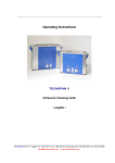
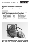
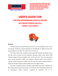
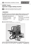
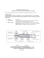
OPERATING INSTRUCTIONS
TECHSPAN Automatic wedge welding machine type common
Please read the operating instructions carefully before use and keep for further reference!
APPLICATION
The TECHSPAN common is an automatic hot wedge welding machine for overlap welding,
manufacturing of films and geomembrane liners in tunnels as well as in earthwork and civil
engineering.
•
•
Overlap
Type of seam
•
Type of wedge
V
r
max. 140mm
Welding seams are produced in accordance with DVS 2225 part I .
Other dimensions of seams are possible on request
In standard version, the TECHSPAN Common, is supplied with a
copper wedge for welding of PE and PP. On request we can supply a
ceramic wedge for welding all different kind of materials.
1
SECURITY WARNING
Danger! Unplug the tool before opening it as live components
and connections are exposed.
Danger of fire and explosion in case of incorrect use of the hot
wedge welder, especially near combustible materials and/or
explosive gases.
Danger of burns Do not touch the hot wedge when hot, allow the
tool to cool down.
Connect the tool to a socket outlet with protective earth conductor.
Any interruption of the protective earth conductor within or outside
the tool is dangerous!!! Use only extensions cables with a
protective earth conductor!
CAUTION
The voltage rating stated on the tool should correspond to the
mains voltage.
For personal protection, we strongly recommend to connect the tool
to an RCCB(Residual Current Circuit Breaker) before using it on
construction sites.
The tool must be operated under supervision.
Radiant heat from the hot wedge con ignite flammable materials.
Protect the tool from damp and wet.
TECHNICAL DATA
Voltage
Power consumption
Frequency
Temperature
Welding pressure
Drive
Size LxWxH
Weight
Tool with protection of class I
V~
W
Hz
°C
N
m/min.
mm
kg
230
2100
50/60
20 - 460
max. 1400
0.8 – 5.0
460 x 300 x 330
14
2
DESCRIPTION OF FUNCTIONS
•
Heating system → The wedge temperature is steplessly adjustable and electronically
controlled. According to the material thickness the hot wedge position can steplessly be
adjusted as required.
Cross-sectional diagram of hot wedge system
Pinch roller
Upper geomembrane liner
Upper drive /
pressure roller
Welding
direction
Adjustment screw
hot wedge
Hot wedge
Lower drive/
pressure roller
Lower geomembrane liner
Front guide roller
Rear guide roller
•
Welding pressure steplessly adjustable. The welding pressure is transmitted via a
toggle lever to the pressure rollers.
The equalisation of the pressure to both welded sections (L1 and L2) as well as on a
welded seam without test channel, is guaranteed by the swivel head.
This allows T-joints to be welded without problems. During the welding process the
pressure adjusts itself linearly to the change in material thickness of the geomembrane
liner.
Cross-sectional diagram of an overlap weld
L1
L2
S2
S2
LC
Reduction of seam thickness = S1 – S2
S1 : thickness of the upper and lower membrane
S2 : thickness of welded seam
L1 : welded section 1
L2 : welded section 2
LC : test channel
3
S1
•
Drive: double (upper and lower), steplessly adjustable and electronically controlled.
The control system is designed in such a way, that the adjusted speed remains constant
independently of the load.
WELDING PARAMETERS
Welding pressure: engage and position the welding tool onto the material to be welded.
Pull the toggle lever without engaging the hot wedge. By rotating the adjustment screw the
drive/pressure rollers will lightly touch the material to be welded, in this way you will define the
POINT ZERO(0) N of pressure. Unhook the toggle lever for the locking mechanism and open
the toggle lever.
Set the desired pressure by rotating the adjustment screw, to every single step of rotation you will
set 90N of pressure on seam. Lock than the desired pressure with the locking screw.
Warning: If the maximum welding pressure(1400 N) is exceeded, mechanicals damage may
occur.
Welding temperature: set the welding temperature with the UP – DOWN keys of the
temperature controller positioned on the left of the front panel. The switch ON-OFF of the
heating is positioned under this same controller. Start the welding only when the actual
temperature correspond to the set value. An alarm signal(AL) will be shown in the lower right
corner of the display if the actual temperature is too low than the set value, in this case the motor
can not be started or, if in function, will stop automatically.
Welding speed: set the welding speed by the potentiometer on the front panel, the motor is
switched on and off by the switch near the potentiometer. The speed shown on the display
corresponds to the actual welding speed.
4
WELDING
Welding preparation
-Laying of material
Width of overlap from 80 to 140 mm
Make sure that the surfaces of geomembrane liners, above and
below, are cleaned, as well as between the overlap.
-Mains supply
at least 3KW (generator) supplied with an RCCB
(Residual Current Circuit Breaker)
Operating conditions
Connect the tool to the mains
Start the tool with the main switch/level
Welding procedure
•
•
•
•
•
•
Ad just the welding parameters ( see page no. 4 )
Wait until the wedge has reached the adjusted temperature.
Guide and position the welding machine into the over-lapped geomembrane liner or film.
Switch on the drive motor with the foreseen switch.
Engage the hot wedge into the over-lapped geomembrane liner or film.
Push down the toggle lever to obtain the blockade.
Beginning of welding
• Check the welded seam(wash/seam thickness reduction). Eventually adjust the welding speed
by the foreseen potentiometer.
• Drive / adjust the direction of welding machine by the guide handle so that the minimum
overlap is reached.
•
End of welding
1cm before the end of the welded seam release the pressure lever, pull back the hot wedge and
switch off the motor with the foreseen switch.
5
ADJUSTING THE HOT WEDGE
The hot wedge can be adjusted depending to the material thickness.
• By cold wedge, engage the welding machine onto the geomembrane to be welded.
• Engage the wedge onto the geombembrane.
• Low the pressure lever after has adjusted the needed pressure.
• Remove the lower part of the chain housing.
• Loosen the hexagon cap screw which is inside the chain housing.
• Loosen the hexagon cap screw of the rear roller guide.
• Ad just the rear roller guide to the correct height. The distance between the rear roller
guide and the wedge should be the same as thickness of material to be welded.
• Tighten the hexagon cap screw of rear roller guide.
• Loosen the adjustment screw of wedge. The wedge equalizes automatically to the
thickness of material to be welded.
• Tighten the adjustment screw of the hot wedge.
• Ad just the front guide roller to the correct height. The distance between the inserted
material and the front guide roller should be approx. 1mm.
• Tigthen the hexagon cap screw in the chain housing keeping blocked the correspondent
screw of guide roller.
• Assemble chain guard lower part.
• Unhook the pressure lever and move the wedge from the welding position.
• Check that all the screws are well tight and proceed with a weld test.
MAINTENANCE
Clean the hot wedge with a wire brush at the end of working day
Clean the drive/pressure rollers with a wire brush
As required treat the chain with a suitable spray
After use, always check that the mains cable and plug are not damaged
SERVICE AND REPAIR
The welding machine should be checked by an authorised service centre approx. every 1000
hours of running time.
Inspections and repairs have to be executed exclusively by TECHSPAN authorised service centres.
GUARANTEE AND LIABILITY
For TECHSPAN guarantee and liability see our the general and sales conditions.
TECHSPAN rejects any guarantee claims for tools which are not in original condition.
Modifications of the tool will void any guarantee claims.
Technical data are subject to change without prior notice.
www.techspanonline.com