1
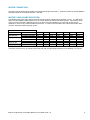
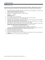
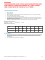
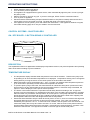
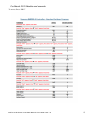
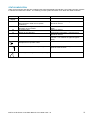
INSTALLATION AND OPERATING INSTRUCTIONS I INSTALLATION AND OPERATING INSTRUCTIONS HR Series II Hot Water Boilers & Pool Heaters INSTALLATION AND OPERATING INSTRUCTIONS Melbourne: 03 9554 2275 Sydney: 02 9853 2100 Brisbane: 07 3308 5400 10/06/2015 Gold Coast: 07 5552 2600 Townsville: 07 4750 3100 Adelaide: 08 8152 7600 Perth: 08 9350 2600 [email protected] www.hurlconheating.com.au INDEX 1.0 INTRODUCTION……………………………………………………………………………………….. 4 1.1 NOTICE TO INSTALLERS……………………………………………………………………………. 4 2.0 HR MODELS AVAILABLE…………………………………………………………………………….. 4 3.0 INSTALLATION………………………………………………………………………………………… 5 3.1 SAFETY RULES……………………………………………………………………………………….. 5 3.2 BOILER DIMENSIONS………………………………………………………………………………… 6 3.3 INDOOR INSTALLATION……………………………………………………………………………… 6 3.4 VENTILATION – AIR SUPPLY TO THE BOILER…………………………………………………… 7 3.5 CLEARANCES………………………………………………………………………………………….. 8 3.6 ELECTRICAL CONNECTION………………………………………………………………………… 8 3.7 GAS CONNECTION…………………………………………………………………………………… 8 3.8 WATER CONNECTION………………………………………………………………………………. 9 3.9 WATER FLOW & PUMP SELECTION……………………………………………………………… 9 4.0 COMMISSIONING…………………………………………………………………………………….. 10 4.1 STARTING BOILER………………………………………………………………………………….. 10 4.2 TESTING BURNER PRESSURE……………………………………………………………………. 10 4.3 FLOW SWITCH………………………………………………………………………………………… 10 5.0 OPERATING INSTRUCTIONS………………………………………………………………………. 11 5.1 CONTROL SYSTEMS - ON/OFF BOILERS………………………………………………………... 11 5.2 CONTROL SYSTEMS – MODULATING BOILERS……………………………………………….. 14 5.3 CONTROL SYSTEMS – POOL & SPA HEATERS………………………………………………… 17 5.4 INDICATORS…………………………………………………………………………………………… 19 5.5 ALARM………………………………………………………………………………………………….. 19 5.6 MAIN PCB………………………………………………………………………………………………. 20 6.0 GAS CONVERSION…………………………………………………………………………………… 21 7.0 MAINTENANCE………………………………………………………………………………………… 21 8.0 TROUBLESHOOTING…………………………………………………………………………………. 22 9.0 ONE YEAR LIMITED WARRANTY…………………………………………………………………… 23 INST 219 HR Series II Hot Water Boiler & Pool Heater V06 – 15 2 INTRODUCTION Congratulations on your purchase of a Hurlcon HR Series II Hot Water Boiler. Correct installation and service of your new heating system and correct chemical maintenance of the water will ensure years of service. The HR Series Boiler is a compact lightweight and efficient gas fired hot water boiler. It is equipped with features that take advantage of new technology developed exclusively by Hurlcon. The Hurlcon Boiler is a floor mounted atmospheric boiler with a built in balanced flue for outdoor installation or integral draught diverter for flued installations. The power output is controlled by an integrated electronic controller to maintain the set point water temperature over a wide load range. The electronic display tells at a glance the operational status of the boiler. Note: The appliance is not intended for use by young children or infirm person without supervision. Please ensure that young children are supervised to ensure that they do not play with the appliance. NOTICE TO INSTALLERS This is a Floor Mounted - Hot Water Boiler For use with Natural Gas or Propane Gas as per the attached data label. The information below is given to assist the installer with the installation of this range of HR 600-1800 Boilers. Please read it carefully in order to make the installation as easy as possible and to ensure the system works well and conforms to the necessary government regulations. PLEASE READ THESE INSTRUCTIONS BEFORE STARTING THE INSTALLATION. It is important that this boiler is installed and serviced as detailed in these instructions person. This boiler is to be installed and serviced to the requirements of the Local Building, Gas, Water and Electricity Authorities. These instructions are to be held by the owner / user after installation. by an AUTHORISED This appliance must be installed in accordance with the installation instructions, local gas fitting regulations, the AGA Installation Code AG 601 and any other relevant statutory authorities. Refer to data plate for details of gas type, gas consumption and burner pressure. HR MODELS AVAILABLE Model Input MJ (NG) Output kW 600 594 136 800 792 180 1000 990 225 1200 1188 270 1400 1386 316 1600 1584 361 1800 1782 406 Hurlcon HR Boilers are available in 7 models and 3 control types, Modulating, On / Off and Pool Heater. Each model is covered in this booklet. INSTALLATION INST 219 HR Series II Hot Water Boiler & Pool Heater V06 – 15 3 THIS APPLIANCE MUST BE INSTALLED BY AN AUTHORISED PERSON. Check that the boiler is the correct type and model for the installation and that there is no damage. Contact your representative or nearest Hurlcon office if there are any queries. Refer to boiler data plate for specifications of gas type, gas consumption, burner pressure and water pressure. This appliance must be installed in accordance with local regulations, A.G.A. Installation Code AG 601, AS5601 and relevant electrical standards. The boiler should be installed after the pump. The water connections are located on the right hand side of the boiler. Left hand connection models are available by special order. The inlet and outlet are clearly marked. Water connections are 1 ½” or 2”mm BSP FI. The Hurlcon Boiler is fitted with a built in flow switch and will not start unless full of water and the pump is operating. The Hurlcon Boiler incorporates a balanced flue terminal and is suitable for outdoor installation. Internal models have an integral draught diverter and spigot for flue termination. Boiler clearances are detailed in Section 3.5 SAFETY RULES For your safety – read before lighting This appliance is equipped with an ignition device, which automatically lights the pilot. Do not try to light the pilot by hand. BEFORE OPERATING smell all around the appliance area for gas. Be sure to smell next to the floor because some gasses are heavier than air and will settle on the floor. Safety WHAT TO DO IF YOU SMELL GAS Do not try to light any gas appliance. Do not touch any electrical switch. Turn off the gas supply at the gas meter. Immediately call your gas supplier or licensed gas fitter. NOTE. Some gases are heavier than air and it may be necessary to check for gas at floor level. House keeping Do not store or use flammable liquids or chemicals near this appliance. Do not use aerosols in the vicinity of this gas appliance. Keep this appliance free of debris. WARNING: Should overheating occur or the gas supply fail to shut off, turn off the manual gas control valve to the appliance. Do not use this boiler if any part has been under water. INST 219 HR Series II Hot Water Boiler & Pool Heater V06 – 15 4 BOILER DIMENSIONS *Indoor model shown, outdoor model supplied without flue spigot. INDOOR INSTALLATION If the HR Boiler is to be installed indoors the correct size flue must be connected. The HR series boilers have an inbuilt draught diverter so the flue can be connected directly to the outlet spigot. The top of the boiler is not designed to support the flue. Suitable support must be used. Boiler model HR 600 HR 800 HR 1000 HR 1200 HR 1400 HR 1600 HR 1800 Flue size 255 mm 305 mm 405 mm 405 mm 455 mm 455 mm 455 mm The flue must also be terminated with an approved gas flue cowl (not a Chinaman’s hat) 600mm above any roofline that is within 1.5 metres horizontally from the flue. INST 219 HR Series II Hot Water Boiler & Pool Heater V06 – 15 5 VENTILATION – AIR SUPPLY TO THE BOILER When installing the boiler indoors, it is imperative that an adequate supply of fresh air is provided for combustion. Failure to provide adequate ventilation voids all warranties and may be a danger to persons or property. Please refer to AS5601 / AG 601 for full details. Two permanent openings shall be provided directly to outside. The openings shall be located to ensure the distance between the top of the upper opening and the ceiling of the room or enclosure, and the distance between the bottom of the lower opening and the floor of the room or enclosure does not exceed 5% of the height of the room or enclosure. The minimum vertical dimension of any free ventilation opening shall be 6 mm. The minimum free ventilation area provided by each opening shall be: MODEL HR AREA m2 600 800 1000 1200 1400 1800 1800 0.09 0.12 0.15 0.18 0.21 0.24 0.27 The minimum free area provided by each vent can also be calculated by using the following formula, unless otherwise stated in AG 601. A =0.00015 x T Where A = Minimum free ventilation area (m 2) T = Total hourly input of all appliances (MJ/h) The following diagram is provided as a guide only. All flueing and installation work must be carried out by an authorized person. Flueing must conform to local regulations and to A.G.A. installation code AG 601. Care must be taken to provide the correct ventilation and correct flueing materials in close proximity to combustible surfaces. 1500 600 Approved gas termination cowl Upper grille for fresh air ventilation Lower grille for fresh air ventilation INST 219 HR Series II Hot Water Boiler & Pool Heater V06 – 15 6 Do not install spa blowers in the same room as a gas boiler. This is potentially dangerous to spa users. Do not store chemicals or fuel in the same room as the gas boiler. This may cause fire or explosion. Installations, which obtain air from a source other than directly from outside, must comply with AS 5601/AG601. Warning: Air supply to the boiler room must not be affected by mechanical exhaust vents located in other parts of the building, such as kitchen or bathroom fans, spa blowers, etc. Mechanical exhaust vents may create a negative pressure in the boiler room that can become a hazard by asphyxiation, explosion or fire. CLEARANCES Clearances from non combustible surfaces are: Recommended 1000 mm 500 mm 500 mm 1500 mm 500 mm minimum Front Both sides Rear Above Combustible surfaces Minimum 1000 mm 200 mm 200 mm 1500 mm 500 mm minimum The boiler must be installed at least 500 mm from any combustible surface. Clearances must comply with AG 601 and any local requirements. Recommended clearances are suggested for easier component removal, connections and servicing. The boiler is fitted with a plinth however this must be installed on a fireproof base. Boiler must be installed on a platform / base with a fully enclosed floor area, equal or greater than the boiler size. ELECTRICAL CONNECTION The boiler is supplied with a 3 pin plug top for connection to a 240V 10 amp supply. The boiler incorporates a 240/24 VAC transformer which supplies power to the control circuit. A 24VAC 1 AMP supply is provided on the PCB for powering external devices. All equipment connected to mains power should be protected by an RCD circuit breaker. The boiler has a 1Ø 240 vac 8 amp power supply for the pump electrical connection which incorporates the pump run on timer. For bigger loads or 3Ø pumps a contactor must be fitted. 24 volt connections are provided for a remote start circuit with dry contact and run and fault contacts. These are dry contacts rated at 24 vac only. There is also provision for remote alarm reset and outdoor ambient sensor (modulating models). GAS CONNECTION The gas connection is on the left side of the boiler. Check that the boiler you have been supplied is suitable for the type of installation and the gas that is available. The gas supply pressure must be between the minimum and maximum as shown on the boiler data plate. The gas connection size will be dependant on boiler model and gas type. For Natural gas appliances a regulator set to 1.13 kPa is recommended prior to the boiler. Natural pressure gas Propane pressure gas min inlet test point max inlet min inlet test point max inlet 1.1 kPa 0.85 kPa max 5 kPa 2.75 kPa 2.70 kPa max 5 kPa all models all models all models all models all models all models INST 219 HR Series II Hot Water Boiler & Pool Heater V06 – 15 7 WATER CONNECTION The boiler comes fitted with removable screwed bronze flange connections. These are 40mm for models HR600 – HR1000 and 50mm for models HR1200 – HR1800. WATER FLOW & PUMP SELECTION The following flow rates and pressure drops should be used as a guide when selecting a pump. The HR series boiler has an integrated pump start and run on circuit capable of switching 240VAC 8 Amp. If the built in pump control circuit is not used a separate pump run on timer must be installed to run the pump on after burner shutdown to remove any residual heat from the boiler. It is also recommended in this case that the boiler start circuit be interlocked with the pump control. FLOW RATES & PRESSURE DROPS Boiler Model 10 Deg C Rise max flow rate 15 Deg C Rise 20 Deg C Rise min flow rate Litres per sec Pressure drop kPa Litres per sec Pressure drop kPa Litres per sec Pressure drop kPa 600 800 1000 1200 1400 1600 1800 3.44 8.0 2.29 3.9 1.72 2.8 4.56 13.0 3.04 7.6 2.28 4.7 5.71 17.0 3.81 10.5 2.86 7.8 6.86 24.0 4.57 13.5 3.43 8.8 8.00 29.0 5.34 18.0 4.0 9.2 9.15 35.0 6.10 24.0 4.58 11.0 10.3 36.0 6.87 26.0 5.15 12.0 The boiler must be set up to operate with a flow rate and corresponding temperature rise between 10° and 20°. INST 219 HR Series II Hot Water Boiler & Pool Heater V06 – 15 8 COMMISSIONING STARTING BOILER Ensure that all relevant documents and necessary approvals have been obtained. Make sure that the area around the boiler is clean and free of flammable materials, debris, liquids and chemicals. Ensure that the plant room ventilation is installed and free of obstruction. Check that the system is full of water and any air has been bled. 1. 2. 3. 4. 5. 6. 7. 8. 9. 10. 11. 12. 13. 14. Has the flow switch and or pressure switch fitted to the boiler been set and adjusted. The boiler will not light if the flow/pressure switch does not make. Visually check wires and fittings, and gas valve train. Check minimum* inlet supply gas pressure – adjust if required. Nat Gas 1.15 kPa Propane Gas 2.75 kPa *Dynamic pressure Turn off isolation valves to main gas train. Turn on isolation valves to pilot only. Check for leaks with soapy water along gas train. Start heater, allow pilot only to light. - Turn heater off when lit. Create a vacuum in your manometer and connect to test point on outlet of main gas valve, check negative pressure is stable. Burner isolation valve must be closed. Start heater - allow pilot to light. Check the main valve does not open when the pilot is lighting. Manometer pressure will change if wired incorrectly and main valve opens. Upon satisfactory results, with pilot going, open main gas train isolation valve approx 1/4 and allow burners to light. Should they fail to light, close valve and identify fault. Likely cause a) Minimum gas pressure is set too low (modulating models). b) Gas valves did not get power and did not open. c) Main burner test switch in off position. (located on main PC Board) On models 1200 – 1800 fitted with dual flame sense a flame fail may occur if the burners do not cross light within the allowable time. Reset the boiler and wait for the boiler to relight. Upon finding cause of fault restart at step 8 Upon burners lighting open isolation valve fully. Leak test the complete gas valve train assembly. Adjust the water temperature setpoint at the temperature controller until the correct set temperature is displayed. Turn boiler off then on. Check that the boiler lights automatically. INST 219 HR Series II Hot Water Boiler & Pool Heater V06 – 15 9 WARNING THESE BOILERS HAVE A HIGH GAS CONSUMPTION AND CAN CREATE LARGE EXPLOSIONS IN A VERY SHORT TIME. CARE MUST BE TAKEN AT ALL TIMES TESTING BURNER PRESSURE Set up manometer Turn boiler “OFF”. Remove screw from ⅛” brass test point located on outlet side of gas valve or on the burner manifold Connect manometer tube to test point. Turn boiler “ON” and wait for main burner to ignite. Once main burner has ignited, the manometer must indicate the nominal burner pressure listed below. (Modulating burners must be at full fire) If a separate regulator is fitted adjust as required. Some gas valves have a built in regulator that can be adjusted. See the datasheet section for correct adjustment for the type of gas valve fitted. Maximum inlet gas pressure is: Natural Gas 5.0 kPa Propane Gas 5.0 kPa Maximum burner pressure is: Model HR 600 HR 800 HR 1000 HR 1200 HR 1400 HR 1600 HR 1800 Natural Gas kPa 0.85 0.85 0.85 0.85 0.85 0.85 0.85 Propane Gas kPa 2.70 2.70 2.70 2.70 2.70 2.70 2.70 FLOW SWITCH The Hurlcon HR Boiler has a factory fitted flow switch (pressure switch on Pool Heater models) located in the outlet manifold which allows the burner to operate only when the system is full of water and the circulating pump is operating. The flow switch paddle / pressure switch sensitivity should be set during commissioning. Air in the system may stop the boiler from lighting. INST 219 HR Series II Hot Water Boiler & Pool Heater V06 – 15 10 OPERATING INSTRUCTIONS STOP! Read the safety rules above. Turn off electric power to appliance. This appliance is equipped with an ignition device, which automatically lights the pilot. Do not try to light the pilot by hand. Wait five minutes to clear out any gas. If you then smell gas, STOP! Refer to instructions above. Turn on power to appliance. Set thermostat to desired setting and press ON/OFF switch to ON (Genus models) and ensure that if a remote start circuit is connected it is made. The boiler will ignite in around 30 seconds If the appliance will not operate, press and release the reset switch. If the appliance still does not ignite, see trouble shooting page 22 or call your installer / service technician. CONTROL SYSTEMS - ON/OFF BOILERS ON / OFF BOILER - 3 BUTTON GENUS IV CONTROLLER ON/OFF WARM < ○ > HURLCON COOL HURLCON DESCRIPTION The sophisticated Genus IV digital thermostat displays temperature read out, set point temperature and operating status of the boiler including any fault conditions. TEMPERATURE DISPLAY The temperature display indicates water temperature in the inlet of the boiler. Therefore the pump must be operating for an accurate water temperature to be displayed. Temperature sensing can be changed to leaving water by moving the sensor to the vacant pocket in the flow side of the header. Water temperature can be set between 55˚C - 90˚C. To select your desired water temperature press the up or down button repeatedly until the desired set temperature is reached. To prevent rapid cycling of the boiler, the thermostat has an inbuilt time delay which prevents the boiler from turning on for two minutes after the set point has been reached. If the time delay is activated, the symbol “L” will be displayed. This is part of normal operation. The Genus control thermostat also incorporates several safety features including a 100˚ C high limit function to prevent overheating. On simultaneous shut down of the circulating pump and boiler, the water within the boiler may exceed the set temperature for a short period. If the pump and boiler are restarted during this period, the thermostat will go into a standby mode and prevent the boiler from relighting until the temperature within the boiler has dropped below the set temperature. Should the thermostat fail to stop the boiler at the set point or at 100˚ C, there is a manual reset high limit thermostat designed to lock the boiler out and prevent further heating. Plus a lock out condition is indicated by the symbols F1 or F2. To reset a lock out condition, turn the power off for five seconds. The mechanical safety device may also need to be reset. To do this, raise the front access panel locate the high limit safety thermostat and press the red button. If the boiler has cooled sufficiently, a positive “click” should be heard and felt. The high limit is located on the front right of the electrical panel. INST 219 HR Series II Hot Water Boiler & Pool Heater V06 – 15 11 GENUS IV 3 BUTTON CONTROLLER Switching differential. The temperature switching differential can be adjusted to stop short cycling. See table below for appropriate codes. (Default 5°.) °F or °C. The display can be toggled between Celsius and Fahrenheit. See table below for codes. (Default °C.) With the unit switched off, press and hold the on/off button then press the following. Degrees C Degrees F Button presses 1 2 U D U D 5 ° differential 10 ° differential 15 ° differential 20 ° differential D D D D D D D U U = warm button 3 D D 4 D U D U U D D = cool button U D U D 55 – 90 DEGREE SETTING The Genus IV controller has the facility to limit the maximum setpoint. The factory default maximum is 90°. For 55° maximum setpoint contact your Hurlcon representative. INST 219 HR Series II Hot Water Boiler & Pool Heater V06 – 15 12 STATUS INDICATION Under normal running and also fault conditions the thermostat LCD will display a set of alpha numeric symbols to indicate the status of the boiler. The meaning of each symbol and action to be taken are listed as follows: SYMBOL Temp Display F0 MEANING Unit has power. ACTION No action If water temperature reads greater than 0C, phone for service. F3 F4 Boiler locked off, thermistor wire is disconnected or water at 0C (freeze conditions). Thermostat reads greater than 100C or thermistor short circuited. Thermistor fault Flame roll out detected L Boiler locked out on time delay F1 Pump operating & sufficient water flow to operate boiler Allow water to cool, turn boiler off then on again Phone for service Press boiler reset switch. If fault reoccurs phone for service. No action. Boiler in limit start delay for 2 minutes. Turn off then on again to bypass delay. No action Thermostat calling for heat operating. No action, boiler electronic Ignition should ignite in a few seconds Burner system has ignited and is operating. No action INST 219 HR Series II Hot Water Boiler & Pool Heater V06 – 15 13 CONTROL SYSTEMS – MODULATING BOILERS MODULATING BOILER - SIEMENS RWF40 CONTROLLER Flow Temp. Manual operation Control system ready Set Point Temp Modulating valve closing Modulating valve opening Not used 6 6 Limit Comparator Increase value button Decrease value button PGM PGM Program set button EXIT EXIT Program exit button WRF 40 DESCRIPTION The sophisticated digital thermostat controller provides display of water flow temperature, set point temperature and operating status of the boiler. Adjusting the controller settings correctly will result in accurate control of the modulating function of the boiler. TEMPERATURE DISPLAY The RED upper display indicates the flow water temperature from the boiler. The lower GREEN display indicates the boiler water flow set temperature. The controller is set to Hurlcon factory default settings at the time of manufacture. These settings are suitable for a wide range of applications but may require fine tuning depending on individual project specifications and characteristics. A detailed Siemens RWF 40 product manual is available from Siemens or contact Hurlcon. This details all parameters and settings. An auto tune function is available for automatic tuning of the PID settings. When the heater is called to run the amber indicator will illuminate. The indicators may also flash indicating that the controller is increasing or decreasing the modulating valve output in accordance with its calculations. This can occur whether the burner is operating or not. The controller can be put into manual operation by pressing the EXIT button for 5 seconds. The Symbol will illuminate. Pressing the buttons will adjust the modulating valve position. Press EXIT for 5 seconds to restore auto operation. To adjust the main setpoint (SP1) press the PGM button once. Use the buttons to set the desired value and press PGM to accept. Press EXIT to exit or wait until the display returns to the set value. INST 219 HR Series II Hot Water Boiler & Pool Heater V06 – 15 14 For March 2015 Models and onwards To access Press “PRG” INST 219 HR Series II Hot Water Boiler & Pool Heater V06 – 15 15 Pre March 2015 models Siemens RWF40 controller program standard settings To access press PRG Process data. Display Parameter Setpoint 1 * Setpoint 2 (optional) * Digital Setpoint Shift (optional) * SP1 SP2 Dsp Outside Temperature (optional) tA Predefinition of external setpoint * To access press and hold PRG for 10 seconds Factory Setting 80 0 0 SPE Parameter Level. Parameter Limit value of limit comparator * Switching differential for limit comparator * Proportional band * Derivative time Integral action time Contact spacing * Actuator running time Switch-on threshold burner / stage II * Switch-off threshold stage II * Upper switch-off threshold * Response threshold Heating curve slope Parallel displacement * To access press and hold PRG for 10 seconds Actual Settings Display Factory Setting AL HySt Pb.1 dt rt db tt HyS1 HyS2 HyS3 q H P 20 0 20 30 120 2 40 -5 0 5 0 4 0 Configuration Level. Parameter Analog input 1, 2 & 3 setpoint changeover / shift Limit comparator: controller type: setpoint 1 locking Unit address decimal place / unit, signal for out-ofrange Measurement range start analog input 1 * Measurement range end analog input 1 * Measurement range start analog input 2 * Measurement range end analog input 2 * Lower setpoint limit * Upper setpoint limit * Actual value correction, analog input 1 * Actual value correction, analog input 2 * Actual value correction, analog input 3 * Filter time constant for digital filter, analog input 1 Display Factory Setting C111 C112 9030 0010 C113 SCL SCH SCL2 SCH2 SPL SPH OFF1 OFF2 OFF3 DF1 0100 0 100 0 0 50 80 0 0 0 1 For OUTDOOR AMBIENT TEMP control refer to wiring diagram. For NIGHT SETBACK connect D2 and Ground on RWF40 to a time clock or similar dry contact. INST 219 HR Series II Hot Water Boiler & Pool Heater V06 – 15 16 CONTROL SYSTEMS – POOL & SPA HEATERS POOL & SPA HEATER - 4 BUTTON GENUS IV CONTROLLER POOL/SPA < ○I ON/OFF > HURLCON WARM COOL HURLCON DESCRIPTION The sophisticated Genus IV digital thermostat displays temperature read out, set point temperature and operating status of the boiler including any fault conditions. TEMPERATURE DISPLAY The temperature display indicates water temperature in the inlet of the heater. Therefore the pump must be operating for an accurate pool or spa water temperature to be displayed. Comfortable pool temperature is between 26˚C and 30˚C. To select your desired temperature press the up or down button repeatedly until the desired temperature is reached. To prevent rapid cycling of the heater, the thermostat has an inbuilt time delay which prevents the heater from turning on for two minutes after the set point has been reached. If the time delay is activated, the symbol “L” will be displayed. This is part of normal operation. The thermostat can be set to temperatures between 10˚C and 40˚C. On simultaneous shut down of the circulating pump and heater, the water within the heater may exceed 45˚C for a short period. If the pump and heater are restarted during this period, the thermostat will go into a standby mode and prevent the heater from relighting until the temperature within the heater has dropped below the set temperature. Should the thermostat fail to stop the heater at the set point or at 40˚C, there are three temperature limiting safety devices designed to lock the heater out and prevent further heating. A lock out condition is indicated by the symbols F1 or F2. To reset a lock out condition, turn the power off for five seconds. For an F2 fault it may be necessary to reset the high limit thermostat. The high limit is located behind the front access panel on the front of the electrical panel to the right.. INST 219 HR Series II Hot Water Boiler & Pool Heater V06 – 15 17 STATUS INDICATION Under normal running and also fault conditions the thermostat display will indicate a set of alpha numeric symbols to indicate the status of the boiler. The meaning of each symbol and action to be taken are listed as follows: SYMBOL Temp Display F0 MEANING Unit has power. ACTION No action If water temperature reads greater than 0C, phone for service. F3 Boiler locked off, thermistor wire is disconnected or water at 0C (freeze conditions). Thermostat reads greater than 100C or thermistor short circuited. Thermistor fault F4 Flame roll out detected Press boiler reset switch. If fault reoccurs phone for service. No action. Boiler in limit start delay for 2 minutes. Turn off then on again to bypass delay. No action F1 L Heater locked out on time delay Pump operating & sufficient water flow/pressure to operate heater Allow water to cool, turn boiler off then on again Phone for service Thermostat calling for heat operating. No action, boiler electronic Ignition should ignite in a few seconds Burner system has ignited and is operating. No action INST 219 HR Series II Hot Water Boiler & Pool Heater V06 – 15 18 INDICATORS As well as the individual temperature controls all Hurlcon HR models have a series of LED indicators on the front panel. Green LED indicators for Power External call Water flow / pressure Burner lit Red LED indicators for High limit fault Flame fail fault Flame roll out fault Alarm mute and fault reset buttons are located below the led indicators. A high limit fault will also require the high limit safety thermostat to be reset located on the front of the main electrical panel. For diagnostics during service LED’s on the main PCB indicate high limit, flow, pressure, remote start and pump status all visible with the front panel elevated and electrical cover removed. ALARM The HR heater has a built in alarm. The onboard piezo alarm can be enabled / disabled with the jumper located on the main PCB. The alarm mute is on the front panel. INST 219 HR Series II Hot Water Boiler & Pool Heater V06 – 15 19 MAIN PCB F1 F2 F3 F4 F5 MAINS FUSE 10 AMP SLOW BLOW 240VAC. MAINS FUSE 1 AMP 24VAC. LGB CONTROLLER FUSE 2 AMP 240VAC PUMP FUSE 8 AMP SLOW BLOW 240VAC USER OUTPUT 1 AMP 24VAC INST 219 HR Series II Hot Water Boiler & Pool Heater V06 – 15 20 GAS CONVERSION Ensure that the valve train will pass the required gas volume. Turn off gas supply to unit. Turn off power supply to pump and boiler. Remove front access panel Disconnect gas supply from gas valve. Loosen the bolt at each end of the manifold tube securing burner assembly to the combustion chamber. Disconnect wiring from gas valves and slide complete burner tray out through the access opening. Remove burner injectors and replace with desired gas type injectors. Remove pilot burner and change pilot injector to desired gas type. Refer to the gas valve instructions in data sheet section to change the spring range. Re-install burner assembly and reconnect gas supply. Check gas system for leaks. Commence lighting procedure as described above. Adjust burner pressure as described in the commissioning section. MAINTENANCE All service, maintenance and commissioning of these appliances should be carried out by suitably qualified and licensed personnel. Routine maintenance can extend the life of the appliance. Hurlcon recommends regular routine maintenance performed at least annually. Equipment installed in harsh environments or with extreme workloads may require maintenance more often. Annual service procedure. Isolate services as required. Clear and remove any dust and debris or inappropriate material from around the appliance and its immediate area. Remove access covers and inspect for debris, clean as required. Isolate and disconnect the gas train and electrical connections to facilitate burner tray removal. Remove the burner tray. Clean main burner injectors and burners as required. Dismantle and clean pilot assemblies, including injectors. Clean and re-align flame rods. Inspect the combustion chamber. Inspect the heat exchanger for signs of damage and blockage, clean tube fins if required. Inspect tube/header connection point for signs of water leakage. Manually operate pressure relief valve to check that the drain is clear and the valve reseats. Refit burner tray and reconnect gas train and electrical connections. Leak test the gas train. Replace all access covers Check all air vents and louvres, clean as required. Restore services as required. Recommission unit, check settings and prove the operation of all safety devices. Check and monitor the operation of the appliance through several cycles or for as long as is practical. Ensure temperature controller settings are returned to normal. INST 219 HR Series II Hot Water Boiler & Pool Heater V06 – 15 21 TROUBLESHOOTING Access to the electrical panel should be by suitably qualified personnel only, however these basic chcks may help if the boiler is not running or if the boiler will not light: Is the 240 volt power supply on and is the power indicator and temperature controller on? Check the supply and or mains fuse on PCB. Is the temperature controller turned on and the actual water temp below setpoint? Turn on controller and raise setpoint. Is the high limit safety tripped? Reset button located on the front of the electrical panel. Has the unit flame failed? Press the reset button on the front panel. Check the gas supply is on and available. Has the unit had a flame roll out? Check the area around the roll out sensor for damage and press the reset button on the front panel. Is the external heating call made? Check time clock, remote thermostat or BMS system as required. Is the flow indicator on? Check that pump is running and flow switch / pressure switch is made. Is the 24 volt control fuse ok? Check F2 Does the boiler begin ignition? Check for parasitic flame. Check that the LGB controller indicator is rotating and F3 is ok. Is the pilot lighting? Check pilot solenoid opens, the ignition module has power and the ignitor sparks. If the boiler cannot be made to perform correctly, please contact Hurlcon Service on freecall 1300 727 116 or your installer / service contractor. INST 219 HR Series II Hot Water Boiler & Pool Heater V06 – 15 22 ONE YEAR LIMITED WARRANTY GENERAL CONDITIONS Hurlcon cover your boiler with a limited 1 year warranty against defective materials and workmanship from the date of purchase (plus 30 days to allow for installation). The heat exchanger, including headers are covered by a five year warranty (plus 30 days to allow for installation). Proof of purchase date must be provided in order to substantiate warranty claim. The warranty does not include in field labour costs unless purchased separately. Any costs for transport of faulty or replacement parts, removal or reinstallation are the owner’s responsibility. Hurlcon assumes no liability for consequential damages of any kind. Periodic maintenance of your boiler is recommended, see page 20. LIMITATIONS All warranties only apply if the boiler is installed and operated in complete compliance with the installation and operating instructions. The warranty shall not apply to any boilers or parts that have been subject to accident, negligence, alteration, abuse or misuse. ADDITIONAL WARRANTY EXCLUSIONS: This warranty does not cover failures or malfunctions resulting from: Failure to properly install, operate or maintain the boiler in accordance with our printed instructions provided. Abuse, alteration, accident, fire, flood and the like. Examples of misuse or neglect include, but are not limited to, physical damage from external force, not following installation instructions, leaving door off for extended periods of time, inappropriate application of the boiler, etc. Scaling, freezing, or other conditions causing an inadequate water circulation. Incorrect gas pressure or gas supply. Incorrect or excessive flow rate of water. Failing to correctly bleed the water system of air. Chemical contamination of combustion air or use of chemical additives to the water. No person is authorised to make any warranties on Hurlcon’s behalf. To place a service call, contact Hurlcon Service on freecall 1300 727 116. INST 219 HR Series II Hot Water Boiler & Pool Heater V06 – 15 23 INSTALLATION AND OPERATING INSTRUCTIONS I INSTALLATION AND OPERATING INSTRUCTIONS HURLCON HEATING Pty. Limited. A.B.N. 97 007 284 504 www.hurlconheating.com.au email: [email protected] Information and specifications subject to change without notice. Victoria: Ph: (03) 9554 2275 Fax: (03) 9554 2272 New South Wales: Ph: (02) 9853 2100 Fax: (02) 98532170 Queensland: Ph: (07) 3308 5400 Fax: (07) 3308 5470 South Australia: Ph: (08) 8152 7600 Fax: (08) 8152 7670 INST 219 HR Series II Hot Water Boiler & Pool Heater V06 – 15 Western Australia: Ph: (08) 9350 2600 Fax: (08) 9350 2670 Gold Coast: Ph: (07) 5552 2600 Fax: (07) 5552 2670 Townsville: Ph: (07) 4750 3100 Fax: (07) 4750 3170 24