1
Installation Manual
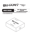
B-500-RX-230-IR
HDBaseT Matrix Receiver
B-500-RX-230-IR Installation Manual
Important Safety Instructions
WARNING: To reduce the risk of fire or electric shock, do not expose this apparatus to rain or
moisture. Do not remove cover. No user serviceable parts inside. Refer servicing to qualified
service personnel.
1.
Read and follow all instructions and warnings in this manual. Keep for future reference.
2.
Do not use this apparatus near water.
3.
Clean only with a dry cloth.
4.
Do not block any ventilation openings. Install according to manufacturer’s instructions.
5.Do not install near any heat sources such as radiators, heat registers, stoves or other apparatus
(including amplifiers) that produce heat.
6.Do not override the safety purpose of the polarized or grounding-type plug. A polarized plug has
two blades - one wider than the other. A grounding type plug has two blades and a third grounding
prong. The wide blade or the third prong is provided for your safety. If the provided plug does not fit
into your outlet, consult an electrician for replacement of the obsolete outlet.
7.Protect the power cord from being walked on or pinched particularly at plug, convenience
receptacles, and the point where it exits from the apparatus.
8.
Only use attachments/accessories specified by the manufacturer.
9.Refer all servicing to qualified service personnel. Servicing is required when the apparatus has
been damaged in any way, such as when the power-supply cord or plug is damaged, liquid has
been spilled or objects have fallen into the apparatus, the apparatus has been exposed to rain or
moisture, does not operate normally, or has been dropped.
10.DO NOT EXPOSE THIS EQUIPMENT TO DRIPPING OR SPLASHING AND ENSURE THAT NO
OBJECTS FILLED WITH LIQUIDS, SUCH AS VASES, ARE PLACED ON THE EQUIPMENT.
11.TO COMPLETELY DISCONNECT THIS EQUIPMENT FROM THE AC MAINS, DISCONNECT THE
POWER SUPPLY CORD PLUG FROM THE AC RECEPTACLE.
12. THE MAINS PLUG OF THE POWER SUPPLY CORD SHALL REMAIN READILY OPERABLE.
CAUTION
CAUTION: TO REDUCE THE RISK OF
ELECTRICAL SHOCK.
The lightning flash with arrowhead symbol, within an equilateral
triangle, is intended to alert the user to the presence of un-insulated
dangerous voltage within the product’s enclosure that may be of
sufficient magnitude to constitute a risk of electric shock to persons.
DO NOT REMOVE COVER. NO USER
SERVICEABLE PARTS INSIDE.
The exclamation point within an equivalent triangle is intended to alert
REFER SERVICING TO QUALIFIED
SERVICE PERSONNEL.
(servicing) instructions in the literature accompanying the appliance.
the user to the presence of important operating and maintenance
pg.2
© 2013 Binary
B-500-RX-230-IR Installation Manual
1. Table of Contents
2. Product Overview...................................................................................................4
2.1. Features............................................................................................................4
2.2. Package Contents.............................................................................................4
3. Recommended for Installation..............................................................................4
4. Receiver Layout.....................................................................................................5
5. Wiring Recommendations.....................................................................................6
5.1. HDBaseT Link....................................................................................................6
5.2. HDMI Cable.......................................................................................................7
6. Power Supply.........................................................................................................7
7. Installation Instructions.........................................................................................8
8. IR Pass-Through.....................................................................................................9
8.1. Port Pinouts.......................................................................................................9
8.1.1. IR Receiver Port (3.5mm {1/8”} Stereo)......................................................9
8.1.2. Yellow Tag IR Adapter.................................................................................9
8.1.3. IR Flasher Port............................................................................................9
8.2. IR Installation....................................................................................................10
8.3. IR Pass-Through Application Diagrams............................................................10
8.3.1. IR Control System to Control Displays.......................................................10
8.3.2. IR Receiver System to Control Sources....................................................10
9. Specifications........................................................................................................11
10. WARRANTY..........................................................................................Back Cover
11. Contacting Technical Support............................................................Back Cover
pg.3
www.snapav.com Support: 866.838.5052
B-500-RX-230-IR Installation Manual
2. Product Overview
The B-500-RX-230-IR extends HDMI over a single Cat5e/6 using HDBaseT technology allowing
video and audio transmission to remote displays from any HDBaseT Transmitter including the B-500MTRX-230 family of HDBaseT matrix switchers. The B-500-RX-230-IR supports all HDMI defined
Audio and Video formats, including 3D Video and 4K, and features bi-directional IR pass-through.
2.1. Features
Form and Function
•Designed specifically for use with B-500-MTRX-230 HDBaseT matrix switchers to extend HDBaseT
to displays without the need for a separate transmitter
• Wall-mountable housing design for easy installation
• Extends HDMI formats over a single cable
Cat5e/Cat6:
Up to 200ft (4k up to 115 ft)
Cat6a:
Up to 230ft (4k up to 130 ft)
• Transmits HDMI Signal via HDBaseT up to 10.2Gbps
• HDCP 1.4 Compliant
• Latch locking power supply
Video
• 2D Resolutions up to 1080p@60Hz – 48 Bit Deep Color
• 3D Resolutions up to 1080p@24Hz – 48 Bit Deep Color
• 4K x 2K up to 130 ft.
Audio
• Supports all HDMI supported audio formats, including DTS-HD Master and Dolby TrueHD
Bi-Directional IR Pass-Through
• Supports IR Signal up to 60 KHz
• Adaptive Circuit on IR Receiver accepts input levels from 2V DC to 12V DC.
2.2. Package Contents
(1) B-500-RX-230-IR
(1) 5V DC 2A Power Supply
(1) Yellow Tag Adapter
(2) Mounting Screws
(4) Rubber Feet
(1) Installation Manual
(2) HDBaseT Cable Labels
3. Recommended For Installation
Note: For use in applications utilizing a B-500-MTRX-230 matrix switcher to transmit HDBaseT signal from
sources. The IR pass-through feature will not work correctly with any other model or brand of equipment. To Extend HDBaseT
(Section 5, Wiring Recommendations)
• Category 5e/6 Cable
• RJ45 Connectors
• (1) HDMI Cable
For IR Pass-Through
(Section 8, IR-Pass Through)
•
IR Flasher/s
Tools
•
•
•
Wire Stripper or Wire Scissors
RJ45 Crimper
Network Cable Analyzer or Continuity Tester
•
•
IR Receiver
Mono-mini 3.5mm cable/s
pg.4
© 2013 Binary
B-500-RX-230-IR Installation Manual
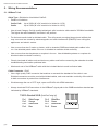
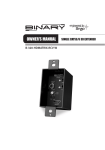
4. Receiver Layout
1
2
3
4
5
6
7 8
1.
HDMI Out
Attach HDMI cable to the display.
2. IR Receiver
Connect an IR receiver to this port for capturing commands to transmit IR signal to the matrix
switcher using IR pass-through. (3.5mm stereo mini)
3.
IR Flasher
Connect an IR flasher or control system to this port to control a display or device using IR
pass-through. (3.5mm mono mini)
4.
Latch-Locking Power Jack
Attach the included 5V DC 2A power supply to this jack.
5.
Firmware Update Port (USB)
Factory use only. Requires custom non-standard USB cable.
6.
HDBaseT Link Port (RJ45)
Attach the HDBaseT cable from the transmitting device.
7.
Power LED
Illuminates solid RED when extender is powered on.
8. Link LED
Illuminates solid GREEN when HDBaseT Link is active. Off indicates that HDBaseT Link is
not active.
pg.5
www.snapav.com Support: 866.838.5052
B-500-RX-230-IR Installation Manual
5. Wiring Recommendations
5.1. HDBaseT Link
Cable Type - Shielded or Unshielded Cat5e/6
• Distance Limitations
Cat5e/ Cat6: Up to 200ft (4K x 2K resolution is limited to 115 ft)
Cat6a:
Up to 230ft (4K x 2K resolution is limited to 130 ft)
•Use at least Category 5e high quality twisted pair solid conductor cable rated to 350 Mhz bandwidth.
The higher the cable standard, the better it will perform.
•For the best results install a shielded cable. This will prevent rare signal dropout and artifacts that
may occur and are caused by electromagnetic and radio interference (EMI/RFI) from ceiling fans,
appliances and electric motors.
•Use no more than two 5 meter or shorter, solid or stranded, 568B terminated patch cables in the
run. Use shielded patch cables if the run is shielded to maintain shield continuity.
•Use no more than two keystones or couplers in the run. Use shielded keystones or couplers with
shielded cable to maintain continuity.
•Cleanly terminate all cable ends and test every cable used before connecting the extender to avoid
troubleshooting termination problems later.
• Mark each end of the HDBaseT cable with the included labels to avoid confusion later.
Cable Connector - RJ45
•Use a high quality RJ45 connector that matches or exceeds the standard of the cable in use.
Shielded connectors must be used with shielded cables, and must maintain continuity of the shield
to both connectors to protect from interference.
• We discourage the use of “EZ” style, open end RJ45’s with HDMI extenders.
•Always terminate RJ45 connectors in the HDBaseT signal path to the 568B termination standard as
indicated by HDBaseT standards.
TIA/EIA Standard 568-B (Gold Pins Facing Up)
Pin 1
Pin 2
Pin 3
Pin 4
White/Orange
Orange
White/Green
Blue
Pin 5
Pin 6
Pin 7
Pin 8
White/Blue
Green
White/Brown
Brown
pg.6
© 2013 Binary
B-500-RX-230-IR Installation Manual
5.2. HDMI Cable
•Use Binary (or similar) 2 meter or shorter, High Speed rated HDMI cables between any device and
the HDMI output port of the Receiver for the best performance.
•The Receiver should work with a longer cable, but in the case of any picture or sync issues, it
should be 2 meters or less between the equipment and the Receiver to accurately troubleshoot.
•Avoid using HDMI keystones. The best practice for HDMI cables is to have one unbroken cable
between the Receiver and other equipment.
6. Power Supply
The B-500-RX-230-IR uses a 5V DC 2A power supply.
Power Supply Voltage Warning! Before applying power to the Receiver, read the label on the power
supply to confirm that it is 5V DC 2A. Connecting the wrong voltage power supply may cause damage to
the Receiver or the supply.
pg.7
www.snapav.com Support: 866.838.5052
B-500-RX-230-IR Installation Manual
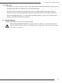
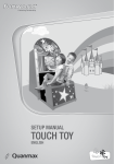
7. Installation Instructions
AC
Power
B-500-MTRX-230-4x4
ALL IR OUT
LINK
LINK
LINK
LINK
IR IN
Cat 5e/6
HDBaseT
HDTV
HDMI
B-500-RX-230-IR
*Can also be used with other HDBaseT transmitters.
Follow these steps to install the receiver:
1.Turn off all equipment to be connected. Do not connect power to the B-500-RX-230-IR until all
other connections are made.
2.Run the HDBaseT cable from the location of the Transmitter to the location of the Receiver and
terminate the ends.
3. Test the HDBaseT cable using a continuity tester or network analyzer.
4.Connect the HDBaseT cable to the B-500-RX-230-IR Receiver and the transmitting device
being used.
5.Connect an HDMI cable between the HDMI Out port of the B-500-RX-230-IR and the HDMI input
of the display.
6.Screw the power connector into the latch locking jack on the Receiver, and then plug the power
supply into an AC outlet. The Power LED at the Receiver should illuminate solid RED.
7.Test the system by playing media at the highest resolution that can be supported by all of the
equipment.
8. After testing is complete and the unit is functional, mount the Receiver in the desired location.
Important! It is essential to have HDBaseT pass-through working correctly before other features are
configured, so make sure this portion of the install is functional before setting up IR serial pass-through.
pg.8
© 2013 Binary
B-500-RX-230-IR Installation Manual
8. IR Pass-Through
This section outlines the connections, optional adapters, and operation of IR pass-through on the
B-500-MTRX-230 HDBaseT Receiver. Integration with the B-500-MTRX-230 matrix switcher is
detailed. Refer to the documentation included with any transmitter used for specific instructions to
integrate IR pass-through.
8.1. Port Pinouts
8.1.1. IR Receiver Port (3.5mm {1/8”} Stereo)
12V DC (Sleeve)
GND (Ring)
IR Signal (Tip)
IR Signal
GND (Ground)
+12V DC
Tip
Ring
Sleeve
The IR Receiver port sends IR commands over the HDBaseT Link to the IR OUTPUT TO SOURCE
and SYSTEM ALL IR OUT ports at the matrix switcher. Plug in a compatible IR receiver such as the
Episode® EE-IR-RCVR-SURFACE to capture in-room IR commands for control of the matrix switcher
and sources at the matrix switcher or Transmitter.
Important! Pinout configurations for IR receivers and control systems vary. Before connecting to
the IR Receiver port, review all device pinouts carefully in order to match the configuration for the
B-500-RX-230-IR.
8.1.2. Yellow Tag IR Adapter
To B-500-RX-230-IR
IR Receiver Port
To IR Control System or
Connecting Block
12V DC (Sleeve)
GND (Ring)
IR Signal (Tip)
GND (Sleeve)
IR Signal (Tip)
The included yellow tagged adapter (illustrated above) is used when plugging a 3.5mm mono mini
cable into the IR Receiver port of the B-500-RX-230-IR. This is used to send IR commands to the matrix
switcher location from other devices instead of an IR Receiver that use a 3.5mm mono mini port for
output.
8.1.3. IR Flasher Port
GND (Sleeve)
IR Signal (Tip)
IR Signal
GND (Ground)
Tip
Ring
The IR flasher port outputs any signal received from the IR INPUT TO ROOM port on the matrix switcher
or the IR Receiver port of a Transmitter. The port can power one single flasher, or a mono cable may be
attached to the input of a powered IR distribution block to use several flashers.
pg.9
www.snapav.com Support: 866.838.5052
B-500-RX-230-IR Installation Manual
8.2. IR Installation
IR pass-through can be used in two ways, to control displays from the transmitting location (via
commands from an automation system), or to control sources and the matrix using IR remotes in the
rooms where displays are located. Commands may be passed in both directions at once if necessary.
To install the IR receivers and flashers, plug the devices into the correct ports as indicated and then
locate the best location for placement to either capture commands or control the device.
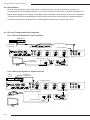
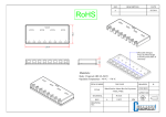
8.3. IR Pass-Through Application Diagrams
8.3.1. IR Control System to Control Displays
HDMI Source
PLAY
Flasher Outputs
IR Flasher to
Control Source
IR Outputs
3.5mm Mono Cable
IR Inputs
Control System
IR Input to Room
ALL IR OUT
LINK
LINK
LINK
LINK
IR IN
HDBaseT Cat5e/6
IR Flasher Port
IR Flasher to
Control Display
B-500-RX-230-IR
HDTV
Note: IR functionality of other transmitters may vary. Refer to the documentation for the transmitter
being
for information
onControl
its IR pass-through
8.3.2.
IR used
Receiver
System to
Sources functionality.
IR Flasher to
Control Source
HDMI
Source
PLAY
IR Out to Source
ALL IR OUT
LINK
LINK
LINK
LINK
IR IN
Capture Commands at Display
HDBaseT Cat5e/6
IR Receiver
IR Receiver Port
B-500-RX-230-IR
HDTV
Note: IR functionality of other transmitters may vary. Refer to the documentation for the transmitter
being used for information on its IR pass-through functionality.
pg.10
© 2013 Binary
B-500-RX-230-IR Installation Manual
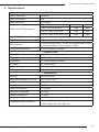
9 . Specifications
TECHNICAL
HDMI Compliance
HDMI 3D
HDCP Compliance
Yes
Video Bandwidth
10.2 Gbps
Resolution
HDMI over UTP Transmission
Cat5e/ Cat6
Cat6a
1080i / 720p 24-bit color
200ft
230ft
Full HD 1080P 24-bit color
200ft
230ft
Full HD 1080P 36-bit deep color
200ft
230ft
Input TMDS Signal
1.2 Volts (peak-to-peak)
Input DDC Signal
5 Volts (peak-to-peak, TTL)
ESD Protection
(1) Human body model — ±15kV (air-gap discharge) & ±8kV
(contact discharge) (2) Core chipset — ±8kV
IR Signal (Bi-directional)
Carrier frequency: 20-60kHz
CONNECTIONS
HDBaseT Link
1x RJ45
HDMI
1x HDMI Type A (19-pin female)
IR Receiver
1x 3.5mm Stereo (Powered)
IR Flasher
1x 3.5mm Mono
Power
Latch-Locking
USB Update Port
Mini USB - Factory Use Only
MECHANICAL
Housing
Metal enclosure
Dimensions (Inches, W x H x D)
4.1” x 1.25” x 3.5”
Weight
1.1 lbs.
Power Supply
5V DC 2A
Power Consumption
7.5w (max)
Operation Temperature
32~104°F
Storage Temperature
-4~140°F
Relative Humidity
20~90% RH (no condensation)
Certifications and Compliance
Product: CE, FCC, Rohs
Power Supply: CE, FCC, Rohs, UL
pg.11
www.snapav.com Support: 866.838.5052
10.Warranty
2
year
2-Year Limited Warranty
This Binary™ Product has a Two-Year Limited Warranty. This warranty
includes parts and labor repairs on all components found to be defective
in material or workmanship under normal conditions of use. This
warranty shall not apply to products which have been abused, modified
or disassembled. Products to be repaired under this warranty must be
returned to SnapAV or a designated service center with prior notification
and an assigned return authorization number (RA).
11.Contacting Technical Support
Phone: (866) 838-5052
Email: [email protected]
130918-1512
© 2013 Binary™