1
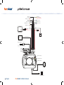
• Input 3 is Positive trigger (12V+ or 24V+)
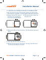
9. Connect the RED wire to 12V+ or 24V+
10. Connect the Wiring harness to the device to turn the
Fleetminder ON!
e
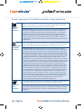
• Watch the LED’s on the side of the unit to see the state of the
device. Please refer to the LED state explanation form for
reference.
Note: The YELLOW and Green LED’s will not be on until the system goes to full
working mode, normally 30 seconds after power on.
(This is in case the unit is in GPRS coverage)
Please refer to page 7 the LED Troubleshooting.
11. To test that the device is working correctly, move the vehicle
outside, ensuring that the GPS antenna has a clear view of the
sky.
For GPRS tracking, the LED indicator should show:
RED (ON), YELLOW (FLASHING), GREEN (ON)
For testing of the unit, the Primary phone number must be used using
SMS. Refer to the User manual for further instructions.
(Please refer User’s Manual [section 8.1])
12. Start tracking
• On-line Tracking
If online tracking was ordered with the device, it should already
be set up to start monitoring the location. Refer to your service
agreement which will include your username, password and the
software link.
• SMS Tracking
Refer to Command list for setting up the device using SMS.
Page 4
fleetminder Installation Manual