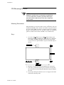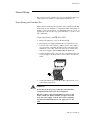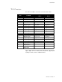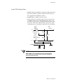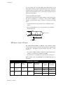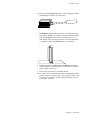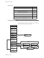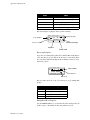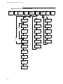
1
CLS
User’s Guide
Watlow Controls
1241 Bundy Blvd.
Winona, MN 55987
Customer Service
Phone: (800) 414-4299
Fax:
(800) 445-8992
Technical Support
Phone: (507) 494-5656
Fax:
(507) 452-4507
Email: [email protected]
Part No. 21952-00. Revision 3.2
October 1996
Copyright © 1996
Watlow Anafaze
Information in this manual is subject to change without notice. No part of this publication may be
reproduced, stored in a retrieval system, or transmitted in any form without written permission
from Watlow Anafaze.
Warranty
Watlow Anafaze, Incorporated warrants that the products furnished under this Agreement will be
free from defects in material and workmanship for a period of three years from the date of shipment. The Customer shall provide notice of any defect to Watlow Anafaze, Incorporated within one
week after the Customer's discovery of such defect. The sole obligation and liability of Watlow
Anafaze, Incorporated under this warranty shall be to repair or replace, at its option and without
cost to the Customer, the defective product or part.
Upon request by Watlow Anafaze, Incorporated, the product or part claimed to be defective shall
immediately be returned at the Customer's expense to Watlow Anafaze, Incorporated. Replaced or
repaired products or parts will be shipped to the Customer at the expense of Watlow Anafaze,
Incorporated.
There shall be no warranty or liability for any products or parts that have been subject to misuse,
accident, negligence, failure of electric power or modification by the Customer without the written
approval of Watlow Anafaze, Incorporated. Final determination of warranty eligibility shall be
made by Watlow Anafaze, Incorporated. If a warranty claim is considered invalid for any reason,
the Customer will be charged for services performed and expenses incurred by Watlow Anafaze,
Incorporated in handling and shipping the returned unit.
If replacement parts are supplied or repairs made during the original warranty period, the warranty
period for the replacement or repaired part shall terminate with the termination of the warranty
period of the original product or part.
The foregoing warranty constitutes the sole liability of Watlow Anafaze, Incorporated and the Customer's sole remedy with respect to the products. It is in lieu of all other warranties, liabilities, and
remedies. Except as thus provided, Watlow Anafaze, Inc. disclaims all warranties, express or
implied, including any warranty of merchantability or fitness for a particular purpose.
Please Note: External safety devices must be used with this equipment.
CLS User’s Guide
Contents
Contents
Overview
1
System Diagram.....................................................................2
Parts List ...............................................................................2
Safety .....................................................................................3
Introduction
5
Specifications ........................................................................7
Analog Inputs ..................................................................7
Digital Inputs ..................................................................9
User-Selectable Digital Outputs .....................................9
System Digital Outputs ....................................................9
Analog Outputs ................................................................10
Miscellaneous Specifications ................................................11
Physical Dimensions .......................................................11
Installation
13
Precautions and Warnings ....................................................14
Recommended Tools ............................................................15
Panel Hole Cutters ..........................................................15
Other Tools .....................................................................15
CLS Mounting Procedure .....................................................16
Mounting Environment ...................................................16
Steps: ...............................................................................16
TB-18 Mounting Instructions ...............................................17
TB-50 Mounting Instructions ...............................................18
General Wiring Recommendations .......................................20
Grounding .......................................................................21
Thermocouple Wiring .....................................................22
Input Wiring ....................................................................22
Output Wiring .................................................................23
Communications Wiring .................................................23
Wiring: Noise Suppression ...................................................24
General Wiring .....................................................................25
Power Wiring and Controller Test ..................................25
Outputs ..................................................................................27
PID Control and Alarm Output Connections 2................30
Watchdog Timer .............................................................30
TB-18 Connections .........................................................31
TB-50 Connections .........................................................32
i
Contents
CLS User’s Guide
Inputs ....................................................................................34
Input Scaling ...................................................................34
4 and 8 CLS Scaling Values ...........................................35
16 CLS Scaling Values ...................................................38
Scaling and Calibration ...................................................39
T/C Inputs .......................................................................39
RTD Inputs (4 and 8 CLS only) ......................................40
Current Inputs .................................................................41
Voltage Inputs .................................................................41
Unused Inputs .................................................................41
Back Terminal Block Connections .................................42
Serial Communications .........................................................42
RS-232 Interface .............................................................43
RS-485 Interface .............................................................43
Using the CLS
49
Introduction ...........................................................................49
Front Panel ............................................................................50
Front Panel Keys .............................................................50
Displays ................................................................................53
Bar Graph Display ..........................................................53
Single Loop Display .......................................................54
Alarms .............................................................................56
Job Display ...........................................................................57
Operator Menus ....................................................................58
Change Setpoint ..............................................................58
Manual/Automatic Control .............................................58
Ramp/Soak ......................................................................60
Setup
61
How to Enter the Setup Menus? .....................................61
How to edit a menu? .......................................................61
Set up Global Parameters Menu ...........................................63
Load a Job .......................................................................64
Save Setup to Job ............................................................64
Job Select Inputs .............................................................65
Job Select Input Polarity .................................................65
Output Override Digital Input .........................................66
Output Override Input Polarity .......................................66
Start-up Alarm Delay ......................................................66
Keyboard Lock Status .....................................................67
Power-Up Output Status .................................................67
Controller Address ..........................................................67
Communications Baud Rate ............................................68
ii
CLS User’s Guide
Contents
Communications Protocol ...............................................68
Communications Error Checking ...................................68
AC Line Frequency .........................................................69
Digital Output Polarity ....................................................69
EPROM Information .......................................................69
Set up Loop Input .................................................................70
Input Type .......................................................................71
Pulse Sample Time .........................................................72
Loop Name .....................................................................72
Input Units ......................................................................72
Input Reading Offset .......................................................73
Linear Scaling Menus .....................................................73
Display Format ...............................................................75
High Process Value .........................................................75
High Reading ..................................................................76
Low Process Value .........................................................76
Low Reading ...................................................................76
Input Filter ......................................................................77
Set up Loop Control Parameters ...........................................78
Heat or Cool Control PB .................................................79
Heat or Cool Control TI ..................................................79
Heat or Cool Control TD ................................................79
Heat or Cool Output Filter ..............................................80
Heat and Cool Spread .....................................................80
Set up Loop Outputs .............................................................81
Enable/Disable Heat or Cool Outputs .............................82
Heat or Cool Output Type ..............................................82
Heat or Cool Cycle Time ................................................83
SDAC Menus ........................................................................83
SDAC Mode ...................................................................83
SDAC High Value ..........................................................84
SDAC Low Value ...........................................................84
Heat or Cool Output Action ............................................84
Heat or Cool Output Limit ..............................................85
Heat or Cool Output Limit Time ....................................85
Heat or Cool Output Override ........................................85
Heat or Cool Nonlinear Output Curve ............................86
Set up Loop Alarms ..............................................................87
Alarm Types ...................................................................87
High Process Alarm Setpoint ..........................................90
High Process Alarm Type ...............................................90
High Process Alarm Output Number ..............................90
Deviation Band Value .....................................................91
High Deviation Alarm Type ...........................................91
iii
Contents
CLS User’s Guide
High Deviation Alarm Output Number ..........................91
Low Deviation Alarm Type ............................................92
Low Deviation Alarm Output Number ...........................92
Low Process Alarm Setpoint ..........................................92
Low Process Alarm Type ...............................................93
Low Process Alarm Output Number ..............................93
Alarm Deadband .............................................................93
Alarm Delay.....................................................................94
Manual I/O Test ....................................................................95
Digital Input Testing .......................................................95
Test Digital Output .........................................................96
Toggle Digital Output .....................................................96
Keypad Test ....................................................................96
PID Tuning and Control
97
Introduction ...........................................................................97
Control Modes ......................................................................98
On/Off Control ................................................................98
Proportional Control .......................................................98
Proportional and Integral Control ...................................99
Proportional, Integral and Derivative Control ................100
Control Outputs ...............................................................100
Digital Output Control Forms .........................................100
Setting Up and Tuning PID Loops .......................................103
Proportional Band (PB) Settings .....................................103
Integral Term (TI) Settings .............................................104
Derivative Term (TD) Settings .......................................104
General PID Constants by Application .................................105
Proportional Band Only (P) ............................................105
Proportional with Integral (PI) ........................................105
PI with Derivative (PID) .................................................105
Troubleshooting
107
No Key Reset ..................................................................107
Returning your Unit ........................................................108
Troubleshooting Stand-Alone Systems ................................108
Checking an Analog Input ..............................................108
Checking Digital I/O .......................................................109
Checking Computer Supervised Systems .............................110
Computer Problems ........................................................110
Software Problems ..........................................................111
Changing the EPROM ....................................................111
iv
CLS User’s Guide
Contents
Linear Scaling Examples
115
Example 1 .............................................................................115
Example 2 .............................................................................116
Example 3 .............................................................................117
Appendix A: Ramp Soak
119
Introduction ...........................................................................119
R/S Features ....................................................................119
Specifications ..................................................................120
Configuring Ramp/Soak .......................................................120
Setting the R/S Time Base ..............................................121
Editing R/S Parameters ...................................................121
Choosing a Profile to Edit ...............................................121
Copying the Setup from Another Profile ........................122
Editing the tolerance Alarm Time ..................................122
Editing the Ready Setpoint .............................................123
Editing the Ready Event States .......................................123
Choosing an External Reset Input ..................................124
Editing a Segment ...........................................................124
Setting Segment Time .....................................................124
Setting a Segment Setpoint .............................................125
Configuring Segment Events ..........................................125
Editing Event Outputs .....................................................126
Changing Event States ....................................................126
Editing Segment Triggers ...............................................126
Assigning an Input to a Trigger ......................................127
Changing a Trigger’s True State .....................................127
Latching or Unlatching a Trigger ...................................127
Setting Segment Tolerance .............................................128
Ending a Profile ..............................................................128
Repeating a Profile ..........................................................128
Using Ramp/Soak .................................................................129
Assigning a profile to a loop ...........................................129
Assigning a Profile to a Linear Input Loop ....................130
Running a Profile ............................................................131
Ramp/Soak Displays .......................................................131
Holding a Profile or Continuing from Hold ....................134
Resetting a profile ...........................................................135
Appendix B: Enhanced Process Control
137
Enhanced Process Control Menus ........................................138
v
CLS User’s Guide
vContents
Process Variable Retransmit .................................................139
Setting Up a PV Retransmit ............................................139
PV Retransmit Menus .....................................................140
Cascade Control ....................................................................143
Setting Up Cascade Control ............................................143
Cascade Control Menus ..................................................144
Ratio control .........................................................................147
Setting Up Ratio Control ................................................147
Ratio Control Menus .......................................................148
Remote Analog setpoint ........................................................149
Differential Control ...............................................................149
Typical Applications .............................................................150
Process Variable Retransmit ...........................................150
Cascade Control ..............................................................153
Ratio Control ...................................................................156
Remote Setpoint ..............................................................158
Differential Control .........................................................159
Glossary
163
Overview
Overview
This manual describes how to install, setup, and operate a 4CLS, an
8CLS, or a 16CLS. Included are seven chapters, two Appendices, and a
glossary of terms. Each chapter covers a different aspect of your control
system and may apply to different users. The following describes the
chapters and their purpose.
• Introduction: Gives a general description of the CLS and its related
specifications.
• Installation: Describes how to install the CLS and its peripheral
devices.
• Using the CLS: Provides an overview of operator displays used for
system monitoring.
• Setup: Describes all the setup displays for the controller, and how to
access them.
• Tuning and Control: Explains PID control and provides tips for
tuning your system.
• Troubleshooting: Gives some basic guidelines for solving control
problems.
• Linear Scaling Examples: Provides an example configuring a pressure sensor, and one configuring a flow sensor.
• Appendix A: Ramp and Soak. This section explains how to setup
and use Ramp/Soak profiles in your application.
• Appendix B: Enhanced Process Control. This appendix describes
optional process variable retransmit and cascade control features.
CLS User’s Guide 1
Overview
System Diagram
The illustration below shows how the parts of the CLS are connected.
When unpacking your system, use the diagrams and parts list below to
ensure all parts have been shipped. Please don't hesitate to call Watlow
Anafaze's Technical Service Department if you have problems with
your shipment, or if the CLS components are missing or damaged.
.
Parts List
• CLS controller
• Controller mount kit
• AC adapter (110V or 220V)
• Terminal Block (TB-50 or TB-18)
• TB-50 or TB-18 mounting kit
• 50 pin flat ribbon cable (50 pin ribbon cable)
• DAC or SDAC (optional)
• User Manual
2 CLS User’s Guide
Overview
Safety
Watlow Anafaze has made efforts to ensure the reliability and safety of
the CLS Controller and to recommend safe usage practices in systems
applications. Please note that, in any application, failures can occur.
These failures may result in full control outputs or other outputs which
may cause damage to or unsafe conditions in the equipment or process
connected to the CLS Controller.
Good engineering practices, electrical codes, and insurance regulations
require that you use independent external safety devices to prevent
potentially dangerous or unsafe conditions. Assume that the Watlow
Anafaze CLS Controller can fail with outputs full on, outputs full off, or
that other unexpected conditions can occur.
Install high or low temperature protection in systems where an
overtemperature or undertemperature fault condition could present a fire
hazard or other hazard. Failure to install temperature control protection
where a potential hazard exists could result in damage to equipment and
property, and injury to personnel.
The CLS includes a reset circuit that sets the control outputs off or to the
data stored in memory if the microprocessor resets--normally the result
of a power failure and power return. If a memory-based restart will be
unsafe for your process, program the CLS Controller to restart with
outputs off. For additional safety, program the computer or other host
device to automatically reload the desired operating constants or process
values on return of operating power. However, these safety features do
not eliminate the need for external, independent safety devices in
potentially dangerous or unsafe conditions.
Watlow Anafaze also offers ANASOFT®, an optional software
program for IBM-AT® or IBM-PC® compatible computers. In the
event of a reset, ANASOFT will reload the CLS Controller with the
current values in computer memory. The user must ensure that this reset
will be safe for the process. Again, use of ANASOFT does not eliminate
the need for appropriate external, independent safety devices.
Contact Watlow Anafaze immediately if you have any questions about
system safety or system operation.
CLS User’s Guide 3
Overview
4 CLS User’s Guide
Introduction
Introduction
The CLS is a modular control system with up to 16 fully independent
loops of PID control (16 CLS). It functions as a stand-alone controller;
the CLS 1/8 DIN front panel has a Liquid Crystal Display (LCD) and
touch keypad for local display and local parameter entry. You can also
use it as the key element in a computer-supervised data acquisition and
control system; the CLS can be locally or remotely controlled via an
RS-232 or RS-485 serial communications interface.
The CLS features include:
Direct Connection of Mixed Thermocouple Sensors: Directly
connect most thermocouples with the CLS versatile hardware.
Thermocouple inputs feature reference junction compensation,
linearization, PV offset calibration to correct for sensor inaccuracies, T/
C upscale break detection, and a choice of Fahrenheit or Celsius display.
Resistive Temperature Detector Sensors are Standard Inputs: Two
types of standard three wire 100 ohm platinum DIN curve sensor are
standard inputs for the CLS. (To use this input, order the CLS with
scaling resistors.)
Automatic Scaling for Linear Analog Inputs: The CLS automatically
scales linear inputs used with other industrial process sensors. Simply
enter two measurement points. For example, to scale a PSI sensor enter
the endpoints: Low PV is 10 PSI, while High PV is 100 PSI. All other
values for that loop will automatically be in PSI.
Dual Outputs Standard: The CLS includes dual control outputs for
each loop, with independent control constants for each output.
Independently Selectable PID Output Modes: You can set each
control output to ON/OFF, Time Proportioning, Serial DAC, or
Distributed Zero Crossing mode. You can set each output control mode
for ON/OFF, P, PI, or PID control with reverse or direct action.
Flexible Alarm Outputs: Independently set high/low process alarms
and a high/low deviation band alarm for each loop. Alarms can activate
a digital output by themselves, or they can be grouped with other alarms
to activate an output.
Alarm or Control Outputs: You can set high/low deviation and high/
low process setpoints to operate digital outputs as on/off control
functions instead of alarms. (The control function has no alarm
notification or global alarm output.)
Global Alarm Output: When any alarm is triggered, the Global Alarm
Output is also triggered, and it stays on until you acknowledge it.
CLS User’s Guide 5
Introduction
Watchdog Timer: The CLS watchdog timer output notifies you of
system failure. You can use it to hold a relay closed while the controller
is running, so you are notified if the microprocessor shuts down.
Front Panel or Computer Operation: Set up and run the CLS from
the front panel or from a local or remote computer. Watlow Anafaze
offers ANASOFT, our IBM AT or IBM-PC compatible software you can
use to operate the CLS. ANASOFT has these features:
• Process Overviews
• Parameter Setup
• Graphic Trend Plotting
• Data Logging
Multiple Job Storage: Store up to 8 jobs in protected memory, and
access them locally by entering a single job number or remotely via
digital inputs. Each job is a set of operating conditions, including
setpoints and alarms.
Non-Linear Output Curves Standard: Select either of two non-linear
output curves for each control output.
Autotuning Makes Setup Simple: Use the Autotune feature to set up
your system quickly and easily. The CLS internal expert system table
finds the correct PID parameters for your process.
Pulse Counter Input Standard: Use the pulse counter input for precise
control of motor or belt speed.
6 CLS User’s Guide
Introduction
Specifications
The following section contains specifications for inputs, outputs, the
serial interface, system power requirements, environmental
specifications, and the CLS physical dimensions.
Analog Inputs
Number of Control Loops: 4 (4CLS), 8 (8CLS), 16 (16CLS), plus one
pulse loop.
Number of Analog Inputs: 4 (4CLS), 8 (8CLS), 16 (16CLS).
Input Switching: differential solid state MUX switching.
Input Sampling Rate:
4CLS: 6x/sec (167 ms) at 60 Hz; 5x/sec (200 ms) at 50 Hz.
8CLS: 3x/sec (333 ms) at 60 Hz; 2.5x/sec (400 ms) at 50 Hz.
16CLS:1.5x/sec (667 ms) at 60 Hz; 1.25x/sec (300 ms) at 50 Hz.
Analog Over Voltage Protection: +20 V referenced to digital ground.
Common Mode Rejection (CMR): For inputs that don't exceed +5 V,
>60 dB DC to 1 kHz, and 120 dB at selected line frequency.
A/D Converter: Integrates voltage to frequency.
Input Range: -10 to +60 mV. Other ranges are available with scaling
resistors.
Resolution: 0.006%, greater than 14 bits. (This is the internal
measurement resolution, not the display resolution.)
Calibration: Automatic zero and full scale.
CLS User’s Guide 7
Introduction
Thermocouple Ranges and Resolution:
T/C
Type
Range in °F
* Accuracy:
25°C
Ambient
Range in °C
°C
J T/C
-350 to 1400
-212 to 760
K T/C
-450 to 2500
-268 to 1371
T T/C
-450 to 750
-268 to 399
S T/C
0 to 3200
-18 to 1760
R T/C
0 to 3210
-18 to 1766
B T/C
150 to 3200
66 to 1760
E T/C
-328 to 1448
-200 to 787
* Accuracy:
0-50°C Full
Temp. Range
°C
°F
°C
°F
±0.5
±0.6
±1.3
±2.5
±2.5
±6.6
±0.9
±1.2
±2.4
±4.5
±4.5
±12.0
±1.1
±1.35
±2.9
±5.6
±5.6
±14.9
±2.0
±2.7
±5.4
±10.1
±10.1
±27.0
* True for 10% to 100% of span.
RTD Ranges and Resolution (4 and 8 CLS only):
Name
RTD1
RTD2
Accuracy:
25°C
Ambient
°C
°F
Accuracy:
0-50°C
Ambient
°C
°F
Resolution
Measurement
Temp. In
°C
-100.0 to
275.0
0.023 °C
25
±0.35
±0.63
±0.5
±0.9
275
±1
±1.8
±1.5
±2.7
-120 to 840
0.062 °C
25
±0.9
±1.62
±2.8
±5.04
840
±1.1
±1.98
±4.3
±7.74
Range in
°F
Range in
°C
-148.0 to
527.0
-184 to
1544
T/C Break Detection: Pulse type for upscale break detection.
Milliamp inputs: 0-20 mA (3 ohms resistance) or 0-10 mA (6 ohms
resistance), with scaling resistors.
Voltage inputs: 0-12V, 0-10V, 0-5V, 0-1V, 0-500mV, 0-100 mV with
scaling resistors.
Range
Input
Resistance
0-12 V
85 Kohms
0-10 V
50 Kohms
0-5 V
40 Kohms
0-1 V
7.4 Kohms
0-500 mV
6.2 Kohms
0-100 mV
1.2 Kohms
Source Impedance: For 60 mV T/C, measurements are within
specification with up to 500 ohms source resistance.
8 CLS User’s Guide
Introduction
Digital Inputs
Number: 8
Configuration: 8 selectable for output override, remote job selection.
Input Voltage Protection: Diodes to supply and common. Source must
limit to 10 mA for override conditions.
Voltage Levels: <1.3V=Low; >3.7V=High (TTL).
Maximum Switch Resistance to Pull Input Low: 1 Kohms.
Minimum Switch Off Resistance: 11 Kohms.
User-Selectable Digital Outputs
Number: 34
Operation: Open collector output; On state sinks to logic common.
Current ≤ 20 mA for 35 loads. Single load ≤ 40 mA. I total ≤ 700 mA.
Function: Selectable as PID control or alarm/control.
Number of PID Control Outputs per PID Loop: 2 (max)
PID Control Output Types: Time Proportioning, Distributed Zero
Crossing, SDAC, or On/Off—all independently selectable for each
output. Heat and cool control outputs can be individually disabled for
use as alarm outputs.
Time Proportioning Cycle Time: 1-255 seconds, programmable for
each output.
PID Control Action: Reverse (heat) or direct (cool), independently
selectable for each output.
Off State Leakage Current: <.01 mA to DC common.
System Digital Outputs
System Digital Outputs: 1 Global Alarm, 1 CPU watchdog.
Operation: Open collector output; On state sinks to logic common.
Current ≤ 20 mA for 35 loads. Single load ≤ 40 mA. I total ≤ 700 mA.
CLS User’s Guide 9
Introduction
Analog Outputs
The Watlow Anafaze Digital to Analog Converter (DAC) is an optional
module for the CLS. It lets you convert a Distributed Zero Crossing
control output signal to an analog process control signal. You can
purchase a 4-20 mAdc, 0-5 Vdc, and 0-10 Vdc versions of the DAC.
Watlow Anafaze also offers the Serial DAC for precision open-loop
control. 0-5 Vdc/4-20 mAdc jumper selectable.
Contact Watlow Anafaze for more information about the DAC and
Serial DAC.
10 CLS User’s Guide
Introduction
Miscellaneous Specifications
Serial Interface
Type: RS-232 3 wire or RS-485 4 wire.
Isolation:
RS-232 None
RS-485 To EIA RS-485 Specification.
Baud Rate: 2400 or 9600, user selectable.
Error Check: BCC or CRC, user selectable.
Number of Controllers: 1 with RS-232 communications;
32 with RS-485 communications.
Protocol: Form of ANSI X3.28-1976 (D1, F1), compatible with Allen
Bradley PLC, full duplex.
System Power Requirements
Voltage: 12-24 Vdc
Input Current (no load): 300 mA max
Maximum Current Requirement: 610 mA. (If the reference voltage is
externally loaded, add 1 mA supply current for every 1 mA of load up to
a maximum load of 100 mA. If using the +5V logic supply to power
digital outputs, add 0.6 mA supply current for every 1 mA of load up to
a maximum load of 350 mA. Therefore, the maximum current
requirement is 300 +100 + (0.6 x 350) = 610 mA.)
Environmental Specifications
Storage Temperature: -20 to 60°C
Operating Temperature: 0 to 50°C
Humidity: 10 to 95% non-condensing.
Physical Dimensions
CLS: 1.75 lbs., 1.98" x 3.78" x 7.10" (.8 kg, 50 mm x 96 mm x 180
mm.)
TB-18: 1.025" x 3.700" (2.57 cm x 9.29 cm)
TB-50: 3.2" x 3.4" (8.03 cm x 8.53 cm)
CLS User’s Guide 11
Introduction
12 CLS User’s Guide
Installation
Installation
These installation instructions are written for non-technical users; if you
are an electrician or you are technically proficient, they may seem
simple to you. Please at least skim all of the instructions, to make sure
you don't miss anything vital.
This section explains installation for the CLS only. If you are installing
another Watlow Anafaze product (such as an SDAC), see the manual
shipped with it to learn how to install it.
These symbols are used throughout the rest of this manual:
DANGER
This symbol warns you about hazards to human life.
WARNING
This symbol warns you of possible damage to property or
equipment.
NOTE
This symbol denotes information you must know in order
to proceed.
CLS User’s Guide 13
Installation
Precautions and Warnings
DANGER
Shut off power to your process before you install the CLS.
High voltage may be present even when power is turned
off! Reduce the danger of electric shock after installation
by mounting the CLS in an enclosure that prevents personal contact with electrical components.
The CLS measures input signals that are not normally referenced to ground, so the CLS inputs and other signal lines
can have high voltage present even when power is turned
off--for example, if you inadvertently short a thermocouple
to the AC power line.
WARNING
During installation and wiring, place temporary covers
over the housing slots and the rear of the CLS so dirt,
pieces of wire, et cetera don't fall through the slots. Remove
these covers after installation.
Install the CLS so the slots in the housing receive unrestricted airflow after installation. Make sure that other
equipment does not block airflow to the housing slots.
Use #20 or #22 AWG wires and trim wire insulation to 1/4”
(5 mm). Wire should fit inside the terminal with no bare
wire exposed, to prevent contact between wires and the
grounded case. Tin any stranded wire.
Support power, input and output cables to reduce strain on
the terminals and to prevent wire removal.
NOTE
Be sure to select a panel location that leaves enough clearance to install and remove the CLS and its components.
14 CLS User’s Guide
Installation
Recommended Tools
Use these tools to install the CLS:
Panel Hole Cutters
Use any of the following tools to cut a hole of the appropriate size in the
panel.
• Jigsaw and metal file--for stainless steel and heavyweight panel
doors.
• Greenlee 1/8 DIN rectangular punch (Greenlee part # 600-68), for
most panel materials and thicknesses.
• Nibbler and metal file--for aluminum and lightweight panel doors.
Other Tools
You will also need these tools:
• Phillips head screwdriver.
• Flathead screwdriver for wiring.
• Multimeter.
CLS User’s Guide 15
Installation
CLS Mounting Procedure
NOTE
Mount the controller before you mount the terminal block
or do any wiring. The controller's placement affects placement and wiring considerations for the other components
of your system.
Mounting Environment
Install the CLS in a location free from excessive (>50ºC) heat, dust, and
unauthorized handling. The controller can mount in any panel material
up to 0.2" thick. (Make sure there is enough clearance for mounting
brackets and terminal blocks; the controller extends 6.2" behind the
panel face and the screw brackets extend 0.5" above and below it.)
Steps:
16 CLS User’s Guide
1.
Cut a hole 3.630+0.020" long by 1.800+0.020" tall in the panel.
This figure shows the mounting hole. (The figure is not a template.)
Cut carefully; the 0.020" (0.5 mm) tolerances don't allow much
room for error. Use a punch, nibbler, or jigsaw, and file the edges of
the hole.
2.
Insert the controller into the hole through the front of the panel.
3.
Screw the top and bottom clips in place: insert the screw's lip into
the cutout in the metal housing just behind the front panel. Tighten
the screw.
4.
If you expect much panel vibration, use a rear support for the CLS
and its interconnecting cables.
Installation
TB-18 Mounting Instructions
These steps describe how to mount the TB-18 on the rear of the CLS.
(Please follow these steps exactly, so you do not damage either the
terminal block or the controller.)
1.
Install the cable support on the underside of the CLS. The TB-18
was shipped to you in a plastic bag. The bag also contained a cable
tie (the long plastic strip) and a cable tie mount (the square plastic
piece with one sticky side).
a.
Stick the cable tie mount to the underside of the CLS. Install it
in a spot that won't block the vents.
b.
Thread the cable tie through the hole in the cable tie mount.
When you're finished wiring the outputs, it should look like
this illustration.
2.
Next, wire outputs to the terminal block. (For help, see Wiring Outputs later in this chapter.) Route wires through the cable support,
leaving about 9" of wire between the TB-18 and the support.
3.
Gently slide the female part of the terminal block into the 50-pin
header on the rear of the controller, as shown here.
WARNING
Do not connect power to the CLS now. Test the unit first, as
explained in the Power Wiring and Controller Test section.
CLS User’s Guide 17
Installation
TB-50 Mounting Instructions
These steps tell you how to mount the TB-50. (Please follow these steps
exactly, so you don’t damage the terminal block, the ribbon cable, or the
controller.)
1.
Choose a mounting location. Be sure there is enough clearance to
install and remove the TB-50; it measures 3.4" long X 3.2" wide X
1.27" tall.
2.
Watlow Anafaze shipped the TB-50 to you in an antistatic bag.
Make sure these parts are also in the bag:
•Five plastic standoffs.
•Five 6-32 screws.
•Five cable tie wraps.
•One 50-pin ribbon cable.
•Five ribbon cable clamps.
3.
Snap four of the plastic standoffs into the four mounting holes on
the TB-50.
There are also four smaller holes on the terminal board, as shown
here. These holes are for the cable tie wraps--the plastic standoffs
won’t fit them. You’ll use these holes to secure wiring to the terminal block. (See Wiring Outputs in this chapter for help installing
cable tie wraps.)
A
B
38B
39
40
41
42
43
44
45
46
47
48
49
50
38A
37
36
35
34
33
32
31
30
29
28
27
26
13B
14
15
16
17
18
19
20
21
22
23
24
25
13A
12
11
10
9
8
7
6
5
4
3
2
1
A
B
1
B
A
B
H oles labeled "A"are m ounting holes.
H oles labeled "B"are tie w rap holes.
18 CLS User’s Guide
A
Installation
4.
Place the TB-50 where you will mount it and use a pencil to trace
around the standoffs.
5.
Drill and tap #6-32 holes in the locations you marked.
6.
Place the TB-50 where you will mount it. Insert the #6 screws in the
standoffs and tighten them.
NOTE
Save the cable tie wraps, ribbon cable, and ribbon cable
clamps. You’ll use them when you wire outputs to the TB50 and when you connect the ribbon cable.
WARNING
Do not connect power to the CLS now. Test the unit first, as
explained in the Power Wiring and Controller Test section.
CLS User’s Guide 19
Installation
General Wiring Recommendations
Use the cables below or their equivalent. For best results, use
appropriate materials, proper installation techniques and the correct
equipment. For example, choose wire type by function, installation
requirements, and the likelihood of mechanical or electrical problems
at your installation.
Function
No. of
Wires
MFR P/N
AWG
Analog inputs
Belden #9154
Belden #8451
2
2
20
22
RTD Inputs (4 & 8 CLS)
Belden #8772
Belden #9770
3
3
20
22
T/C Inputs
T/C Ext. Wire
2
20
Digital PID outputs and Digital I/O
Belden #9539
Belden #9542
Ribbon Cable
9
20
50
24
24
Computer Communication:
RS232 or RS485
Belden #9729
Belden #9730
Belden #9842
Belden #9843
4
6
4
6
24
24
24
24
WARNING
Never wire bundles of low power controller circuits next to
bundles of high power AC wiring. Instead, physically separate high power circuits from the controller. If possible,
install high voltage AC power circuits in a separate panel.
• Use stranded wire. Solid wire is used for fixed service; it makes
intermittent connections when you move it for maintenance.
• Use #20 or #22 AWG wire. Larger or smaller sizes may be difficult
to install, may break easily, or may cause intermittent connections.
• Use shielded wire. (The electrical shield helps protect the CLS from
electrical noise.) Connect one end of the input wiring shield to the
CLS panel's 120 Vac panel ground, and connect one end of the output wiring shield to the CLS panel's 120 Vac panel ground. (Some
installations may require a different shield configuration. Contact
Watlow Anafaze for more information if these instructions do not
apply to your system.)
For more noise suppression measures, see Noise Suppression.
20 CLS User’s Guide
Installation
Grounding
Connect the CLS chassis to an external ground at only one point, to
avoid ground loops that can cause instrument errors or malfunctions.
Since the CLS uses a non-isolated measurement system, it has the
following connections to power supply common:
• Analog common TB1 pins 5, 6, 11, & 12
• Reference common, TB1 pin 17
• Communications ground (TB1 pins 23 & 24) if using RS-232
• Power supply ground, TB2 pin 2
• Control common (TB-18 pin 2; TB-50 pin 3 and 4)
Watlow Anafaze strongly recommends that you:
• Do not connect any one of these pins to earth ground. Do not tie
them together externally.
• Isolate outputs through solid state relays, where possible.
• Isolate RTDs or “bridge” type inputs from ground, if used.
• Isolate digital inputs from ground through solid state relays. If you
can't do that, then make sure the digital input is the only place that
one of the above pins connects to ground.
• If you are using RS-232 from an un-isolated host, don't connect any
other power common point to earth ground.
CLS User’s Guide 21
Installation
Thermocouple Wiring
Use 18 or 20 AWG thermocouple (T/C) extension wire for all the T/C
inputs.
NOTE
Most thermocouple wire is solid unshielded wire. Use
shielded wire if required at your installation; ground one
end only.
WARNING
The CLS uses a floating ground system. Therefore:
Isolate input devices or host computers connected through
communications cables (like RS-232) from earth ground.
Use ungrounded thermocouples with the thermocouple
sheath electrically connected to earth ground.
Use optically isolated RS-232 devices to isolate earth
grounded host computers from CLSs.
When you use grounded T/Cs, tie the thermocouple shields
to a common earth ground in one place. Otherwise any
common mode voltages that exceed 5 volts may cause
incorrect readings or damage to the controller.
WARNING
The 16CLS has single ended inputs, offering little protection from common mode voltage sources. Therefore
Watlow Anafaze highly recommends that you use
ungrounded thermocouples with the external thermocouple sheath electrically connected to earth ground.
You can use 400 to 500' of thermocouple extension wire, depending on
wire type and wire size, and keep to accuracy and source impedance
specifications. Be sure to install thermocouple wiring in a separate
conduit away from AC power (the 120 Vac control supply) and high
power (240 Vac or higher) wiring.
Input Wiring
Use multicolored stranded shielded cable for analog inputs. Watlow
Anafaze recommends that you use #20 AWG wire. (If the sensor
manufacturer requires it, you can also use #22 or #24 AWG wiring.)
Most inputs use a shielded twisted pair; some require a 3 wire input.
22 CLS User’s Guide
Installation
Output Wiring
Use multicolored stranded shielded cable for analog outputs (if you
have installed an SDAC) and PID digital outputs connected to panel
mount SSRs. Analog outputs generally use a twisted pair, while digital
outputs have 9-20 conductors, depending on wiring technique.
For instructions on using the cable tie wraps included in the TB-50’s
packaging, see the Wiring Outputs section.
Communications Wiring
Large systems can pull in an extra pair to the computer communications
wiring. The extra pair services a sound power phone system for
communications between the Watlow Anafaze controller and a
computer.
If you choose this option for maintenance, calibration checking, et
cetera, Watlow Anafaze recommends a David Clark #H5030 system.
CLS User’s Guide 23
Installation
Wiring: Noise Suppression
If the CLS's outputs control dry contact electromechanical relays with
inductive loads--like alarm horns and motor starters--you may get
Electro-magnetic Interference (EMI, or “noise”) The following section
explains how to avoid noise problems; read it before you wire the CLS.
Symptoms of RFI/EMI
If your controller displays the following symptoms, suspect EMI.
• The CLS's display blanks out and then reenergizes as if power had
been turned off for a moment.
• The process value does not display correctly.
EMI may also damage the digital output circuit--so digital outputs will
not energize. If the digital output circuit is damaged, return the
controller to Watlow Anafaze for repair.
Avoiding Noise Problems
To avoid noise problems:
Where possible, use solid state relays (SSRs) instead of
electromechanical (EM) relays. If you must use EM relays, try to avoid
mounting them in the same panel as the CLS equipment.
Separate the 120 Vac power leads from the low level input and output
leads connected to the CLS. Don't run the digital output or PID control
output leads in bundles with 120 Vac wires. (Never run input leads in
bundles with high power leads. See the General Wiring section.)
If you must use EM relays and you must place them in a panel with CLS
equipment, use a .01 microfarad capacitor rated at 1000 Vac (or higher)
in series with a 47 ohm, ½ watt resistor across the NO contacts of the
relay load. This network is known as an arc suppressor or snubber
network.
You can use other voltage suppression devices, but they are not usually
required. For instance, you can place a metal oxide varistor (MOV)
rated at 130 Vac for 120 Vac control circuits across the load, which
limits the peak AC voltage to about 180 Vac (Watlow Anafaze P/N 26130210-00). You can also place a transorb (back to back zener diodes)
across the digital output, which limits the digital output loop to 5 Vdc.
(All the parts mentioned here are available from Watlow Anafaze).
The above steps will eliminate most noise problems. If you have further
problems or questions, please contact Watlow Anafaze.
24 CLS User’s Guide
Installation
General Wiring
The following sections explain how to test your installation before you
connect power to it and how to connect inputs and outputs to it.
Power Wiring and Controller Test
When you have installed each component of the controller and the TB50 (if used), use this checklist to connect them. These instructions are
written so that non-electricians can understand them. If you are an
experienced electrician, they may seem elementary to you. If so, feel
free to skim them.
Connecting Power and TB-50 to CLS
1.
Remove the temporary covers on the CLS housing.
2.
The plug-in power supply, included with your controller, has two
bare wires. The + side connects to TB2-1, and the - side to TB2-2.
As a precaution, you should check the polarity of the wires with a
multimeter (color coding of the wires is not always reliable with
older power supplies). Do not turn on the AC power yet.
3.
Connect the ribbon cable to the controller, as shown here. Plug it in
so the red stripe is on the left side as you face the back of the controller.
4.
Connect the ribbon cable to the TB-50. The cable is keyed, so you
cannot insert it backwards.
WARNING
Do not turn on the AC power yet. Test the connections first,
as explained in the Connections Test section below.
Excessive voltage to the CLS will damage it, and you will
need to return it to Watlow Anafaze for repair. If you use
your own power supply, read the next section completely
and follow its instructions before you apply power to the
CLS.
CLS User’s Guide 25
Installation
Connections Test
Again, follow these instructions if you have purchased your own power
supply, or if you are using a Watlow Anafaze power supply, you don’t
need to perform this test.
1.
Unscrew the two screws on the sides of the CLS front panel.
2.
Gently slide the electronics assembly out of the case. You have now
removed the parts of the CLS which will be damaged by excess
voltage, so plug in the transformer power supply and use a voltmeter to check voltages:
3.
Touch the meter Common lead to the back Terminal Block 2 (TB2)
terminal 2 on the CLS. The voltage on TB2 terminal 1 should then
be +12 to 24 Vdc.
4.
If the voltages are within the limits described above,
a.
Turn off power.
b.
Slide the electronics assembly back into the processor module’s casing.
c.
Reinsert screws into the screw holes on the casing and lighten
them.
d.
Turn the power back on. The CLS display should light up, and
after about a second the Bar Graph display should appear.
If you have not connected analog inputs yet, the CLS may display a “T/C Break” alarm message for each channel. This is
normal; to clear the alarm messages, press ALARM ACK
once for each alarm message.
26 CLS User’s Guide
Installation
Outputs
NOTE
Your CLS is shipped with heat outputs enabled and cool
outputs disabled. You can disable any PID output and use it
for other digital output functions.
All digital outputs and PID outputs are sink outputs referenced to the
5Vdc supply. These outputs are Low (pulled to common) when they are
On.
All digital inputs are Transistor-Transistor Logic (TTL) level inputs
referenced to control common.
The control outputs are located on the 50 pin header which connects to
the TB-18 or TB-50 pin flat ribbon cable. This section explains how to
wire and configure them.
Wiring Outputs
The CLS provides dual PID control outputs for each loop. The digital
outputs sink current from a load connected to the CLS's internal power
supply or from an external power supply referenced to CLS ground.
• If you use an external power supply, do not exceed +12 volts.
• If you tie the external load to ground, or if you cannot connect it as
shown below, then use a solid state relay.
• If you connect an external supply to earth or equipment ground, use
solid state relays to avoid ground currents. (Ground currents may
degrade analog measurements in the CLS).
The outputs conduct current when they are “True”. The maximum
current sink capability is 20 mA (when all outputs are used). They
cannot “source” current to a ground load
CLS User’s Guide 27
Installation
28 CLS User’s Guide
Installation
Using the Cable Tie Wraps
When you have wired outputs to the TB-50, use the cable tie wraps
shipped with it. This diagram shows the cable tie wrap holes.
A
B
38B
39
40
41
42
43
44
45
46
47
48
49
50
38A
37
36
35
34
33
32
31
30
29
28
27
26
13B
14
15
16
17
18
19
20
21
22
23
24
25
13A
12
11
10
9
8
7
6
5
4
3
2
1
A
B
1
B
A
B
H oles labeled "A"are m ounting holes.
H oles labeled "B"are tie w rap holes.
A
Each row of terminals has a cable tie wrap hole at one end. Thread the
cable tie wrap through the cable tie wrap hole. Then wrap the cable tie
wrap around the wires attached to that terminal block.
Configuring Outputs
• You can enable or disable the control outputs. The default setting is
heat outputs enabled, cool outputs disabled.
• You can program each control output individually for On/Off, TP,
SDAC, or DZC control.
• You can individually program each control output for direct or
reverse action.
CLS User’s Guide 29
Installation
PID Control and Alarm Output Connections
Typical digital control outputs use external optically isolated solid-state
relays (SSRs). The SSRs use a 3 to 32 Vdc input for control, and you
can size them to switch up to 100 amps at 480 Vac. For larger currents,
you can use these optically isolated relays to drive contactors. You can
also use Silicon Control Rectifiers (SCRs) and an SDAC for phaseangle fired control.
NOTE
Control outputs are SINK outputs. They are Low when the
output is On. Connect them to the negative side of Solid
State Relays.
The figure below shows sample heat/cool and alarm output connections.
Watchdog Timer
The CLS watchdog timer constantly monitors the CLS microprocessor.
It is a sink output located on TB-18 terminal #3, or on TB-50 terminal
#6. (Do not exceed the 10 mAdc rating for the watchdog timer.) Its
output is Low (on) when the microprocessor is operating; when it stops
operating, the output goes High (off), which de-energizes the SSR.
This figure shows the recommended circuit for the watchdog timer
output.
30 CLS User’s Guide
Installation
TB-18 Connections
This table shows TB-18 connections to the 4CLS and the 8CLS.
PIN
Function
PID Output
4CLS
8CLS
1
+5 Vdc
2
Digital ground
3
Watchdog timer
4
Global alarm
5
Digital output 1
Loop 1 heat
Loop 1 heat
6
Digital output 2
Loop 2 heat
Loop 2 heat
7
Digital output 3
Loop 3 heat
Loop 3 heat
8
Digital output 4
Loop 4 heat
Loop 4 heat
9
Digital output 5
Pulse loop heat
Loop 5 heat
10
Digital output 6
Loop 1 cool
Loop 6 heat
11
Digital output 7
Loop 2 cool
Loop 7 heat
12
Digital output 8
Loop 3 cool
Loop 8 heat
13
Digital output 9
Loop 4 cool
Pulse loop heat
14
Digital output 10
Pulse loop cool
Loop 1 cool
15
Digital output 34*
SDAC clock
SDAC clock
16
Digital input 1
17
Digital input 2
18
Digital input 3
/Pulse input
*If you install a Watlow Anafaze Serial DAC (SDAC), the CLS uses
digital output #34 for a clock line. You cannot use output #34 for
anything else when you have an SDAC installed.
CLS User’s Guide 31
Installation
TB-50 Connections
4 and 8 CLS TB-50 Connections.
Pin
Function
PID Output*
8CLS
4CLS
Pin
Function
1
+5 Vdc
2
+5 Vdc
3
CTRL COM
4
CTRL COM
5
Not Used
6
Watchdog Timer
7
Pulse Input
8
Global Alarm
9
DIG output 1
Loop 1 heat
Loop 1 heat
10
DIG output 34*
11
DIG output 2
Loop 2 heat
Loop 2 heat
12
DIG output 33
13
DIG output 3
Loop 3 heat
Loop 3 heat
14
DIG output 32
15
DIG output 4
Loop 4 heat
Loop 4 heat
16
DIG output 31
17
DIG output 5
Loop 5 heat
Pulse loop
heat
18
DIG output 30
19
DIG output 6
Loop 6 heat
Loop 1 cool
20
DIG output 29
21
DIG output 7
Loop 7 heat
Loop 2 cool
22
DIG output 28
23
DIG output 8
Loop 8 heat
Loop 3 cool
24
DIG output 27
25
DIG output 9
Pulse loop
heat
Loop 4 cool
26
DIG output 26
27
DIG output 10
Loop 1 cool
Pulse loop
cool
28
DIG output 25
29
DIG output 11
Loop 2 cool
30
DIG output 24
31
DIG output 12
Loop 3 cool
32
DIG output 23
33
DIG output 13
Loop 4 cool
34
DIG output 22
35
DIG output 14
Loop 5 cool
36
DIG output 21
37
DIG output 15
Loop 6 cool
38
DIG output 20
39
DIG output 16
Loop 7 cool
40
DIG output 19
41
DIG output 17
Loop 8 cool
42
DIG output 18
43
DIG input 1
44
DIG input 2
45
DIG input 3
46
DIG input 4
47
DIG input 5
48
DIG input 6
49
DIG input 7
50
DIG input 8
PID Output*
8CLS 4CLS
Pulse loop
cool
If you install a Watlow Anafaze Serial Digital to Analog Converter
(SDAC), the CLS uses digital output #34 for a clock line. You cannot
use output #34 for anything else when you have an SDAC installed.
* The indicated outputs are dedicated to PID (or control) when enabled
in the loop setup. If one or both of a loop’s outputs are disabled, the
corresponding digital outputs become available for alarms or ramp/soak
events.
32 CLS User’s Guide
Installation
16 CLS TB-50 Connections.
Pin
Function
PID Output*
Pin
Function
PID Output*
1
+5 Vdc
2
+5 Vdc
3
Digital Ground
4
Digital Ground
5
Not Used
6
Watchdog Timer
7
Pulse Input
8
Global Alarm
9
DIG output 1
Loop 1 heat
10
DIG output 34*
Pulse loop cool
11
DIG output 2
Loop 2 heat
12
DIG output 33
Loop 16 cool
13
DIG output 3
Loop 3 heat
14
DIG output 32
Loop 15 cool
15
DIG output 4
Loop 4 heat
16
DIG output 31
Loop 14 cool
17
DIG output 5
Loop 5 heat
18
DIG output 30
Loop 13 cool
19
DIG output 6
Loop 6 heat
20
DIG output 29
Loop 12 cool
21
DIG output 7
Loop 7 heat
22
DIG output 28
Loop 11 cool
23
DIG output 8
Loop 8 heat
24
DIG output 27
Loop 10 cool
25
DIG output 9
Loop 9 heat
26
DIG output 26
Loop 9 cool
27
DIG output 10
Loop 10 heat
28
DIG output 25
Loop 8 cool
29
DIG output 11
Loop 11 heat
30
DIG output 24
Loop 7 cool
31
DIG output 12
Loop 12 heat
32
DIG output 23
Loop 6 cool
33
DIG output 13
Loop 13 heat
34
DIG output 22
Loop 5 cool
35
DIG output 14
Loop 14 heat
36
DIG output 21
Loop 4 cool
37
DIG output 15
Loop 15 heat
38
DIG output 20
Loop 3 cool
39
DIG output 16
Loop 16 heat
40
DIG output 19
Loop 2 cool
41
DIG output 17
Pulse loop heat
42
DIG output 18
Loop 1 cool
43
DIG input 1
44
DIG input 2
45
DIG input 3
46
DIG input 4
47
DIG input 5
48
DIG input 6
49
DIG input 7
50
DIG input 8
If you install a Watlow Anafaze Serial digital to Analog Converter
(SDAC), the CLS uses digital output #34 for a clock line. You cannot
use output #34 for anything else when you have an SDAC installed.
* The indicated outputs are dedicated to PID (or control) when enabled
in the loop setup. If one or both of a loop’s outputs are disabled, the
corresponding digital outputs become available for alarms or ramp/soak
events.
CLS User’s Guide 33
Installation
Inputs
This section covers input scaling and input installation for all input
types, including thermocouples, RTDs, current inputs, and voltage
inputs.
Input Scaling
The CLS analog input circuitry accepts any mix of thermocouples, 2 or
3 wire RTD inputs, current inputs, and voltage inputs. You can directly
connect the following inputs:
• J, K, T, S, R, B, and E thermocouples.
• Linear inputs with ranges between -10 and 60 mV.
Other inputs require custom scaling resistors. If you didn't order your
unit with the appropriate resistors, you have the following options:
• Watlow Anafaze can install scaling resistors on your unit for a nominal fee.
• Watlow Anafaze can supply a scaling resistor kit that a qualified
technician can use to install scaling resistors.
WARNING
A qualified technician can install scaling resistors in the
CLS. However, damage to the CLS due to improper resistor installation is not covered under warranty, and repairs
can be expensive. If you have any doubts about your ability
to install scaling resistors, send your CLS to Watlow
Anafaze for resistor installation.
34 CLS User’s Guide
Installation
4 and 8 CLS Scaling Values
• For RTD1 inputs, RA and RB are a matched pair (RP). Their matching tolerance is 0.02% (2 ppm/ºC) and their absolute tolerance is
0.1% (10 ppm/ºC). RC has 0.05% tolerance.
• For RTD2 inputs, use 0.05% tolerance resistors.
• For linear mVdc, Vdc, and mAdc ranges, use 0.1% tolerance resistors. Higher tolerances may cause significant errors. Correct any
errors due to resistor tolerance with the CLS's built-in linear scaling.
You can also install other components (like capacitors) for signal
conditioning; please consult Watlow Anafaze for more information.
To
CLS
Circuitry
Analog
Input
Terminal
A+
IN +
RC
( Voltage/Current)
RA
Internal
+5 Vdc
Reference
RD
(RTD/Thermister)
RC
RB
A-
IN C .47 uF
A COM
C .47 uF
NOTE
When adding your own scaling resisters to the 4 and 8 CLS,
the shorting pads of the RC must be cut before installing to
the bottom of the PC board.
CLS User’s Guide 35
Installation
The next table shows scaling resistor values.
Input Range
RA
RB
All T/C, 0-60 mV DC
RTD 1: -100.0 to
275.0ºC
RTD 2: -120 to 840ºC
RC
RD
Jumper
10.0 Kohms
25.0 Kohms
10.0 Kohms
25.0 Kohms
80 ohms
100 ohms
0-10 mA DC
0-20 mA DC
Jumper
Jumper
6.0 ohms
3.0 ohms
0-100 mV
0-500 mV
499 ohms
5.49 Kohms
750 ohms
750 ohms
0-1 VDC
0-5 VDC
0-10 VDC
0-12 VDC
6.91 Kohms
39.2 Kohms
49.9 Kohms
84.5 Kohms
422.0 ohms
475.0 ohms
301.0 ohms
422.0 ohms
The following tables show the location of RA, RB, RC and RD on the
analog input boards of the 4CLS and the 8CLS. (The analog input board
is the upper board of the two-board set.)
36 CLS User’s Guide
Installation
4CLS: Voltage/Current Inputs
Loop #
RC
RD
1
58
RP1
2
56
RP2
3
54
RP3
4
52
RP4
8CLS: Voltage/Current Inputs
Loop
RC
RD
Loop
RC
RD
1
58
RP1
5
50
RP5
2
56
RP2
6
48
RP6
3
54
RP3
7
46
RP7
4
52
RP4
8
44
RP8
4CLS: RTD/Thermister Inputs
Loop #
RA/RB
RC
1
RP1
57
2
RP2
55
3
RP3
53
4
RP4
51
8CLS: RTD/Thermister Inputs
Loop
RA/RB
RC
Loop
RA/RB
RC
1
RP1
57
5
RP5
49
2
RP2
55
6
RP6
47
3
RP3
53
7
RP7
45
4
RP4
51
8
RP8
43
Place resistors RA, RB and RD in the resistor pair locations this way:
A wire trace on the printed circuit board jumpers the RC position. When
you place a resistor in the RC position, cut the wire trace that connects
the two resistor terminals.
CLS User’s Guide 37
Installation
16 CLS Scaling Values
For linear mVdc, Vdc, and mAdc ranges, use 0.1% tolerance resistors.
Higher tolerances may cause significant errors. Correct any errors due
to resistor tolerance with the CLS’ built-in linear scaling. You can also
install other components (like capacitors) for signal conditioning; please
consult Watlow Anafaze for more information.
Analog
Input
Terminals
IN +
IN +
RC
RD
Analog
Common
CLS Measurement
Circuitry
The next table shows scaling resistor values.
Input Range
RC
RD
All T/C, 0-60 mV DC
Jumper
0-10 mA DC
0-20 mA DC
Jumper
Jumper
6.0 ohms
3.0 ohms
0-100 mV
0-500 mV
499 ohms
5.49 Kohms
750 ohms
750 ohms
0-1 VDC
0-5 VDC
0-10 VDC
0-12 VDC
6.91 Kohms
39.2 Kohms
49.9 Kohms
84.5 Kohms
422.0 ohms
475.0 ohms
301.0 ohms
422.0 ohms
The next table shows the location of RC and RD on the analog input
board. (The analog input board is the upper board of the two-board set.)
Loop #
RC
RD
Loop #
RC
RD
1
R58
R42
9
R57
R41
2
R56
R40
10
R55
R39
3
R54
R38
11
R53
R37
4
R52
R36
12
R51
R35
5
R50
R34
13
R49
R33
6
R48
R32
14
R47
R31
7
R46
R30
15
R45
R29
8
R44
R28
16
R43
R27
A wire trace on the printed circuit board jumpers the RC position. When
you place a resistor in the RC position, cut the wire trace that connects
the two resistor terminals.
38 CLS User’s Guide
Installation
Scaling and Calibration
The CLS provides offset calibration for thermocouple, RTD, and other
fixed ranges, and offset and span (gain) calibration for linear and pulse
inputs. (Offset and span calibration convert linear analog inputs into
engineering units using the Mx+B function.)
In order to scale linear input signals, you must:
1.
Install appropriate scaling resistors. (Contact Watlow Anafaze's
Customer Service Department for more information about installing scaling resistors.)
2.
Select the display format. The smallest possible range is
-.9999 to +3.0000; the largest possible range is -9999 to 30000.
3.
Enter the appropriate scaling values for your process.
For more information about input scaling and input offset, see Setup
Loop Inputs in Chapter 4: Setup.
T/C Inputs
WARNING
The CLS uses a floating ground system. Therefore:
Isolate input devices or host computers connected through
communications cables (like RS-232) from earth ground.
Use ungrounded thermocouples with the thermocouple
sheath electrically connected to earth ground.
Use optically isolated RS-232 devices to isolate earth
grounded host computers from the CLS.
When you use grounded T/Cs, tie the thermocouple shields
to a common earth ground in one place. Otherwise any
common mode voltages that exceed 5 volts may cause
incorrect readings or damage to the controller.
WARNING
The 16CLS has single ended inputs, offering little protection from common mode voltage sources. Therefore
Watlow Anafaze highly recommend that you use
ungrounded thermocouples with the external thermocouple sheath electrically connected to earth ground.
CLS User’s Guide 39
Installation
You can connect J, K, T, S, R, B, and E thermocouples directly to the
CLS. Watlow Anafaze provides standard linearization and cold junction
compensation for these thermocouple types. (Other thermocouple types
require custom linearization; please contact Watlow Anafaze for more
information about them.)
Connecting Thermocouples
Connect the positive T/C lead to the In+ terminal. Connect the negative
T/C lead to the TB1 In- (4 or 8CLS) or analog common 16CLS)(
terminal. A typical thermocouple connection is shown in the figure
below.
• Use 20 gauge thermocouple extension wire for all thermocouple
inputs.
• If you use shielded wire, tie it to panel ground or to ground at the
measurement end.
White
IN +
Type J T/C
Red
IN –
Case
Shield (if present)
Frame Ground
RTD Inputs (4 and 8 CLS only)
The standard industrial RTD is an 100-ohm, 3-wire platinum assembly
as shown in the figure below. Watlow Anafaze highly recommends that
you use the 3-wire RTD to prevent reading errors due to cable
resistance.
• If you order an RTD1 or RTD2 configuration, Watlow Anafaze will
configure your CLS for the standard 3-wire RTD.
• If you must use a 4-wire RTD, leave the fourth wire unconnected.
Watlow Anafaze offers 2 standard DIN 385 curve RTD input ranges, as
shown here:
RTD Ranges in Degrees
Name
RTD1
RTD2
Temp. Range
in ºF
Temp.
Range in
ºC
Resolution
-148.0 to
527.0 ºF
-100.0 to
275.0 ºC
0.023 ºC
-184 to 1544
ºF
-120 to 840
ºC
0.062 ºC
40 CLS User’s Guide
Measurement
Temperature
Error @ 25
Error @ 0-50
ºC Ambient
ºC Ambient
25 ºC
±0.35 ºC
±0.5 ºC
275 ºC
±1 ºC
±1.5 ºC
25 ºC
±0.9 ºC
±2.8 ºC
840 ºC
±1.1 ºC
±4.3 ºC
Installation
Below is a typical RTD.
Back Terminal Block
Connections
In+
I nAnalog
Common
Current Inputs
To connect current (milliamp) inputs, install resistors that convert the
milliamp input to a voltage. Watlow Anafaze offers resistors for 0-20
mA and 0-10 mA current inputs.
Voltage Inputs
• Connect the + side of the voltage input to the In+ terminal.
• Connect the - side of the input to the In- terminal for the 4 and 8CLS,
or analog common for the 16CLS. The 0voltage input range is -10 to
60 mV.
• Scale signals larger than 60 mV with scaling resistors that make full
scale input 60 mV. (For more information, see the Input Scaling section.)
The figures below show typical voltage input.
16CLS
Back Terminal Block
Connections
In+
Analog
Common
4 and 8 CLS
Back Terminal Block
Connections
In+
In-
CLS User’s Guide 41
Installation
Unused Inputs
Set the input type for unused inputs to “SKIP” to avoid the default T/C
break alarms. (See Input Type in Chapter 4: Setup for information on
setting the input type.)
Back Terminal Block Connections
Wire inputs to the back terminal block as shown below.
4CLS
8CLS
16 CLS
42 CLS User’s Guide
Installation
Serial Communications
The CLS is factory-configured for RS-232 communications. However,
the communications are jumper-selectable, so you can switch between
RS-232 and RS-485. (See Configuring Communications below.) You
can also order a communications cable from Watlow Anafaze or make
your own cable.
RS-232 Interface
With RS-232 communications, you can connect the CLS directly to the
serial communications connector on an IBM-PC or compatible
computer. (PC-compatible computers typically use
RS-232
communications.) The RS-232 interface is a standard three-wire
interface. See the table below for connection information. (Some
computers reverse transmit (TX) and receive (RX), so check your
computer manual to verify your connections.)
You can use either RS-232 or RS-485 communications in these
situations:
• When you are using local communications (up to 50 feet).
• When you are using a single CLS.
If you are using RS-232 communications with grounded thermocouples,
use an optical isolator between the controller and the computer.
This table shows RS-232 connections for 25-pin and 9-pin connectors.
DB 25
Connector
DB 9
Connector
CLS Back TB
Watlow Anafaze
Cable
RX Pin 3
RX Pin 2
TX Pin 26
White
TX Pin 2
TX Pin 3
RX Pin 25
Red
GND Pin 7
GND Pin 5
GND Pin 23
Black
RS-485 Interface
• If you use more than one CLS, you must use RS-485 communications.
• If you have connected the CLS to a computer more than 50 feet
away, Watlow Anafaze recommends that you use RS-485 communications.
If you use RS-485 communications, attach an optically isolated RS-232
to RS-485 converter to the computer. You can use an internal converter
card or an external plug-in converter.
CLS User’s Guide 43
Installation
The diagram on the next page shows the recommended system hookup.
To avoid ground loops, it uses an optically isolated RS-232 to RS-485
converter at the host computer. The system is powered from the CLS's
power source or from a secure, isolated supply.
Power
Supply
Host
Computer
+
Optically
Isolated
Converter
+
CLS
Power
Supply
Power
Supply
Fifth Wire
-
-
+
CLS
Optional
Capacitor
Wire equipment in a single “daisy chain” using twisted shielded pairs
for the RS-485 cables. Don't use “octopus connections” or “spurs”.
44 CLS User’s Guide
Installation
Use a 200 ohm terminating resistor on the RX line of the last controller
in the system. (If you have only one controller, it is the last controller in
the system.) Use jumper JU1 to select the terminating resistor; place it
in B position for termination and A position for non-termination.
NOTE
Connect the shields to earth ground only at the computer
or other 485 interface. Do not connect the shield to the
controller.
If you connect RS-485 communications and they do not
function properly, or if you have measurement problems
when communications lines are connected, request additional technical information from the Watlow Anafaze
Customer Service Department.
CLS User’s Guide 45
Installation
Configuring Communications
Your controller is shipped configured for RS-232. To switch between
RS-232 and RS-485, change the jumpers as shown here.
You'll need tweezers and a Phillips head screwdriver to switch between
RS-232 and RS-485. Follow these steps:
46 CLS User’s Guide
1.
Power down the unit.
2.
Remove the controller's metal casing. If you haven't removed the
casing before, please don't try to figure it out yourself; see Changing the PROM in the Troubleshooting section for step-by-step
instructions.
3.
Find jumpers JU2, JU3, JU4, and JU5 (above).
4.
(This part of the explanation assumes that you're changing the communications from RS-232 to RS-485. If you're not, follow the next
two steps but move the jumpers from the B position to the A position.) Use tweezers to carefully grasp the jumpers and gently slide
them off the pins.
5.
Use tweezers to gently slide the jumpers onto the B pins. Move
jumpers JU2, JU3, JU4, and JU5 to the B position, as shown above.
6.
If you have changed the controller to 485 communications, put the
200 ohm terminating resistor on the RX line of the last controller in
the system. (If you're only using one controller, it's the last controller in the system.) Place jumper JU1 in the B position . All other
controllers in the system should have JU1 in the A position.
7.
Put the casing back on. If you haven't removed or reinstalled the
CLS's casing before, see Chapter 7: Troubleshooting for instructions.
Installation
Recommended Wire Gauges
Watlow Anafaze recommends the following maximum distances and
wire gauges:
Distance
Wire Gauge
Recommended
Cable
4000 ft.
24 AWG
Belden #9729
Belden #9842
6000 ft.
22 AWG
Belden #9184
You may wish to use a shield, depending on your noise environment and
grounding problems. The above cables are shielded.
NOTE
These recommendations are conservative, to ensure that
your controller will operate reliably. Expect satisfactory
performance even if you must deviate slightly from a
design specification.
CLS User’s Guide 47
Installation
48 CLS User’s Guide
Using the CLS
Using the CLS
Introduction
This chapter will show you how to use the CLS from the front panel. (If
you are using ANASOFT or AnaWin, please see the related User's
Guide.) The next diagram shows how to reach the operator menus from
Single Loop display. (To change global parameters, loop inputs, control
parameters, outputs, and alarms from the setup menus, you must enter a
special sequence of keys. To learn how, see the next chapter: setup.)
CLS User’s Guide 49
Using the CLS
Front Panel
The front panel provides a convenient interface with the controller. You
can program and operate the CLS with the front panel keys shown
below, or you can use ANASOFT, a program designed specifically for
Watlow Anafaze controllers.
Front Panel Keys
Yes/Up
Press Yes to
• Select a menu.
• Answer Yes to Yes/No questions.
• Increase a number or choice you're editing.
No/Down
Press No to
• Skip a menu you don't want to edit, when the prompt is blinking.
• Answer No to Yes/No prompts.
• Decrease a number or choice when editing.
• Perform a No Key Reset.
50 CLS User’s Guide
Using the CLS
WARNING
Pressing the No key on power up will clear the RAM memory and reinitialize the CLS' factory default values.
To do a No Key Reset, power down the controller, press and hold the No
key, and power up the controller while holding the No key. A No Key
Reset is appropriate:
• After you change the EPROM. (See Chapter 6: Troubleshooting.)
• In some cases when troubleshooting (see Chapter 6: Troubleshooting).
• When you install the controller.
Back
The Back key works like an “escape key”. Press it to:
• Abort editing.
• Return to a previous menu.
• Switch between Bar Graph, Single Loop, and Job Control displays.
Enter
Press Enter to:
• Store data or menu choices after editing and go on to the next menu.
• Start scanning mode (if pressed twice).
Change SP
• Press this key to change the loop setpoint.
Man/Auto
Press the Man/Auto key to:
• Toggle a loop between manual and automatic control.
• Adjust the output power level of loops in Manual control.
• Automatically tune a loop.
CLS User’s Guide 51
Using the CLS
Ramp/Soak
If Ramp/Soak is installed on your controller, press the Ramp/Soak key
to:
• Assign a ramp/soak profile to the current loop.
• Perform operations on an assigned profile.
• See the status of a running profile.
NOTE
Your CLS may not have the Ramp/Soak feature. If it does not,
then the Ramp/Soak key will not operate. If you press the
Ramp/Soak key, you'll see the following message:
LOOP
PROCESS
UNITS
OPTION
UNAVAILABLE
ALARM SETPOINT
STATUS
OUT%
Alarm Ack
Press Alarm Ack to acknowledge an alarm condition and reset the
global alarm digital output.
52 CLS User’s Guide
Using the CLS
Displays
The next section discusses the CLS' main displays--Bar Graph, Single
Loop, and Job displays.
Bar Graph Display
On power up, the CLS displays general symbolic information for all
four primary loops. This display is called Bar Graph mode. The diagram
below shows the symbols used in Bar Graph mode.
Alarm Symbol
LOOP
Loop Number
or Name
01
PROCESS
UNITS
08
AAAA MAMA
ALARM SETPOINT
STATUS
OUT%
Loop Status
The next table explains the symbols you see on the top line of the Bar
Graph display. These symbols appear when the controller is in dual
output mode (heat and cool outputs enabled) and single output mode
(heat or cool outputs enabled, but not both).
Symbol
Symbol’s Meaning
<
Loop is in low process or low deviation alarm.
>
Loop is in high process or high deviation alarm.
Loop is above setpoint. If you enable the high or low deviation alarm, this symbol is scaled to it. If you don’t enable
these alarms, these symbols are scaled to the setpoint +5% of
the sensor’s range.
Loop is at setpoint. If you enable the high or low deviation
alarm, this symbol is scaled to it. If you don’t enable these
alarms, these symbols are scaled to the setpoint +5% of the
sensor’s range.
Loop is below setpoint. If you enable the high or low deviation alarm, this symbol is scaled to it. If you don’t enable
these alarms, these symbols are scaled to the setpoint +5% of
the sensor’s range.
(Blank)
Loop is set to SKIP.
F
Sensor has failed.
CLS User’s Guide 53
Using the CLS
The next table explains the symbols you see on the bottom line of Bar
Graph display. These symbols appear when the controller is in both dual
output mode and single output mode. If an alarm occurs, the controller
automatically switches to Single Loop display and shows an alarm code.
Symbol
Symbol’s Meaning
M
One or both outputs enabled. Loop is in manual control.
A
Only one output (heat or cool, but not both) is enabled. Loop is
in automatic control.
T
Loop is in Autotune mode.
H
T
Both heat and cool outputs are enabled. Loop is in Automatic
control and heating.
C
L
Both heat and cool outputs are enabled. Loop is in Automatic
control and cooling.
Navigating in Bar Graph Display
• Press Yes (up) or No (down) to see Bar Graph Display for the Pulse
Input loop.
• Press Enter twice to start Bar Graph scanning mode. In scanning
mode, the controller alternately displays the first four loops and then
the pulse input loop for three seconds each.
• Press any key to stop scanning mode.
• From Bar Graph Display, press Back once to go to Single Loop display.
Single Loop Display
Single Loop display (below) shows detailed information for only one
loop. If the heat and cool outputs are enabled, Single Loop display looks
like this:
Process Variable
Loop Number
or Name
Setpoint
LOOP
02
180
PROCESS
UNITS
160 ºF
AUTO 100
ALARM SETPOINT
STATUS
OUT%
Engineering
Units
Output
percentage
Control Status
The control status indicator shows HEAT or COOL if the loop is in
automatic control, and MAN or TUNE if the loop is in manual control.
54 CLS User’s Guide
Using the CLS
If only one output is enabled (heat or cool, but not both), Single Loop
display looks like this:
Engineering Units
Process Variable
Loop Number
Output Percentage
LOOP
PROCESS UNITS
or Name
Cool
02
160 ºF
0
180 AUTO 100
Output Percentage
Setpoint
ALARM SETPOINT STATUS OUT%
Heat
Control Status
From Single Loop Display,
• Press Yes to go to the next loop.
• Press No to go to the previous loop.
• Press the Back key once to go to Job display (if enabled) or Bar
Graph display.
• Press Enter twice to start Single Loop Scanning display. (The Single
Loop Scanning Display shows information for each loop in
sequence. Data for each loop displays for one second.)
• Press any key to stop scanning mode.
CLS User’s Guide 55
Using the CLS
Alarms
If an alarm occurs, a two-character alarm code appears in the lower left
corner of the display (below). If a Failed Sensor alarm occurs, the
controller also displays a short alarm message.
Process Variable
LOOP
Loop number
or Name
02
LP
Engineering Units
PROCESS
ºF
180
180 AUTO 0
ALARM SETPOINT
Alarm Symbols
UNITS
STATUS
Output Percentage
OUT%
Setpoint
These alarm codes and messages are shown in the table below.
Symbol
Alarm Message
Alarm Type
FS
TC Break
Thermocouple break
FS (RO)
RTD Open
RTD break
FS (RS)
RTD Short
RTD Short
HP
No message
High process alarm
HD
No message
High deviation alarm
LD
No message
Low deviation alarm
LP
No message
Low process alarm
Acknowledging an Alarm
Press Alarm Ack to acknowledge the alarm. If there are other loops with
alarm conditions, the Alarm display switches to the next loop in alarm.
Acknowledge all alarms to clear the global alarm digital output. (You
must acknowledge each alarm before displays and keyboard operation
will resume.)
NOTE
In the 4 and 8 CLS, the controller cannot detect all RTD open
and RTD short failures. Detection of open or shorted RTDs
depends on which wires are open or shorted.
56 CLS User’s Guide
Using the CLS
Job Display
Job display appears only if:
• You have turned on the Remote Job Select function. (This function is
explained in Setup.)
• You have selected a job from the job load menu.
When you load a job, Job display shows you the following screen:
LOOP
JOB
PROCESS
3
UNITS
RUNNING
ALARM SETPOINT
STATUS
OUT%
If you remotely loaded the job, Job display looks like this:
LOOP
PROCESS
UNITS
JOB 3 RUNNING
REMOTELY LOADED
ALARM SETPOINT
STATUS
OUT%
If you modify a job's parameters while the job is running, you'll see this
job message:
LOOP
PROCESS
UNITS
JOB 3 RUNNING
DATA MODIFIED
ALARM SETPOINT
STATUS
OUT%
If an alarm occurs, the controller switches to Single Loop Display.
CLS User’s Guide 57
Using the CLS
Operator Menus
You can reach the following Operator Menus from Single Loop Display.
(If your CLS is already installed, try each procedure as you read about
it.)
Change Setpoint
To change the setpoint, go to Single Loop display of the loop you wish
to change, and then press the Change Setpoint key. (The setpoint is the
desired temperature, pH, et cetera, for the process.) You should see a
display like this:
LOOP
03
PROCESS
UNITS
SETPOINT ?
500 º F
ALARM SETPOINT
STATUS
OUT%
• Press Yes to change the setpoint.
• Then press Yes or No to change the setpoint value.
• When you are satisfied with the setpoint value you have chosen,
press Enter to save your changes and return to Single Loop Display;
or
• To return to Single Loop display without saving your changes, press
No or Back.
Manual/Automatic Control
Press the Man/Auto key to set a loop's control mode, set manual output
levels, or automatically tune a loop. The control mode determines
whether the CLS automatically controls the process according to the
configuration information you give it (Automatic control), or you set the
output to a constant level (Manual control).
If both outputs are disabled when you press the Man/Auto key, you'll
see a display like this one:
LOOP
PROCESS
UNITS
MAN/AUTO CONTROL
OUTPUTS DISABLED
ALARM SETPOINT
58 CLS User’s Guide
STATUS
OUT%
Using the CLS
Press any key to exit this display. If at least one control output (heat or
cool) is enabled, you'll see this display:
LOOP
PROCESS
UNITS
01 CONTROL
STATUS ?
AUTO
ALARM SETPOINT
STATUS
OUT%
• Press Yes to change the mode.
• Press Yes or No to switch between Manual, Automatic, and Tune.
• To exit this menu and return to the Single Loop Display without saving your changes, press Back.
• Press Enter to save your changes. If you have set the mode to Manual, you can now set the manual heat and cool output levels.
Manual Output Levels
The Manual Output Levels menu will only appear if you have set the
current loop to Manual control. This menu lets you set the manual
output levels for the enabled outputs. The cool output menu is just like
the heat output menu, except that the word COOL replaces the word
HEAT in the display. You should see a display like the one below:
LOOP
PROCESS
UNITS
01 SET HEAT
OUTPUT ?
ALARM SETPOINT
STATUS
90%
OUT%
• Press Yes to change the output power.
• Then press Yes or No to select a new output power level.
• When you are satisfied with the power level you have chosen, press
Enter to store your changes.
• To discard your changes and return to Single Loop display, press
Back.
CLS User’s Guide 59
Using the CLS
Autotune
If you set the current loop's control status to TUNE and press Enter, the
controller automatically sets the loop to Manual control, 100% output.
(If you selected a continuous output limit, the controller sets the loop to
the output limit.) The autotune function then calculates the appropriate
PID constants for the loop and puts the loop in automatic control with
the calculated PID values.
The Autotune function will abort if:
• Process variable goes over 75% of the setpoint. Remember, the controller is at 100% output or at the output limit you set.
• It has not calculated PID constants after 10 minutes (due to heater
failure, sensor failure, et cetera.)
If the autotune function aborts, it puts the loop into its previous control
state (Automatic control or Manual control at the previous output
percentages.)
To automatically tune a loop, follow these steps:
1.
Make sure the process is cold (or stable and well below setpoint).
2.
Initiate Autotune:
a.
Use the front panel keypad to go to Single Loop Display
b.
Press the Man/Auto key
c.
Choose Tune
d.
Press Enter.
The Tune indicator will begin flashing and the controller will go back to
Single Loop Display. The Tune indicator will keep flashing as long as
the loop is tuning.
Ramp/Soak
If you have a CLS without the Ramp/Soak option, pressing the Ramp/
Soak key has no effect. If you have a CLS with Ramp/Soak installed,
please refer to the Ramp/Soak Appendix at the end of this manual.
60 CLS User’s Guide
Setup
The Setup menus let you change the CLS detailed configuration
information.
If you have not set up a CLS before, or if you don't know what values to
enter, please read first the Tuning and Control section, which contains
PID tuning constants and useful starting values.
How to Enter the Setup Menus?
1.
In Single Loop Display, select the loop you wish to edit.
2.
While still in Single Loop Display, enter the pass sequence below:
Press Enter, Alarm Ack, Change Setpoint.
3.
The first setup menu appears.
NOTE
For your protection, CLS reverts to Single Loop Display If
you don't make any changes for three minutes.
How to edit a menu?
• Press Yes to select this menu or No to advance to the next menu.
• press Yes or No to toggle between the options in your menu.
• Press Enter to store the value you have selected.
• If you decide not to edit the menu, press Back to stop editing and
return to the main menu.
Each display contains the default value for that specific menu, and
below each display you will see the range of choices for that menu.
The following sections tell more about the submenus for each of the six
main menus. If you have a CLS with the Ramp/Soak option, there will
also be a Ramp/Soak menu. (Please refer to the Ramp/Soak
documentation included with your CLS for use instructions.)
The next page shows the setup menus accessible from Single Loop
Display.
CLS User’s Guide 61
Setup
Setup Global
Parameters?
Setup Loop
Inputs?
Setup Loop
Control Params?
Setup Loop
Outputs?
Load setup
from job?
Input type?
Heat control PB?
Heat control
output?
Pulse sample
time?
Heat control TI?
Save setup
to job?
Loop name?
Job select
dig inputs?
Heat control TD?
Heat control filter?
Input units?
Job sel dig ins
active?
Output override
dig input?
Override dig
in active?
Startup alarm
delay?
*
Ramp/Soak
time base? (only
if R/S installed
Keyboard lock
status?
Power up
output status?
Controller
address?
Cool control PB?
Input reading
offset ? (T/C)
Cool control TI?
Disp format?
(Linear)
Cool control TD?
Input scaling
Hi PV? (Linear &
Pulse)
Input scaling
Hi RDG? (Linear
& Pulse)
Heat/Cool spread?
Input scaling
Lo PV? (Linear &
Pulse)
Input scaling
Lo RDG? (Linear
& Pulse)
Communications
baud rate?
Dig out polarity
on alarm?
* If Ramp/Soak is installed
in your controller, see
Ramp/Soak Appendix at
the end of this Guide.
62 CLS User’s Guide
Hi proc alarm
setpt?
Digital inputs
Hi proc alarm
type?
Hi proc alarm
output?
Heat output
action?
Dev alarm
value?
Heat output limit?
Hi dev alarm
type?
Heat output
limit time?
Heat override
output?
Heat output?
Cool control
output?
Cool output type?
Cool output cycle
time? (TP)
SDAC menus
(SDAC only)
Hi dev alarm
output?
Lo dev alarm
type?
Lo dev alarm
output?
Lo proc alarm
setpt?
Lo proc alarm
type?
Lo proc alarm
output?
Alarm deadband?
Cool output limit?
Alarm delay?
Cool output
limit time?
Cool override
output?
Cool output?
EPROM
information
Manual I/O
Test?
SDAC menus
(SDAC only)
Cool output
action?
Communication
protocol?
AC line freq?
Heat output
cycle time? (TP)
Cool control filter?
Input Filter?
Communications
ERR check?
Heat output type?
Setup Loop
Alarms?
Test digital
output?
Keypad test
Setup
Set up Global Parameters Menu
The Set up Global Parameters menu looks like this:
LOOP
PROCESS
UNITS
SETUP GLOBAL
PARAMETERS ?
ALARM SETPOINT
STATUS
OUT%
Below is the setup global parameters menu tree. Notice the default
values inside the boxes.:
Setup Global Parameters?
Load setup from job? 1
Save setup to job? 1
Job select dig inputs?
NONE
Job sel dig ins active?
LOW
Output override dig
input? NONE
Override dig in active?
LOW
Startup alarm delay?
0 MINS
Keyboard lock status?
OFF
Power up output status?
OFF
Controller address? 1
Communications
baud rate? 9600
Communications
protocol? ANA
Communications err
check? BCC
AC line freq.?
60 HERTZ
Dig out polarity on alarm?
LOW
EPROM information
CLS User’s Guide 63
Setup
Load a Job
Use this menu to load any one of 8 saved jobs from the controller's front
panel.
LOOP
PROCESS
UNITS
LOAD SETUP
FROM JOB ? 1
ALARM SETPOINT
STATUS
OUT%
The following parameters are loaded as part of a job:
• PID constants, filter settings, setpoints and spread values
• Loop control status (Automatic or Manual) and output values (if the
loop is in Manual control).
• Alarm functions (Off, Alarm, Control), setpoints, high\low process
setpoints, high\low deviation setpoints and deadband settings, and
loop alarm delay.
WARNING
All current job settings will be overwritten if you select a
job from memory. Save your current programming to a
job number if you want to keep it.
If you have enabled the remote job control function, this menu will be
disabled; you will not be able to load a job from the front panel. If you
try it, you'll see the message below.
LOOP
PROCESS
UNITS
CANNOT LOAD JOB
REMOTE SELECT
ALARM SETPOINT
STATUS
OUT%
Save Setup to Job
Use this menu to save the job information for every loop to one of 8 jobs
in the CLS' battery-backed RAM.
LOOP
PROCESS
UNITS
SAVE SETUP
TO JOB ? 1
ALARM SETPOINT
STATUS
OUT%
If you have enabled the remote job control function, you will not be able
to save a job. If you try it, you'll see this message:
LOOP
PROCESS
UNITS
CANNOT SAVE JOB
REMOTE SELECT
ALARM SETPOINT
64 CLS User’s Guide
STATUS
OUT%
Setup
Job Select Inputs
Use this menu to set the number of job select inputs. The controller uses
these inputs as a binary code that specifies the job number to run. The
number of inputs you choose in this menu controls the number of jobs
you can select remotely.
LOOP
PROCESS
UNITS
JOB SELECT
DIG INPUTS ? NONE
ALARM SETPOINT
STATUS
OUT%
Below is the truth table that tells you which input states select which
jobs.
Digital Input 3
Digital Input 2
Digital Input 1
Job #
F
F
F
1
F
F
T
2
F
T
F
3
F
T
T
4
T
F
F
5
T
F
T
6
T
T
F
7
T
T
T
8
Selectable values: 1, 2, or 3 inputs, or None. These choices have the
following effect:
Setting
Enables
1 input
Jobs 1-2
2 inputs
Jobs 1-4
3 inputs
Jobs 1-8
None (no inputs)
Remote Select disabled
Job Select Input Polarity
Use this menu to set the polarity of the digital outputs used for job
selection.
LOOP
PROCESS
UNITS
JOB SEL DIG INS
ACTIVE ? LOW
ALARM SETPOINT
STATUS
OUT%
Selectable values: High or Low.
When nothing is connected, the inputs are all False and Job 1 is selected
(as shown in the truth table above).
CLS User’s Guide 65
Setup
Output Override Digital Input
Use this menu to set a digital input that sets all loops in manual output at
output levels you select in the Outputs menu. This menu, and the next
one, let you configure a “panic button” or “kill switch” that sets all
outputs to the output override percentage you set in the Set up Loop
Outputs main menu.
LOOP
PROCESS
UNITS
OUTPUT OVERRIDE
DIG INPUT ? NONE
ALARM SETPOINT
STATUS
OUT%
Selectable values: NONE or input number 1-8.
WARNING
Watlow Anafaze recommends that you install additional
external safety devices or over-temperature devices for
emergency shutdowns. Do not rely solely on the output
override feature to shut down your process.
Output Override Input Polarity
Use this menu to toggle the polarity of the Output Override digital input.
You can set the input to be active when Low or active when High.
LOOP
PROCESS
UNITS
OVERRIDE DIG IN
ACTIVE ? LOW
ALARM SETPOINT
STATUS
OUT%
Selectable values: High or Low.
Start-up Alarm Delay
Use this menu to set a start-up delay for process and deviation alarms
for all loops. The controller does not report these alarm conditions for
the specified number of minutes after the controller powers up. (The
controller will always report failed sensor alarms, no matter what startup delay you set.)
LOOP
PROCESS
UNITS
STARTUP ALARM
DELAY ? 0 mins
ALARM SETPOINT
STATUS
OUT%
Selectable values: 0-60 minutes.
66 CLS User’s Guide
Setup
Keyboard Lock Status
Use this menu to lock the front panel operator function keys Change
SP, Man/Auto, and Ramp/Soak so that pressing these keys has no
effect. If you want to use these functions, turn off the Keyboard Lock.
LOOP
PROCESS
UNITS
KEYBOARD LOCK
STATUS ? OFF
ALARM SETPOINT
STATUS
OUT%
Selectable values: On or Off.
Power-Up Output Status
Use this menu to set the initial power-up state of the control outputs to
Off or Memory. If you choose Off, all control outputs are initially set to
Manual mode at 0% output level. If you choose Memory, the outputs are
restored to the last output state stored in memory.
LOOP
PROCESS
UNITS
POWER UP OUTPUT
STATUS ? OFF
ALARM SETPOINT
STATUS
OUT%
WARNING
Do not set the CLS to start from memory if a memorybased restart is unsafe for your process.
Selectable values: Off or Memory.
Controller Address
Use this menu to set the CLS address. The controller address is used for
multiple controller communications on a single 485 cable, so each CLS
must have a different address. Begin with address 1 for the first
controller and assign each subsequent controller the next higher address.
LOOP
PROCESS
UNITS
CONTROLLER
ADDRESS ? 1
ALARM SETPOINT
STATUS
OUT%
Selectable values: 1-32.
CLS User’s Guide 67
Setup
Communications Baud Rate
Use this menu to set the Communications Baud Rate.
LOOP
PROCESS
UNITS
COMMUNICATIONS
BAUD RATE ? 9600
ALARM SETPOINT
STATUS
OUT%
Selectable values: 2400 or 9600.
Communications Protocol
Use this menu to set the communications protocol type.
LOOP
PROCESS
UNITS
COMMUNICATIONS
PROTOCOL?ANA
ALARM SETPOINT
STATUS
OUT%
Selectable values: ANA (Watlow Anafaze’s protocol), AB (Allen
Bradley’s), MOD (Modbus).
Communications Error Checking
This menu appears only when you choose ANA or AB as your
communications protocol. Use it to set the data check algorithm used in
the CLS communications protocol to Block Check Character (BCC) or
to Cyclic Redundancy Check (CRC).
LOOP
PROCESS
UNITS
COMMUNICATIONS
ERR CHECK ? BCC
ALARM SETPOINT
STATUS
OUT%
Selectable values: BCC or CRC.
CRC is a more secure error checking algorithm than BCC, but it
requires more calculation time and slows the CLS communications.
BCC ensures a high degree of communications integrity, so Watlow
Anafaze recommends that you use BCC unless your application
specifically requires CRC
NOTE
If you are using ANASOFT, be sure to configure ANAINSTL for the same Error Checking method and the same
Baud Rate that you set in this menu and in the next one.
68 CLS User’s Guide
Setup
AC Line Frequency
Use this menu to configure the controller to match an AC line frequency
of 50 or 60 Hz. (This function is provided for international users who
require 50 Hz lines.) Since the controller reduces the effect of power
line noise on the analog measurement by integrating the signal over the
period of the AC line frequency, the controller's noise rejection will
suffer if the line frequency is not set correctly.
LOOP
PROCESS
UNITS
AC LINE FREQ ?
60 HERTZ
ALARM SETPOINT
STATUS
OUT%
Selectable values: 50 Hz or 60 Hz.
NOTE
You must switch power to the CLS on and off for a change
in AC line frequency to take effect.
Digital Output Polarity
Use this menu to set the polarity of the digital outputs used for alarms.
LOOP
PROCESS
UNITS
DIG OUT POLARITY
ON ALARM ? LOW
ALARM SETPOINT
STATUS
OUT%
Selectable values: High or Low.
EPROM Information
This is a view-only display. It shows the controller's EPROM version
and checksum.
LOOP
PROCESS
UNITS
CLS164
V03.02 CS=2233
ALARM SETPOINT
STATUS
OUT%
Press any key to return to the Set up Global Parameters menu.
CLS User’s Guide 69
Setup
Set up Loop Input
The Set up Loop Input main menu lets you access menus which change
parameters related to the loop input:
• Input type
• Input units
• Input scaling and calibration
• Input filtering
The next section explains how to use the Input menus to configure your
controller.
LOOP
PROCESS
UNITS
SETUP LOOP 02
INPUT ?
ALARM SETPOINT
STATUS
OUT%
Below is the setup inputs menu tree. Notice the default values inside the
boxes.
Setup Loop Inputs?
Input Scaling Hi RDG?
100.0%FS (linear&pulse)
Input Type? J T/C
Input Scaling Lo PV? 0
(linear & pulse)
Pulse Sample Time? 1s
(only for pulse input)
Input Scaling Lo RDG?
.0%FS (linear & pulse)
Loop Name?
Input Units? ºF
Input Reading Offset?
ºF (only for T/C inputs)
Disp Format?-999 to
3000 (only for linear)
Input Scaling Hi PV?
1000 (linear & pulse)
70 CLS User’s Guide
Input Filter?
3 Scans
Setup
Input Type
Use this menu to configure the input sensor for each loop as one of these
input types:
• Thermocouple types (J, K, T, S, R, B and E).
• RTD (4 and 8CLS). Two ranges: RTD1 (Platinum Class A) and
RTD2 (Platinum Class B).
• Linear inputs.
• Skip (an input type available for unused channels.) The scanning display doesn't show loops you've set to Skip.
LOOP
PROCESS
UNITS
01 INPUT
TYPE ?
ALARM SETPOINT
J T/C
STATUS
OUT%
The following tables show the input types and ranges.
Input Type
Range in ºF
* Accuracy:
25ºC
Ambient
Range in ºC
ºC
ºF
ºC
ºF
±0.5
±0.6
±1.3
±2.5
±2.5
±6.6
±0.9
±1.2
±2.4
±4.5
±4.5
±12.0
±1.1
±1.35
±2.9
±5.6
±5.6
±14.9
±2.0
±2.7
±5.4
±10.1
±10.1
±27.0
ºC
J T/C
-350 to 1400
-212 to 760
K T/C
-450 to 2500
-268 to 1371
T T/C
-450 to 750
-268 to 399
S T/C
0 to 3200
-18 to 1760
R T/C
0 to 3210
-18 to 1766
B T/C
150 to 3200
66 to 1760
E T/C
-328 to 1448
-200 to 787
* Accuracy:
0-50ºC Full
Temp. Range
Pulse
0-2 KHz
Skip
Loop is not scanned or displayed
Linear
See the Linear Scaling section
* True for 10% to 100% of span.
CLS User’s Guide 71
Setup
RTD Ranges (4 and 8CLS)
Accuracy: 25ºC
Ambient
ºC
ºF
Accuracy: 050ºC Ambient
ºC
ºF
Name
Range in ºF
Range in ºC
Resolution
Probe
Temp. In ºC
RTD1
-148.0 to
527.0
-100.0 to
275.0
0.023 ºC
25
±0.35
±0.63
±0.5
±0.9
275
±1
±1.8
±1.5
±2.7
-184 to
1544
-120 to 840
0.062 ºC
25
±0.9
±1.62
±2.8
±5.04
840
±1.1
±1.98
±4.3
±7.74
RTD2
Pulse Sample Time
You can connect a digital pulse signal of up to 2 KHz to the controller's
pulse input. In this menu, you specify the pulse sample period. (This is
the second menu of the Set up Loop Inputs menu for the pulse input
loop only.) Every sample period, the number of pulses the controller
receives is divided by the sample time. The controller scales this
number and uses it as the pulse loop's process variable.
LOOP
PROCESS
UNITS
05 INPUT PULSE
SAMPLE TIME ? 1s
ALARM SETPOINT
STATUS
OUT%
Selectable Range: 1-20 seconds.
Loop Name
Use this menu to name your loop using two-characters. After specifying
a new name, it is placed on the single loop display instead of the loop’s
number.
LOOP
PROCESS
UNITS
A5 LOOP
NAME ? A5
ALARM SETPOINT
STATUS
OUT%
Input Units
Use this menu to choose a three-character description of the loop’s
engineering units
LOOP
PROCESS
UNITS
02 INPUT
UNITS ? ºF
ALARM SETPOINT
72 CLS User’s Guide
STATUS
OUT%
Setup
Selectable values: The table below shows the character set for input
units.
Input
Character Sets for Units
Thermocouple, and RTD
ºF or ºC
Linear & Pulse
0 to 9, A to Z,%, /, degrees, space
Input Reading Offset
This menu does not appear if the input type is linear, pulse, or skip.
Use it to make up for the input signal's inaccuracy at any given point.
For example, at temperatures below 400 ºF, a type J thermocouple may
be inaccurate (“offset”) by several degrees F. Use an independent
thermocouple or your own calibration equipment to find the offset for
your equipment. To correct for offset errors, change the factory default
setting to a positive or negative value for the loop you are editing. (A
positive value increases the reading and a negative value decreases it.)
LOOP
PROCESS
UNITS
02 INPUT READING
OFFSET ?
0 ºF
ALARM SETPOINT
STATUS
OUT%
Selectable range: For thermocouples, infrared inputs and RTD2s, the
offset correction ranges from -300 to +300.
For RTD1s and IR inputs set to Average mode, the offset range is 300.0
to +300.0.
Linear Scaling Menus
The linear scaling menus appear under the Set up Loop Inputs main
menu. Linear scaling is available for linear and pulse inputs only. It lets
you scale the “raw” input readings (readings in millivolts or Hertz) to
the engineering units of the process variable.
NOTE
Linear scaling menus appear only if the loop's input type is
set to Linear (or, for some menus, to Pulse).
For linear inputs, the input reading is in percent (0 to 100%)
representing the 0-60 mV input range of the CLS. For pulse inputs, the
input reading is in Hertz (cycles per second.)
CLS User’s Guide 73
Setup
The scaling function is defined by two points on a conversion line. It
relates the high PV to the high reading and the low PV to the low
reading to define the line. The engineering units of the process variable
can be any arbitrary units. The graph below shows PSI as an example.
Before you enter the values that determine the two points for the
conversion line, you must choose an appropriate display format. The
CLS has six characters available for process variable display; select the
setting with the desired number of decimal places before and after the
decimal point. Use a display format that matches the range and
resolution of the process variable. The display format you choose is
used for the setpoint, alarms, deadband, spread, and proportional band.
The PV (Process Variable) range for the scaled input is between the PV
values that correspond to the 0% and 100% input readings. For the pulse
input, it is between the 0 Hz and 2000 Hz readings. This PV range
defines the limits for the setpoint and alarms, as shown here.
H iPV
Process
Variable
R ange
Lo PV
0 PSI
0%
0mV
0 Hz
Lo
RDG
InputR eading
100%
Hi
Linearin
R D G 60 m V
2000 H z}Pulse in
NOTE
For example linear scaling calculations, see Linear Scaling
section.
74 CLS User’s Guide
}
Setup
Display Format
This menu appears under the Set up Loop Inputs main menu. It lets you
select a display format for a linear input. Choose a format appropriate
for your input range and accuracy. (You will only see the Display
Format menu if you are editing a linear input.)
LOOP
PROCESS
UNITS
04 DISP FORMAT ?
-999 to 3000
ALARM SETPOINT
STATUS
OUT%
Selectable values: The CLS has several available display formats, as
shown below. This table also shows the high and low PV values.
Display Format
Default High PV
Default Low PV
-9999 to +30000
10000
0
-999 to +3000
1000
0
-999.9 to +3000.0
1000.0
.0
-99.99 to +300.00
100.00
.00
-9.999 to +30.000
10.000
.000
-.9999 to +3.0000
1.0000
.0000
High Process Value
This menu appears under the Set up Loop Inputs main menu. Use it to
enter a high process value. The high process value and the high reading
value together define one of the points on the linear scaling function's
conversion line.
LOOP
PROCESS
UNITS
01 INPUT SCALING
HI PV ?
1000 ºF
ALARM SETPOINT
STATUS
OUT%
Selectable values: See table on the previous page.
CLS User’s Guide 75
Setup
High Reading
Use this menu to enter the input level that corresponds to the high
process value you entered in the previous menu. For linear inputs, the
high reading is a percentage of the full scale input range. For pulse
inputs, the high reading is expressed in Hz.
The 100% full scale input value is 60 mV for the linear input type.
LOOP
PROCESS
UNITS
04 INPUT SCALING
HI RDG ? 100.0%FS
ALARM SETPOINT
STATUS
OUT%
Selectable range: Any value between -99.9 and 999.9. However, you
cannot set the high reading to a value less than or equal to the low
reading.
Low Process Value
Use this menu to set a low process value for input scaling purposes. The
low process value and the low reading value together define one of the
points on the linear scaling function's conversion line.
LOOP
PROCESS
UNITS
01 INPUT SCALING
LO PV ?
0 ºF
ALARM SETPOINT
STATUS
OUT%
Selectable values: See table under Display Format.
Low Reading
Use this menu to enter the input level that corresponds to the low
process value you selected in the previous menu. For linear inputs, the
low reading is a percentage of the full scale input range; for pulse
inputs, the low reading is expressed in Hz.
LOOP
PROCESS
UNITS
01 INPUT SCALING
LO RDG ? 0.0%FS
ALARM SETPOINT
STATUS
OUT%
The full scale input value for the linear input type is 60 mV. For pulse
inputs, it is 2000 Hz.
Selectable range: 99.9-999.9. You cannot set the low reading to a value
greater than or equal to the high reading.
76 CLS User’s Guide
Setup
Input Filter
The CLS has two different types of input filter:
• A noise rejection filter that rejects high frequency input signal noise.
This filter keeps a “trend log” of input readings. If a reading is outside the filter's “acceptance band”, and later readings are within the
acceptance band, the CLS ignores the anomalous reading. (The
acceptance band for thermocouples is 5 degrees above and 5 degrees
below the input reading. For linear inputs, it's 0.5% above and 0.5%
below the input reading.) If later readings are also outside the acceptance band, the CLS accepts the anomalous reading and calculates a
new acceptance band. (You cannot adjust this input filter.)
• A standard resistor-capacitor (RC) filter that lets you dampen the
input response if inputs change unrealistically or change faster than
the system can respond. If the input filter is enabled, the process
variable responds to a step change by going to 2/3 of the actual value
within the number of scans you set.
If all input loops are enabled (none of them are set to SKIP) the CLS
scans each input loop 6 times per second. The input filter applies to all
input types except those set to SKIP.
LOOP
PROCESS
UNITS
01 INPUT FILTER ?
3 SCANS
ALARM SETPOINT
STATUS
OUT%
Selectable range: 0-255 scans. 0 disables the filter.
CLS User’s Guide 77
Setup
Set up Loop Control Parameters
Use these menus to change control parameters for heat and cool outputs
of the selected loop, including:
• Proportional Band (PB or Gain), Integral (TI or Reset), and Derivative (TD or Rate) settings.
• Output Filter.
• Spread between heat and cool outputs.
LOOP
PROCESS
UNITS
SETUP LOOP 01
CONTROL PARAMS ?
ALARM SETPOINT
STATUS
OUT%
Below is the setup control parameters menu tree.
NOTE
Both heat and cool outputs have the same menus, so only
one of each menu is shown here. The controller will show
both heat and cool menus even if the heat or cool output is
disabled. (See Set up Loop Outputs for help enabling or
disabling the heat or cool output.)
Refer to Tuning and Control for help in selecting control
parameter values.
Setup Loop Control
Params?
Heat/Cool Control PB?
Heat/cool Control TI?
Heat/Cool Control TD?
Heat/Cool Control Filter?
Heat/Cool Spread?
78 CLS User’s Guide
Setup
Heat or Cool Control PB
This menu allows you to set the Proportional Band (also known as
Gain).
LOOP
PROCESS
UNITS
02 HEAT CONTROL
PB?
50 ºF
ALARM SETPOINT
STATUS
OUT%
NOTE
The CLS internally represents the proportional band (PB)
as a gain value. When you edit the PB, you'll see the values
change in predefined steps--small steps for narrow PB values and large steps for wide PB values.
The controller calculates the default PB for each input type according to
the following equation:
(High Range - Low Range)
Default PB =
Gain
Heat or Cool Control TI
This menu lets you set the Integral term, or Reset.
LOOP
PROCESS
UNITS
02 HEAT CONTROL
TI ? 180 Sec/R
ALARM SETPOINT
STATUS
OUT%
Selectable range: 0 (off) - 6000 seconds.
Heat or Cool Control TD
This menu lets you set the derivative constant.
LOOP
PROCESS
UNITS
03 HEAT CONTROL
TD ?
0 sec
ALARM SETPOINT
STATUS
OUT%
Selectable range: 0-255 seconds.
CLS User’s Guide 79
Setup
Heat or Cool Output Filter
Use this menu to dampen the heat or cool output's response. The output
responds to a step change by going to approximately 2/3 of its final
value within the number of scans you set here.
LOOP
PROCESS
UNITS
04 HEAT CONTROL
FILTER ? 2 SCANS
ALARM SETPOINT
STATUS
OUT%
Selectable range: 0-255. Setting the output filter to 0 turns it off.
Heat and Cool Spread
Use this menu to set the spread between the heat and cool output and the
spread of the On/Off control action.
LOOP
PROCESS
UNITS
01 SPREAD ?
5 ºF
ALARM SETPOINT
STATUS
OUT%
Selectable ranges: 0 - 255, 25.5, 2.55, .255 or .0255, depending on the
way you set up the Input menus.
80 CLS User’s Guide
Setup
Set up Loop Outputs
Press Yes at this prompt to access menus to change loop output
parameters for the current loop, including:
• Enable or disable outputs
• Output type
• Cycle time (for TP outputs)
• SDAC parameters (for SDAC outputs)
• Control action
• Output level limit and limit time
• Output override
• Nonlinear output curve
.
LOOP
PROCESS
UNITS
SETUP LOOP 03
OUTPUTS ?
ALARM SETPOINT
STATUS
OUT%
Below is the setup outputs menu tree. Both heat and cool outputs have
the same menus, so only one of each menu is shown here.
Setup Loop Outputs?
Heat/Cool Control
Output?
Heat/Cool Output
Action?
Heat/Cool Output
Limit?
SDAC Mode?
Heat/Cool Output Type?
Heat/Cool Output
Limit Time?
SDAC High Value?
Heat/Cool Output Cycle
Time? (TP only )
Heat/Cool Override
Output?
SDAC Low Value?
SDAC Menus
(SDAC only )
Heat/Cool Output?
CLS User’s Guide 81
Setup
Enable/Disable Heat or Cool Outputs
From this menu you can enable or disable the heat or cool output for the
current loop. If you want the loop to have PID control, you must enable
one output. You can also disable a heat or cool control output and use
the output pin for something else, like an alarm.
LOOP
PROCESS
UNITS
01 HEAT CONTROL
OUTPUT ? ENABLED
ALARM SETPOINT
STATUS
OUT%
Selectable values: Enabled or Disabled.
Heat or Cool Output Type
This menu lets you set the output type.
LOOP
PROCESS
UNITS
03 HEAT OUTPUT
TYPE ? TP
ALARM SETPOINT
STATUS
OUT%
This table shows the available output types.
Display
Code
Output
Type
Definition
TP
Time
proportioning
Percent output converted to a percent duty cycle over the programmed cycle time.
DZC
Distributed
Zero Crossing
Output on/off state calculated for
every AC line cycle.
SDAC
Serial DAC
Output type for optional Serial
Digital to Analog Converter.
ON/OFF
On / Off
Output either full ON or full OFF.
For an expanded description of these output types, see Tuning and
Control.
82 CLS User’s Guide
Setup
Heat or Cool Cycle Time
From this menu you can set the Cycle Time for Time Proportioning
outputs.
LOOP
PROCESS
UNITS
02 HEAT OUTPUT
CYCLE TIME ? 10 s
ALARM SETPOINT
STATUS
OUT%
NOTE
The Cycle Time menu will only be present if the output
type for the current loop is Time Proportioning.
Selectable range: 1-255 seconds.
SDAC Menus
If you attach the optional SDAC to an output, you must configure that
output for the SDAC using the following series of menus. The CLS will
also assign digital output #34 as a clock line for the SDAC. You won't
be able to assign another function to output #34 while any loop's output
is set to SDAC.
SDAC Mode
From this menu you can toggle the SDAC between current and voltage
output. The SDAC menus only appear if the output type for the loop is
set to SDAC.
LOOP
PROCESS
UNITS
01 SDAC MODE ?
VOLTAGE
ALARM SETPOINT
STATUS
OUT%
Selectable values: Current or voltage.
CLS User’s Guide 83
Setup
SDAC High Value
Use this menu to set a high value for the SDAC output. Set the high and
low value to match the range of the output device. For instance, if the
output device has a 4-20 mA range, set the SDAC high value to 20.00
mA and the SDAC low value to 4.00 mA. The controller converts 0%
output to a 4.00 mA signal and 100% output to a 20.00 mA signal.
LOOP
PROCESS
UNITS
03 SDAC HI VALUE
? 10.00 VDC
ALARM SETPOINT
STATUS
OUT%
Selectable values: If the output is set to Voltage, the default high value
is 10.00 volts. If the output is set to Current, the default high value is
20.00 mA. You cannot set the high value to be less than or equal to the
low value.
SDAC Low Value
Use this menu to set a low value for the SDAC output. Set the high and
low value to match the range of the output device. For instance, if the
output device has a 0.00-10.00 V range, set the SDAC high value to
10.00 V and the SDAC low value to 0.00 V. The controller converts 0%
output to a 0.00 V signal and 100% output to a 10.00 V signal.
LOOP
PROCESS
UNITS
04 SDAC LO VALUE
? 0.00 VDC
ALARM SETPOINT
STATUS
OUT%
Selectable values: If the output is set to Voltage, the default low value
is 0.00 volts. If the output is set to Current, the default low value is 4.00
mA. You cannot set the low value to be greater than or equal to the high
value.
Heat or Cool Output Action
Use this menu to select the control action for the current output.
Normally, heat outputs are set to reverse action and cool outputs are set
to direct action.
LOOP
PROCESS
UNITS
01 HEAT OUTPUT
ACTION ? REVERSE
ALARM SETPOINT
STATUS
OUT%
Selectable values: Reverse or direct. For heat outputs, set to reverse; for
cool outputs, set to direct.
84 CLS User’s Guide
Setup
Heat or Cool Output Limit
Use this menu to limit the maximum PID control output for a loop's heat
and cool outputs. This limit may be continuous, or it may be in effect for
a specified number of seconds (see Output Limit Time below). If you
choose a timed limit, the output limit restarts when the controller
powers up and when the output goes from Manual to Automatic control
(via the front panel, when the controller changes jobs, or from
ANASOFT). The output limit only affects loops under automatic
control. It does not affect loops under manual control.
LOOP
PROCESS
UNITS
01 HEAT OUTPUT
LIMIT ? 100%
ALARM SETPOINT
STATUS
OUT%
Selectable range: 0-100%.
Heat or Cool Output Limit Time
Use this menu to set a time limit for the output limit.
LOOP
PROCESS
UNITS
03 HEAT OUTPUT
LIMIT TIME ? CONT
ALARM SETPOINT
STATUS
OUT%
Selectable values: 1-999 seconds (1 second to over 16 minutes), or to
CONT (continuous).
Heat or Cool Output Override
Use this menu to set an output override percentage. (You can configure
a digital input for the output override in the Set up Global Parameters
main menu.) If the current loop is in Automatic mode and a sensor
failure occurs, the loop switches to the output override percentage. If
you change the polarity of the override output to the active state--for
instance, by flipping a “kill switch” you have set up--every loop
switches to the output override percentage you set here.
LOOP
PROCESS
UNITS
03 HEAT OVERRIDE
OUTPUT ?
0%
ALARM SETPOINT
STATUS
OUT%
Selectable range: 0-100%.
CLS User’s Guide 85
Setup
Heat or Cool Nonlinear Output Curve
Use this menu to select one of two nonlinear output curves for nonlinear
processes.
LOOP
PROCESS
UNITS
03 HEAT OUTPUT ?
LINEAR
ALARM SETPOINT
STATUS
OUT%
Selectable values: Curve 1, Curve 2, or Linear.
These curves are shown in the figure below.
100
100
90
80
80
Linear
60
79
70
66
62
60
tuptu O
50
1
40
48
44
40
36
30
29
27
20
20
19
13
19
12
10
8
0
3
7
4
2
20
40
2
60
C alculated by PID
86 CLS User’s Guide
80
100
Setup
Set up Loop Alarms
Press Yes at the Set up Loop Alarms prompt to access menus which
change alarm function parameters for the current loop. The main alarms
menu looks like this:
LOOP
PROCESS
UNITS
SETUP LOOP 04
ALARMS ?
ALARM SETPOINT
STATUS
OUT%
Below is the setup alarms menu tree.
Setup Loop Alarms?
Low Deviation Alarm
Type?
High Process Alarm
Setpoint?
Low Deviation Alarm
Output?
High Process Alarm
Type?
Low Process Alarm
Setpoint?
High Process Alarm
Output?
Low Process Alarm
Type?
Deviation Alarm
Value?
Low Process Alarm
Output?
High Deviation Alarm
Type?
Alarm Deadband?
High Deviation Alarm
Output?
Alarm Delay?
Alarm Types
The CLS has three different kinds of alarms: failed sensor alarms,
global alarms, and process alarms.
Failed Sensor Alarms
Failed sensor alarms alert you to T/C breaks and these RTD open or
short failures:
• Open + input.
• Open - input.
• Short between + and - input.
Failed sensor alarms alert you to T/C breaks. When the loop is in
Automatic or Tune mode and a failed sensor alarm occurs, the CLS sets
the loop to Manual control at the output override percentage you set in
the Set up Loop Outputs menus.
CLS User’s Guide 87
Setup
Global Alarms
Global alarms occur when a loop alarm set to Alarm (not Control) is
unacknowledged, or when there are any unacknowledged failed sensor
alarms. (If an alarm occurs, the CLS front panel displays an appropriate
alarm code--see Using the CLS section.) Even if the alarm condition
goes away, the global alarm stays on until you use the front panel
Alarm Ack key (or ANASOFT) to acknowledge it.
Process Alarms
Process alarms include high and low deviation and high and low process
alarms. You can set each of these alarms to Off, Alarm, or Control, as
shown here.
Function
Description
Off
No alarm or control function
Alarm
Standard alarm function
Control
Digital output activities on alarm, deactivates
when loop is not in alarm. Global alarm output
does not activate.
• High process and high deviation alarms activate when the process
variable goes above a value you set. They remain active until the
process variable goes below that value minus the deadband. (See the
next diagram)
• Any digital output not used as a control output can be assigned to one
or more process variable alarms. The output is active if any of its
alarms are active. All alarm outputs are active Low or active High,
depending on the global alarm output polarity setting.
• Low process and low deviation alarms activate when the process
variable goes below a value you set. They remain active until the
process variable goes above that value plus the deadband. (The next
diagram shows these alarms.)
88 CLS User’s Guide
Setup
When the controller powers up or the setpoint changes, deviation alarms
do not activate until the process goes inside the deviation alarm band,
preventing deviation alarms during a cold start. (High and low process
alarms are always enabled.)
High process alarm on
High process alarm off
High Alarm Limit
} Deadband
High deviation alarm on
SP + Deviation
} Deadband
High deviation alarm off
Setpoint
Low deviation alarm off
} Deadband
SP - Deviation
Low deviation alarm on
} Deadband
Low Alarm Limit
Low process alarm on
Low process alarm off
Use menus to set the following process alarm parameters for each loop:
• High and low process alarm type, setpoint, and digital output
• High and low deviation alarm type, deviation alarm value, and digital output
• Alarm deadband
• Alarm delay
The setpoints, deviation alarm values, and deadband all use the same
decimal format as the loop's process variable.
Alarm Delay
You can set the CLS to delay normal alarm detection and alarm
reporting. There are two kinds of alarm delay:
• Start-up alarm delay delays process alarms (but not failed sensor
alarms) for all loops for a time period you set in the Set up Global
Parameters main menu.
• Loop alarm delay delays failed sensor alarms and process alarms for
one loop until the alarm condition is continuously present for longer
than the loop alarm delay time you set.
NOTE
Failed sensor alarms are affected by the loop alarm delay
even during the start-up alarm delay time period.
CLS User’s Guide 89
Setup
High Process Alarm Setpoint
Use this menu to select the setpoint (temperature or other value within
the scaled sensor range) at which the high process alarm activates. The
high process alarm activates when the process variable (PV) goes above
the high process setpoint. It deactivates when the PV goes below the
high process setpoint minus the deadband value, if you have set a
deadband value.
LOOP
PROCESS
UNITS
04 HI PROC ALARM
SETPT ?
1000 ºF
ALARM SETPOINT
STATUS
OUT%
Selectable range: any point within the scaled sensor range.
High Process Alarm Type
Use this menu to turn off the high process alarm or set it to the alarm or
control function. (See the previous description for an explanation of
these choices).
LOOP
PROCESS
UNITS
02 HI PROC ALARM
TYPE ? OFF
ALARM SETPOINT
STATUS
OUT%
Selectable values: Off, Alarm, or Control.
High Process Alarm Output Number
Use this menu to choose the digital output that activates when the loop
is in high process alarm. You can use this output to activate a second
alarm horn or buzzer. You can also use it to control your process. For
example, you can set the output you have chosen to activate heating or
cooling mechanisms, or to turn off the system.
LOOP
PROCESS
UNITS
01 HI PROC ALARM
OUTPUT ? NONE
ALARM SETPOINT
STATUS
OUT%
NOTE
All digital outputs are OR'd together (combined). Therefore you can assign more than one alarm to the same
output number, and that output will be On if any of those
alarms is On.
Selectable values: any output number between 1 and 34, as long as it's
not already used for control or the SDAC clock, or you may select
None.
90 CLS User’s Guide
Setup
Deviation Band Value
Use this menu to set the deviation bandwidth, a positive and negative
alarm or control point relative to the setpoint. If the setpoint changes,
the alarm or control points also change. You can assign a separate
digital output to the high and low deviation alarm/control setpoints--so
that, for example, a high deviation alarm turns on a fan and a low
deviation alarm turns on a heater.
LOOP
PROCESS
UNITS
02 DEV ALARM
VALUE ?
5 ºF
ALARM SETPOINT
STATUS
OUT%
Selectable values: 0-255, 25.5, 2.55, .255 or .0255, depending on the
way you set up the Input menus.
High Deviation Alarm Type
Use this menu to disable the high deviation alarm function or set it to the
alarm or control function. (The high deviation alarm activates if the
process value (PV) rises above the deviation band value, and remains
active until the PV goes below the deviation band value minus the
deadband value.)
LOOP
PROCESS
UNITS
03 HI DEV ALARM
TYPE ? OFF
ALARM SETPOINT
STATUS
OUT%
Selectable values: Alarm, Control, Off
High Deviation Alarm Output Number
Use this menu to assign a digital output which activates when the loop is
in high deviation alarm. The digital output only activates if you have set
the high deviation alarm type to Alarm or Control.
LOOP
PROCESS
UNITS
01 HI DEV ALARM
OUTPUT ? NONE
ALARM SETPOINT
STATUS
OUT%
NOTE
All digital outputs are OR'd together (combined). Therefore you can assign more than one alarm to the same
output number, and that output will be On if any of those
alarms is On.
Selectable values: Any output number between 1 and 34, as long as that
output is not already used for control or the SDAC clock, or you may
select None.
CLS User’s Guide 91
Setup
Low Deviation Alarm Type
Use this menu to turn Off the low deviation alarm or set it to Alarm or
Control mode.
LOOP
PROCESS
UNITS
01 LO DEV ALARM
TYPE ? OFF
ALARM SETPOINT
STATUS
OUT%
Selectable values: Off, Alarm, or Control.
Low Deviation Alarm Output Number
Use this menu to assign a digital output that activates when the loop is
in low deviation alarm.
LOOP
PROCESS
UNITS
04 LO DEV ALARM
OUTPUT ? NONE
ALARM SETPOINT
STATUS
OUT%
NOTE
All digital outputs are OR'd together (combined). Therefore you can assign more than one alarm to the same
output number, and that output will be On if any of those
alarms is On.
Selectable values: 1 and 34, as long as that output is not already used
for control or the SDAC clock, or you may select None.
Low Process Alarm Setpoint
Use this menu to set a low process alarm setpoint. The low process
alarm activates when the process variable goes below the low process
alarm setpoint. It deactivates when the process variable goes above the
low process alarm setpoint plus the deadband.
LOOP
PROCESS
UNITS
01 LO PROC ALARM
SETPT ?
0 ºF
ALARM SETPOINT
STATUS
OUT%
Selectable range: Any value within the input sensor's range.
92 CLS User’s Guide
Setup
Low Process Alarm Type
This menu lets you turn off the low process alarm or set it to the Alarm
or Control function.
LOOP
PROCESS
UNITS
02 LO PROC ALARM
TYPE ? OFF
ALARM SETPOINT
STATUS
OUT%
Selectable values: Off, Alarm or Control.
Low Process Alarm Output Number
Use this menu to assign the digital output that activates when the loop is
in low process alarm.
LOOP
PROCESS
UNITS
04 LO PROC ALARM
OUTPUT ? NONE
ALARM SETPOINT
STATUS
OUT%
NOTE
All digital outputs are OR'd together (combined). Therefore you can assign more than one alarm to the same
output number, and that output will be On if any of those
alarms is On.
Selectable values: any from 1-34 that are not used for control or the
SDAC clock.
Alarm Deadband
Use this menu to set an alarm deadband. This deadband value applies to
the high process, low process, high deviation, and low deviation alarms
for the loop you are editing. Use the Alarm Deadband to avoid repeated
alarms as the PV cycles slightly around an alarm value.
LOOP
PROCESS
UNITS
03 ALARM DEAD
BAND ? 2 º C
ALARM SETPOINT
STATUS
OUT%
Selectable values: 0 - 255, 25.5, 2.55, .255 or .0255, depending on the
way you set up the Input menus.
CLS User’s Guide 93
Setup
Alarm Delay
Use this menu to set a loop alarm delay. There are two types of alarm
delay: the start-up alarm delay and loop alarm delay. Start-up alarm
delay (which you can set in the Set up Global Parameters main menu)
delays process alarms (but not failed sensor alarms) for all loops for a
specified time after the controller powers up.
The loop alarm delay, in contrast, is set separately for each loop. It
delays failed sensor and process alarms until the alarm condition has
been continuously present for longer than the alarm delay time. (Failed
sensor alarms are not subject to the start-up alarm delay, but they are
affected by the loop's alarm delay during the start-up alarm delay
period.)
LOOP
PROCESS
UNITS
04 ALARM DELAY ?
0 SECONDS
ALARM SETPOINT
STATUS
OUT%
Selectable range: 0-255 seconds.
94 CLS User’s Guide
Setup
Manual I/O Test
Press Yes at this prompt to see menus which can help you test the digital
inputs, digital outputs and the controller’s keypad.
LOOP
PROCESS
UNITS
MANUAL I/O
TEST ?
ALARM SETPOINT
STATUS
OUT%
Below is the manual I/O menu tree.
Manual I/O Test?
Digital Inputs?
Test Digital Output? 34
Digital Output Number
34? Off
Keypad Test
Digital Input Testing
Use this menu to view the logic state of the 8 digital inputs as H (High-the input is at 5 volts or is not connected) or L (Low--the input is at zero
volts). The menu displays inputs 1 to 8 from left to right. Since inputs
are pulled High when they are not connected, test an input by shorting it
to controller common and making sure this menu shows the correct state
for that input.
LOOP
PROCESS
UNITS
DIGITAL INPUTS
HHHHHHHH
ALARM SETPOINT
STATUS
OUT%
Using This Menu
• Short the digital input you are testing to controller common. When
you do that, the input's state should change to L.
• Press Yes or No to advance to the next menu.
• Press Back to return to the Manual I/O test main menu.
CLS User’s Guide 95
Setup
Test Digital Output
Use this menu to select one of the digital alarm outputs to test in the
next menu.
LOOP
PROCESS
UNITS
TEST DIGITAL
OUTPUT ? 34
ALARM SETPOINT
STATUS
OUT%
Toggle Digital Output
Use this menu to manually toggle a digital output On or Off to test it.
(You select the output to test in the previous menu.) On may be Low or
High depending on the digital output polarity you set in the Output
Polarity menu. (All outputs are set to Off when you exit Manual I/O
Test menu.)
LOOP
PROCESS
UNITS
DIGITAL OUTPUT
NUMBER 17? OFF
ALARM SETPOINT
STATUS
OUT%
Selectable values: On or Off.
Keypad Test
Use this menu to test the keypad.
LOOP
PROCESS
UNITS
KEYPAD TEST
QUIT = "NO" + "NO"
ALARM SETPOINT
STATUS
OUT%
• Press any key to test the keypad. The CLS will display the name of
the key you have pressed.
• Press No twice to advance to the next menu.
96 CLS User’s Guide
PID Tuning and Control
PID Tuning and Control
Introduction
This chapter explains PID control and supplies some starting PID values
and tuning instructions, so that you can use control parameters
appropriate for your system. If you would like more information on PID
control, consult the Watlow Anafaze Practical Guide to PID.
The control mode dictates how the controller responds to an input
signal. The control mode is different from the type of control output
signal (like analog or pulsed DC voltage). There are several control
modes available: On/Off, Proportional (P), Proportional and Integral
(PI), Proportional with Derivative, and Proportional with Integral and
Derivative (PID). P, PI, or PID control are necessary when process
variable (PV) cycling is unacceptable or if the process or setpoint (SP) is
variable.
NOTE
For any of these control modes to function, the loop must
be in automatic mode.
CLS User’s Guide 97
PID Tuning and Control
Control Modes
The next sections explain the different modes you can use to control a
loop.
On/Off Control
On/Off control is the simplest way to control a process; a controller
using On/Off control turns an output on or off when the process variable
reaches a certain limit above or below the desired setpoint. You can
adjust this limit, since Watlow Anafaze controllers use an adjustable
spread. For example, if your setpoint is 1000 ºF, and your limit (spread)
is 20 ºF, the output switches On when the process variable goes below
980 ºF and Off when the process goes above 1000 ºF. (The next
diagram shows a process under On/Off control.)
Proportional Control
A process using On/Off control frequently cycles around the setpoint.
When process variable cycling is unacceptable or the process or setpoint
are variable, use proportional control. Proportional control, or Gain,
eliminates cycling by increasing or decreasing the output proportional to
the process variable's distance from the setpoint.
The limits of proportional control are defined by the Proportional Band
(PB); outside this band of control, the output is either 100% or 0%. For
example--using the same values from the example above and a PB of
20º---the output is:
• 50% when the process variable is 990 ºF
• 75% when the process variable is 985 ºF
• 100% when the process variable is 980 ºF or below.
98 CLS User’s Guide
PID Tuning and Control
However, a process which uses only Proportional control may settle at a
point above or below the setpoint; it may never reach the setpoint at all.
This behavior is known as “offset” or “droop”. (This diagram shows a
process under proportional control only.)
Proportional and Integral Control
For Proportional and Integral control, use the Integral term, or Reset,
with Proportional control. The Integral term corrects for offset by
repeating the Proportional band's error correction until there is no error.
For example, if a process tends to settle about 5 ºF below the setpoint,
use Integral control to bring it to the desired setting. (The next diagram
shows a process under proportional and integral control.)
CLS User’s Guide 99
PID Tuning and Control
Proportional, Integral and Derivative Control
For an improved level of control, use Derivative control with
Proportional or Proportional and Integral control. Derivative control
corrects for overshoot by anticipating the behavior of the process
variable and adjusting the output appropriately. For example, if the
process variable is rapidly approaching the setpoint, Derivative control
reduces the output, anticipating that the process variable will reach
setpoint. Use it to eliminate the process variable overshoot common to
PI control. (This figure shows a process under full PID (Proportional,
Integral, and Derivative) control).
Control Outputs
The CLS provides a 5 Vdc digital output signal for PID control outputs.
These outputs normally control the process using relays. Watlow
Anafaze can also provide a Serial Digital to Analog converter (SDAC)
for 0-5 Vdc, 0-10 Vdc, or 4-20 mA analog output signals.
Digital Output Control Forms
The next section explains different modes for control outputs.
On/Off
On/Off output is very simple: it turns the output on or off according to
the control signal of the On/Off control.
100 CLS User’s Guide
PID Tuning and Control
Time Proportioning (TP)
Time Proportioning attempts to digitally simulate an analog output
percentage by turning the output on or off for each time step so that the
cumulative average of the output is the desired setting. You must enter a
cycle time for TP outputs. The cycle time is the time over which the
output is proportioned, and it can be any value from 1 to 255 seconds.
For example, if the output is 30% and the Cycle Time is 10 seconds,
then the output will be on for 3 seconds and off for seven seconds. The
figure below shows typical TP and DZC graphs.
Distributed Zero Crossing (DZC)
DZC output is essentially a Time Proportioning output. However, for
each AC line cycle the controller decides whether the power should be
On or Off. There is no Cycle Time since the decision is made for each
line cycle. Since the time period for 60 Hz power is 16.6 ms, the
switching interval is very short and the power is applied uniformly.
Switching is done only at the zero crossing of the AC line, which helps
reduce electrical “noise”.
DZC output is primarily used for very fast acting electrical heating loads
using Solid State Relays (SSRs). For instance, the open air heater coil is
an example of a fast acting load. Do not use DZC output for
electromechanical relays.
The combination of DZC output and a solid state relay can
inexpensively approach the effect of analog phase angle fired control.
Analog Outputs
The Serial DAC is an optional analog output module for the CLS. It lets
the controller output precision analog voltages or currents--typically for
precision open-loop control, motor or belt speed control, or phase angle
fired control. To use it, set the output type for the appropriate loop to
SDAC.
Output Digital Filter
The output filter digitally filters the PID control output signal. It has a
range of 0-255 levels, which gives a time constant of 0-127.5 seconds.
Use the output filter if you need to filter out erratic output swings due to
extremely sensitive input signals, like a turbine flow signal or an open
air thermocouple in a dry air gas oven.
CLS User’s Guide 101
PID Tuning and Control
The output filter can also enhance PID control. Some processes are very
sensitive and require a high PB, so normal control methods are
ineffective. You can use a smaller PB- and get better control- if you use
the digital filter to reduce the high and low process output swings.
You can also use the filter to reduce output noise when a large
derivative is necessary, or to make badly tuned PID loops and poorly
designed processes behave properly.
Reverse and Direct Action
Reverse action is an output control action in which an increase in the
process variable causes a decrease in the output. Direct action is an
output control action in which an increase in the process variable causes
an increase in the output. Heating applications normally use reverse
action and cooling applications usually use direct action.
102 CLS User’s Guide
PID Tuning and Control
Setting Up and Tuning PID Loops
After you have installed your control system, tune each control loop and
then set the loop to automatic control. (When you tune a loop, you
choose PID parameters that will best control the process.) If you don't
mind minor process fluctuations, you can tune the loop in automatic
control mode. This section gives PID values for a variety of heating and
cooling applications.
If you don't know the PID values that are best for your process, try the
CLS Autotune feature. The autotune feature is accessible from the
controller's Man/Auto key. (For more information about Autotune, see
Using the CLS.)
NOTE
Tuning is a slow process. After you have adjusted a loop,
allow about 20 minutes for the change to take effect.
Proportional Band (PB) Settings
The table below shows PB settings for various temperatures in
degrees F.
Temperature
Setpoint
PB
Temperature
Setpoint
PB
Temperature
Setpoint
PB
-100 to 99
20
1100 to 1199
75
2200 to 2299
135
100 to 199
20
1200 to 1299
80
2300 to 2399
140
200 to 299
30
1300 to 1399
85
2400 to 2499
145
300 to 399
35
1400 to 1499
90
2500 to 2599
150
400 to 499
40
1500 to 1599
95
2600 to 2699
155
500 to 599
45
1600 to 1699
100
2700 to 2799
160
600 to 699
50
1700 to 1799
105
2800 to 2899
165
700 to 799
55
1800 to 1899
110
2900 to 2999
170
800 to 899
60
1900 to 1999
120
3000 to 3099
175
900 to 999
65
2000 to 2099
125
3100 to 3199
180
1000 to 1099
70
2100 to 2199
130
3200 to 3299
185
As a general rule, set the PB to 10% of the setpoint below 1000º and 5%
of the setpoint above 1000º. This setting is useful as a starting value.
CLS User’s Guide 103
PID Tuning and Control
Integral Term (TI) Settings
This table shows TI settings vs. Reset settings.
TI
(secs./repeat)
Reset
(repeats/min)
TI
(secs./repeat0
Reset
(repeats/min)
30
2.0
210
0.28
45
1.3
240
.25
60
1.0
270
.22
90
.66
300
.20
120
.50
400
.15
150
.40
500
.12
180
.33
600
.10
As a general rule, use 60, 120, 180, or 240 as a starting value for the TI.
Derivative Term (TD) Settings
This table shows Derivative term (TD) versus Rate Minutes (RM);
Rate=TD/60.
TD
(secs./repeat)
Rate
(repeats/min)
TD
(secs./repeat)
Rate
(repeats/min)
5
.08
35
.58
10
.16
40
.66
15
.25
45
.75
20
.33
50
.83
25
.41
55
.91
30
.50
60
1.0
As a general rule, set the TD to 15% of TI as a starting value.
104 CLS User’s Guide
PID Tuning and Control
General PID Constants by Application
This section gives PID values for many applications. They are useful as
control values or as starting points for PID tuning.
Proportional Band Only (P)
PB: Set the PB to 7% of the setpoint (SP) (Example: Setpoint = 450, so
Proportional Band = 31).
Proportional with Integral (PI)
PB: Set the PB to 10% of SP (Example: Setpoint = 450, so PB = 45).
Set TI to 60.
Set TD to Off.
Set the Output Filter to 2.
PI with Derivative (PID)
PB: Set the PB to 10% of the SP (Example: Setpoint = 450, so PB = 45).
Set the TI to 60.
Set the TD to 15% of the TI (Example: TI = 60, so TD = 9).
Set the Output Filter to 2.
The next table shows general PID constants by application.
Application
PB
TI
TD
Filter
Output
Type
Cycle
Time
Action
Electrical heat w/ SSR
50º
60
15
4
TP
3
Reverse
Electrical heat w/ EM
relays
50º
60
15
6
TP
20
Reverse
Cool w/ solenoid valve
70º
500
90
4
TP
10
Direct
Cool w/ fans
10º
off
10
4
TP
10
Direct
Electric heat w/ open
heat coils
30º
20
off
4
DZC
-
Reverse
Gas heat w/ motorized
valves
60º
120
25
8
DAC or
-
Reverse
SP>1200
SDAC
100
240
40
Electric heat w/ phase
angle controlled SCR
60º
60
15
4
DAC or
SDAC
-
Reverse
Extuders w/ cooling gas
heat w/ SSR (set spread
to 8)
50º
300
120
4
TP
3
Reverse
CLS User’s Guide 105
PID Tuning and Control
106 CLS User’s Guide
Troubleshooting
Troubleshooting
The next few sections describe general troubleshooting for the CLS.
Later sections describe specific procedures, like checking an input,
changing the EPROM, and testing the controller.
First, Check your Installation
Please bear in mind that, even in stand-alone systems, the controller is
only part of your control system. Often, what appears to be a problem
with the CLS is really a problem with other equipment- so check these
things first:
• Controller is installed correctly. (See Installation for help.)
• Inputs — like thermocouples and RTDs — are installed correctly,
and they're working.
Second, Replace Unit
If you are certain that the controller is installed correctly, you can try
replacing the CLS with a spare CLS. If the spare unit works correctly,
then the problem is specific to the CLS you replaced.
WARNING
If the controller wasn't installed correctly--for instance, if
you have shorted sensor inputs to high voltage lines or a
transformer is shorted out--and you replace the CLS with a
spare unit, the spare unit will break, and you'll need to
send both units to Watlow Anafaze for repair. Therefore,
make sure you have checked the installation before replacing the controller.
If you need to update the CLS Erasable Programmable Read-Only
Memory (EPROM), please refer to the third section in this chapter,
Changing the EPROM.
No Key Reset
If the instructions in this manual tell you to perform a “No Key Reset”,
please do the following:
1.
Power down the unit.
2.
Press and hold the No key on the front panel. Power up the unit.
CLS User’s Guide 107
Troubleshooting
NOTE
A No key reset clears the CLS memory and resets its
parameters to their default values. If you have a standalone system, there is no way to recover your original
parameters. If you have a computer-supervised system
with ANASOFT, ANASOFT can store a copy of your
parameters to a job file.
WARNING
Do not attempt to repair the controller yourself. If the troubleshooting procedures in this chapter do not solve your
system's problems, call the Technical Services department
for additional troubleshooting help. If you need to return
the unit to Watlow Anafaze for testing and repair, Technical Services will issue you an RMA number- see Returning
the Unit below.
Returning your Unit
If you need to return the CLS, please contact Watlow by phone,
fax or e-mail (see contact information on cover) for a Returned
Materials Authorization (RMA) number. The RMA number helps us
track your equipment and return it to you as soon as possible.
Troubleshooting Stand-Alone Systems
The CLS is only part of a control system; be sure to check other parts of
the system, like thermocouples, before you assume that the unit is
broken. To check inputs and outputs, follow these procedures.
Checking an Analog Input
To check any input except the pulse input, follow these steps:
1.
Disconnect the sensor wiring.
2.
Set the input sensor to type J T/C from the Setup menus.
3.
Place a short across the input.
The process variable should indicate ambient temperature. If it does not,
call Watlow Anafaze for an RMA number and return the unit for repair.
To check thermocouple inputs, remove the thermocouple leads and use
an ohm meter to measure between the In+ and In- terminals of TB1.
Thermocouple inputs should not read above 200 ohms.
To check RTD inputs, measure between the In+ and In- terminals of
TB1. RTD inputs should read between 20 and 250 ohms.
108 CLS User’s Guide
Troubleshooting
Checking Digital I/O
The following steps will help you test digital inputs and outputs.
TB-18 and TB-50 Test
1.
Plug in the CLS power supply, if you have not already done so.
2.
Measure the +5Vdc supply at your TB-18 or TB-50:
A. Connect the voltmeter's Common lead to your TB-18 screw
terminal #2 or TB-50 screw terminal #3.
B. Connect the voltmeter's Power lead to your TB-18 or TB-50
screw terminal #1. The voltage should be 4.75 to 5.25 Vdc.
Control and Digital Output Testing
1.
Connect a 500 ohm to 100 Kohm resistor between the +5V pin
(TB-18 or TB-50 screw terminal #1) and the output pin you want to
test.
2.
Connect the Common lead to the output pin.
3.
Connect the voltmeter positive lead to the +5V pin.
4.
If you are testing a PID control output, use the Man/Auto front
panel key to turn the output on (100%) and off (0%). When the output is off, the output voltage should be less than 1V. When the output is on, the output voltage should be between 3.75 and 5.5V.
5.
If you are testing a digital output, use the Manual I/O Test menu to
turn the output on and off. (See Setup for information on the Manual I/O Test menu.)
Digital Input Testing
1.
Go to the digital input test menu (under the Manual I/O Test main
menu). This menu shows whether the digital inputs are H (high, or
open) or L (Low, or closed).
2.
Attach a wire to the terminal of the digital input you want to test.
A. When the wire is connected only to the digital input terminal,
the digital input test menu should show that the input is H
(High, or open).
B. When you connect the wire to logic ground (TB-18 pin #2; TB50 pin #3), the digital input test menu should show that the
input is L (Low, or closed).
CLS User’s Guide 109
Troubleshooting
Checking Computer Supervised Systems
Four elements must work properly in a computer supervised system that
uses an IBM-compatible computer and ANASOFT:
• The CLS.
• The computer and its RS-232 or RS-485 serial interface.
• The RS-232 or RS-485 communications line.
• The computer's software.
For CLS troubleshooting, disconnect the communications line from the
computer before you follow the troubleshooting steps explained in the
previous sections. Troubleshooting for the computer and
communications are explained in the sections below.
Computer Problems
If you are having computer or serial interface problems, check the
following:
• Make sure you are using DOS 5.0 or a later version of DOS.
• Check the communications interface, cables, and connections. Make
sure the serial interface is set according to the manufacturer's
instructions.
•
To test an RS-232 interface, buy an RS-232 troubleshooter
from Radio Shack or an equivalent supplier. Attach the troubleshooter between the CLS and the computer. When ANASOFT sends data to the CLS, the troubleshooter's TX LED
should blink. When ANASOFT receives data from the CLS,
the RX LED should blink.
•
You can also connect an oscilloscope to the transmit or
receive line to see whether data is being sent or received. If
the serial interface does not function, contact your computer
service representative.
NOTE
Most communications problems are due to incorrect wiring
or incorrectly set communications parameters. Therefore,
check the wiring and communications settings first.
If you have more than one controller, or you are using more than 50 feet
of communications wiring, you must use RS-485 communications.
Otherwise, you can use RS-232 communications. The CLS is
configured for RS-232 communications when it is shipped. If you are
using RS-485 communications, you must set the internal RS232/RS485
selection jumpers to the correct position. (See Chapter 2: Installation for
information about changing jumpers.)
110 CLS User’s Guide
Troubleshooting
From the setup menus, make sure that the communications parameters
(address, error checking and baud rate) are set correctly for each CLS in
your system.
Every controller must have a separate address, starting with 1 and
increasing by 1 for each controller.
The error checking method and baud rate must be set the same way in
the controller's setup menus and in ANASOFT.
Ground Loops
On some computers, the RS-232 common wire is tied to earth ground.
Since the CLS ground is also tied to earth ground, this arrangement
creates a ground loop which may affect communications and other CLS
functions. To avoid ground loops, either use an optically isolated
communications adapter or disconnect the CLS from earth ground and
tie a .1 µF capacitor from CLS DC common to earth ground.
Software Problems
ANASOFT
Consult the ANASOFT User’s Guide for help with ANASOFT.
User-Written Software
If you don't want to use ANASOFT as your software interface to the
CLS, you are responsible for the correct operation of the software you
buy or write. You can request technical documentation from Watlow
Anafaze if you want to write your own software. Watlow Anafaze will
answer any technical questions that arise during your software
development process, but Watlow Anafaze does not otherwise support
user software in any way.
Changing the EPROM
Changing the EPROM involves minor mechanical disassembly and
reassembly of the controller, but you don't need any soldering or
electrical expertise. The only tools you need are a Phillips head
screwdriver and a small flathead screwdriver.
NOTE
If you change the EPROM, you must perform a No Key
Reset for the EPROM change to take effect. A No Key
Reset changes all controller parameters back to their
default values, so you must reenter the desired values from
ANASOFT or from the controller front panel after you
change the EPROM.
1.
Power down the controller. Be sure to take antistatic precautions.
CLS User’s Guide 111
Troubleshooting
2.
Remove the two screws from the sides of the controller front panel.
3.
Remove the electronics assembly from the case, as shown below.
4.
Unscrew the four screws at the corners of the top board and carefully unplug this board to access the bottom board (processor
board), as shown below.
5.
Find the installed EPROM. This is a 28 pin socketed chip which
should have an Watlow Anafaze label on top of it. (If there is no
label, a small window will be visible in the middle of the top of the
chip.) Do not confuse the EPROM with the RAM; the RAM also
has 28 pins, but it's in high profile socket, and it does not have a
label or a window. (The component designation U2 is printed on
the processor board next to the EPROM socket.) The next figure
shows the EPROM and RAM chip.
E
P
R
O
M
112 CLS User’s Guide
R
A
M
Troubleshooting
6.
Remove the existing EPROM from its socket by prying it out with a
small flathead screwdriver, as shown below.
7.
The EPROM is shipped with its legs bent at an angle that best fits
its packaging. Bend the legs slightly so that the legs line up with the
holes in the EPROM socket. Don't try to bend the legs one at a
time; instead, gently press the legs against a flat surface until they're
at a 90-degree angle to the EPROM body, as shown below.
8.
Carefully insert the new EPROM into the EPROM socket. Make
sure that the chip is oriented so that its notch faces the same way as
the part outline on the board.
9.
Reverse steps 2 through 4 to reassemble the unit.
10. Do a No key reset to reinitialize the battery backed RAM. You must
perform a No key reset for the unit to operate properly. (To do a No
key reset, power down the controller. Then press the No key and
power up the controller.)
CLS User’s Guide 113
Troubleshooting
114 CLS User’s Guide
Linear Scaling Examples
Linear Scaling Examples
Example 1
Situation
A pressure sensor that generates a 4-20 milliamp signal is connected to
the CLS. The specifications of the sensor state that it generates 4
milliamps at 0.0 PSI and 20 mA at 50.0 PSI.
Setup
The sensor is connected to a loop input set up with a resistor scaling
network to produce 60 millivolts at 20 mA. (See the Inputs section of
Installation for more information on scaling networks.)
The sensor measures PSI in tenths, so the appropriate display format is 999.9 to +3000.0.
This table shows the input readings.
PV
Displayed
Sensor Input
Reading (%FS)
50.0 PSI
20
100%
0.0 PSI
4
100%x(4ma/20 ma) = 20%
The scaling values are therefore:
Parameter
Low Value
High Value
Process Value (PV)
0.0 PSI
50.0 PSI
Input Reading (RDG)
20.0
100.0
CLS User’s Guide 115
Linear Scaling
Example 2
Situation
A flow sensor connected to the CLS measures the flow in a pipe. The
sensor generates a 0-5V signal. The sensor's output depends on its
installation. Independent calibration measurements of the flow in the
pipe indicate that the sensor generates 0.5 volts at three gallons per
minute (GPM) and 4.75 volts at 65 GPM. The calibration instruments
are precise to ñ1 gallon per minute.
Setup
The sensor is connected to a loop input set up with a resistor voltage
divider network to produce 60 millivolts at 5 volts. (See the Inputs
section of the Installation chapter for information on scaling networks.)
The calibrating instrument is precise to ±1 gallon per minute, so the
appropriate display format is -999 to +3000.
This table shows the input readings.
PV
Displayed
Sensor
Input
Reading (%FS)
65 GPM
4.75
(4.75V / 5.00V) x 100%=95%
3 GPM
0.5
(0.5V / 5.00V) x 100%=10%
The scaling values are therefore:
Parameter
116 CLS User’s Guide
Low Value
High Value
Process Value (PV)
3 GPM
65 GPM
Input Reading (RDG)
10.0
95.0
Linear Scaling Examples
Example 3
Situation
A pulse encoder which measures the movement of a conveyor is
connected to the CLS. The encoder generates 900 pulses for every inch
the conveyor moves. You want to measure conveyor speed in feet per
minute (f/m).
Setup
The encoder input is connected to the CLS' pulse input. An one second
sample time gives adequate resolution of the conveyor's speed.
The resolution is:
1 pulse
60 seconds
X
1 second
1 minute
X
1 inch
1 foot
= 0.006 f/m
X
900 pulses
12 inches
So a display format of -99.99 to +300.00 is appropriate.
The input readings are as follows.
At the maximum pulse rate of the CLS (2000 Hz):
2000 pulses
60 seconds
X
1 second
1 minute
X
1 inch
1 foot
X
= 11.11 f/m
900 pulses
12 inches
At zero hertz, the input reading will be 0.00 f/m.
Therefore, the scaling values are:
Parameter
Low Value
High Value
Process Value (PV)
0 f/m
11.11 f/m
Input Reading (RDG)
0 Hz
2000 Hz
CLS User’s Guide 117
Linear Scaling
118 CLS User’s Guide
Appendix A: Ramp Soak
Appendix A: Ramp Soak
Introduction
This Appendix will teach you how to set up and use Ramp/Soak profiles
in CLS controllers.
The Ramp/Soak feature turns your controller into a powerful and
flexible batch controller. Ramp/Soak lets you program the controller to
change a process setpoint in a preset pattern over time. This preset
pattern, or temperature profile, consists of several segments. During a
segment, the temperature goes from the previous segment’s setpoint to
the current segment’s setpoint.
• If the current segment’s setpoint is larger or smaller than the previous segment’s setpoint, it is called a ramp segment.
• If the current segment’s setpoint is the same as the previous segment’s setpoint, it is called a soak segment.
Each segment can have up to two triggers. At least one of these two
triggers must be true before the segment can start. While the input is not
true, the profile waits (this wait state is called trigger wait).
You can use any one of the eight digital inputs for triggers. You can also
use the same trigger for more than one segment or more than one
profile.
Each segment can also have up to four events (external signals
connected to the digital outputs). Events occur at the end of a segment.
You can use any of the digital outputs that are not used for control or for
the SDAC clock for events.
R/S Features
• User-configurable time base: Watlow Anafaze’s Ramp/Soak lets
you set your profiles to run for hours and minutes or for minutes and
seconds—Whichever is appropriate for your installation.
• Repeatable profiles: You can set any profile to repeat from 1 to 99
times or continuously.
• Fast setup for similar profiles: You can set up one profile, then
copy it and alter it to set up the rest.
• External reset: Use the CLS external reset menu to configure a digital input you can use to reset a profile to the Ready state.
CLS User’s Guide 119
Appendix A: Ramp Soak
Specifications
Number of possible profiles
17
Number of times to repeat a profile
1-99 or continuous
Number of segments per profile
1-20
Number of triggers per segment
Up to 2
Type of triggers
Latched/
Unlatched
Number of possible inputs for triggers
8
Number of events per segment
4
Number of possible outputs for events
(At least one of these outputs must be used for control)
34
Configuring Ramp/Soak
This section will teach you how to set up R/S profiles. The following
diagram shows the R/S configuration menu tree.
Setup R/S profiles?
Edit R/S profile?
Copy Setup from
profile?
Tolerance alarm
Time?
Ready segment
setpoint?
Ready segment
edit events?
Ready event
output XX
External reset
input number?
Edit segment
number?
Segment time?
Back
Segment setpoint?
Edit segment
events?
Segment event
output #?
Segment event
active state?
Edit segment
triggers?
Trigger input #?
Trigger active
state?
Edit segment
tolerance?
No
Last segment?
Repeat cycles?
120 CLS User’s Guide
Back
Trigger latch
status?
Appendix A: Ramp Soak
Setting the R/S Time Base
The R/S time base menu is in the Setup Globals main menu.
Use this menu to set the time base in all your R/S profiles.
LOOP
PROCESS
UNITS
RAMP/SOAK TIME
BASE? HOURS/MINS
ALARM SETPOINT
STATUS
OUT%
Selectable Values: Hours/Mins or Mins/Secs.
Editing R/S Parameters
You can reach the rest of the menus in this section from the Setup
Ramp/Soak profile main menu. This menu is located between the Setup
Loop Alarms main menu and the Manual I/O Test main menu.
LOOP
PROCESS
UNITS
SETUP RAMP/SOAK
PROFILE?
ALARM SETPOINT
STATUS
OUT%
Answering Yes to this prompt allows you to setup or edit R/S profiles.
Choosing a Profile to Edit
Use this menu to choose a profile to set up or edit.
LOOP
PROCESS
UNITS
EDIT RAMP & SOAK
PROFILE? A
ALARM SETPOINT
STATUS
OUT%
Selectable Values: A to Q (17 profiles).
CLS User’s Guide 121
Appendix A: Ramp Soak
Copying the Setup from Another Profile
Use this menu to setup similar profiles quickly, by copying a profile to
another one.
LOOP
PROCESS
UNITS
COPY SETUP
FROM PROFILE? A
ALARM SETPOINT
STATUS
OUT%
Selectable Values: A to Q.
Editing the tolerance Alarm Time
Use this menu to set a tolerance time that applies to the entire profile.
LOOP
PROCESS
UNITS
A OUT-OF-TOLRNCE
ALARM TIME? 1:00
ALARM SETPOINT
STATUS
OUT%
When the segment goes out of tolerance,
• The segment goes into tolerance hold
• The segment timer holds
• The loop’s single loop display shows TOHO (Tolerance Hold)
When the segment has been out of tolerance for more than the tolerance
alarm time,
• The controller goes into tolerance alarm
• The tolerance timer resets
You must acknowledge the tolerance alarm by pressing the ALARM
ACK key before you can do any other editing.
Selectable Values: 0:00 to 99:59 (minutes or hours, depending on the
time base setting).
122 CLS User’s Guide
Appendix A: Ramp Soak
Editing the Ready Setpoint
When you assign a profile to a loop, the profile doesn’t start
immediately; instead, it goes to the ready segment (segment 0) and stays
there until you put the profile in Start mode.
You can set a setpoint, assign events, and set event states for the ready
segment. Use this menu to set the ready segment setpoint.
LOOP
PROCESS
UNITS
A READY SEGMENT
SETPOINT ? OFF
ALARM SETPOINT
STATUS
OUT%
Selectable Values: -999 to 9999, or Off.
Editing the Ready Event States
Use this menu to set the ready state for all outputs that are not used for
control or for the SDAC clock. When you assign a profile, the controller
starts the ready segment: it goes to the ready setpoint and puts all the
outputs in the ready state you set here. The outputs stay in the ready
state until the end of segment 1, when segment 1’s events become
active.
LOOP
PROCESS
UNITS
B READY SEGMENT
EDIT EVENTS?
ALARM SETPOINT
STATUS
OUT%
When you press NO, you will advance to the next menu. If you press
YES, this menu appears:
LOOP
PROCESS
UNITS
READY EVENT
OUTPUT 15? OFF
ALARM SETPOINT
STATUS
OUT%
Selectable Values: You can toggle inputs that are not IN USE to On or
Off.
CLS User’s Guide 123
Appendix A: Ramp Soak
Choosing an External Reset Input
Use this menu to select an external reset input. Toggle the input to reset
a profile to Ready state when it is in Run, Hold, or Wait mode. You can
make any of the eight digital inputs the external reset input.
LOOP
PROCESS
UNITS
C EXTERNAL RESET
INPUT NUMBER ? N
ALARM SETPOINT
STATUS
OUT%
Selectable Values: 1-8, or N (for no external reset).
Editing a Segment
Each profile is made up of several segments (up to 20). Use this menu to
choose the segment to edit.
LOOP
PROCESS
UNITS
D EDIT SEGMENT
NUMBER ? 15
ALARM SETPOINT
STATUS
OUT%
Selectable Values: 1-20.
The first time you use this menu, it defaults to segment 1. when you
have finished editing a segment, the controller returns you to this menu
and goes to the next segment. This loop continues until you make a
segment the last segment of a profile.
Setting Segment Time
Use this menu to change the segment time.
LOOP
PROCESS
UNITS
B SEGMENT 11
SEG TIME? 000:00
ALARM SETPOINT
STATUS
OUT%
Selectable Values: 000:00 to 999:59 (minutes or seconds, depending on
the selected time base).
124 CLS User’s Guide
Appendix A: Ramp Soak
Setting a Segment Setpoint
Use this menu to set a setpoint for the segment you are editing. The
process will go to this setpoint by the end of the segment time.
LOOP
PROCESS
UNITS
C SEGMENT 5
SEG SETPT ? OFF
ALARM SETPOINT
STATUS
OUT%
Selectable Values: -999 to 9999, or Off (no segment setpoint).
Configuring Segment Events
You can assign up to four digital outputs—Events—to each segment.
When the segment ends, the events you select go to the output state you
specify. Use this menu to select events and specify their output states.
LOOP
PROCESS
UNITS
A SEGMENT 5
EDIT SEG EVENTS?
ALARM SETPOINT
STATUS
OUT%
Selectable Values: YES or NO.
Starting a segment with an event
If you want a segment to start with an event (usually events happen at
the end of the segment), program the previous segment for the event.
You can also use this trick:
1.
Setup the segments that come before the first segment.
2.
Setup an extra segment with time 000:00 and with the events for the
first segment.
3.
Setup the first segment.
If you also want to have events at the end of the segment, or you want
the event to go off at the end of the segment, setup the first segment with
the desired event number and event output state.
CLS User’s Guide 125
Appendix A: Ramp Soak
Editing Event Outputs
This menu appears only if you answered YES to the previous menu. Use
it to assign a digital output to each event. Assign digital outputs that are
not being used for PID control or for SDAC clock.
LOOP
PROCESS
UNITS
A SEG 20 EVENT 3
OUTPUT #? 30
ALARM SETPOINT
STATUS
OUT%
Selectable Values: Any digital output from 1 to 34, except those IN
USE, or None (no event).
Changing Event States
Use this menu to assign an output state to each event: On (High) or Off
(Low). When the event occurs, the output goes to the state you assign
here.
LOOP
PROCESS
UNITS
A SEG14 EV3 DO 4
OUTPUT STATE? OFF
ALARM SETPOINT
STATUS
OUT%
Selectable Values: Off (Low) or On (High).
Editing Segment Triggers
Each segment has two triggers (digital inputs). One of these triggers
must be true before the segment can begin. If a segment times out and at
least one of the next segment’s triggers is not true, the profile goes into
trigger wait state.
Use this menu to edit triggers for the current segment.
LOOP
PROCESS
UNITS
C SEGMENT 15
EDIT SEG TRGGRS?
ALARM SETPOINT
STATUS
OUT%
Selectable Values: YES (to edit triggers of current segment), or NO (to
advance to the Edit Segment Tolerance menu).
126 CLS User’s Guide
Appendix A: Ramp Soak
Assigning an Input to a Trigger
This menu appears only if you answered YES to the Edit Segment
Triggers menu. Use it to assign one of the controller’s eight digital
inputs to a segment trigger. You can assign any digital input to any
trigger. You can also assign the same digital input to multiple triggers.
LOOP
PROCESS
UNITS
C SEG18 TRIG1
INPUT NR ?NONE
ALARM SETPOINT
STATUS
OUT%
Selectable Values: Any digital input from 1-8, or None (no input
assigned). Setting a trigger to None disables it.
Changing a Trigger’s True State
Use this menu to toggle a trigger’s true state On or Off. This menu
appears only if you answered YES to the Edit Segment triggers menu.
LOOP
PROCESS
UNITS
C SEG03 TR2DI09
ACTIVE STATE? OFF
ALARM SETPOINT
STATUS
OUT%
Selectable Values: Off or On.
Latching or Unlatching a Trigger
Use this menu to make a trigger latched or unlatched.
• A latched trigger is checked once, at the beginning of a segment.
• An unlatched trigger is checked constantly while a segment is running. If an unlatched trigger becomes false, the segment timer stops
and the loop goes into trigger wait state.
LOOP
PROCESS
UNITS
B SEG01 TR2 DI08
TRIG ? UNLATCHED
ALARM SETPOINT
STATUS
OUT%
Selectable Values: Latched or Unlatched.
CLS User’s Guide 127
Appendix A: Ramp Soak
Setting Segment Tolerance
Use this menu to set a positive or negative tolerance value for each
segment. this value is displayed in the engineering units of the process
and is a deviation from the setpoint.
Tolerance works as shown in this diagram:
Positive Tolerance Value
Negative Tolerance Value
PV out of tolerance
PV within tolerance
Setpoint
Setpoint
PV within tolerance
PV out of tolerance
If you enter a positive tolerance, the process is out of tolerance when the
PV goes above the setpoint plus the tolerance.
If you enter a negative tolerance, the process goes out of tolerance when
the PV goes below the setpoint minus the tolerance.
LOOP
PROCESS
UNITS
A SEGMENT 01
SEG TOLERNCE?OFF
ALARM SETPOINT
STATUS
OUT%
Selectable Values: -99 to 99, or Off (no tolerance).
Ending a Profile
Use this menu to make a segment the last one in the profile.
LOOP
PROCESS
UNITS
A SEGMENT 01
LAST SEGMENT? NO
ALARM SETPOINT
STATUS
OUT%
Selectable Values: No or Yes.
Repeating a Profile
Use this menu to set the number of times you want a profile to repeat or
cycle.
LOOP
PROCESS
UNITS
A REPEAT CYCLES
? 1
ALARM SETPOINT
STATUS
OUT%
Selectable Values: 1-99, or C (continuous cycling).
128 CLS User’s Guide
Appendix A: Ramp Soak
Using Ramp/Soak
This section explains how to assign a profile to a loop, how to put a
profile in Run, Continue, or Hold mode, how to reset a profile, and how
to display profile statistics.
The next figure shows the Ramp/Soak key menus.
Press R/S Key
If profile is already
assigned
Assign Ramp/Soak
Profile
Time Remaining
Press R/S Key
Cycle Number
Press R/S Key
Ramp/Soak Mode
Press R/S Key
Ramp/Soak Reset
From the Ramp/Soak Reset display:
• Press NO to return to Single Loop display.
• Press BACK to return to the Time Remaining display.
Assigning a profile to a loop
Use this menu to assign a profile to a loop.
LOOP
PROCESS
UNITS
01 ASSIGN R/S
PROFILE? A
ALARM SETPOINT
STATUS
OUT%
Assigning a profile the first time
To assign a profile to a loop that doesn’t have a profile, follow these
steps:
CLS User’s Guide 129
Appendix A: Ramp Soak
1.
In Single Loop display, switch to the loop you want to edit.
2.
Press the RAMP/SOAK key. The assigning menu appears. (See
menu in previous page)
3.
Choose one of the available profiles and press ENTER.
4.
Press BACK if you wish to return to Single Loop display without
saving any changes.
Assigning a different profile
To assign a new profile to a loop that already has one assigned, follow
these steps:
1.
Press the RAMP/SOAK key three times.
2.
Press the NO key. You will see the Reset Profile menu.
3.
Press YES, then ENTER, to reset the profile. You will see the
Assign Profile menu. (See previous page.)
4.
Choose one of the available profiles and press ENTER.
5.
Press BACK if you wish to return to Single Loop display without
saving any changes.
Assigning a Profile to a Linear Input Loop
If you assign a profile to a loop with a linear input, these variables will
depend on the display format setting you chose for the linear input:
• Ready setpoint
• Segment setpoint
• Segment tolerance
Before you assign a profile to a linear input loop, Consult the following
table.
130 CLS User’s Guide
Display Format
setting
Effect on Parameter
-999 to 3000
Parameter is as set in profile.
-9999 to 30000
Controller multiplies your parameter by
ten.
-999.9 to 3000.0
Controller adds a decimal point and a zero
to your parameter.
-99.9 to 300.0
Controller divides your parameter by ten.
-9.999 to 30.000
Controller divides your parameter by 100.
0.999 to 3.00
Controller divides your parameter by
1000.
Appendix A: Ramp Soak
Running a Profile
When you assign a profile, it does not start running immediately;
instead, the loop enters the Ready segment (segment 0). Use this menu
to start a profile (put it in Start mode).
LOOP
PROCESS
UNITS
01 A SEG01/05 R
SET MODE? START
ALARM SETPOINT
STATUS
OUT%
Starting a profile
You can start a profile only when it’s in the Ready segment.
1.
Press the RAMP/SOAK key repeatedly until you see the Ramp/
Soak mode menu.
2.
While the profile is in Ready segment, the only mode available is
the Run mode.
3.
Press YES to start the profile, and then ENTER to advance to the
next menu.
Running several profiles simultaneously
To run several profiles simultaneously, follow these steps:
1.
Setup the profiles so that segment 1 of each profile has the same
latched trigger.
2.
Assign the profiles to the appropriate loops. The loops will go to the
Ready segment of each profile.
3.
Set each profile to Run mode.
4.
Trip the trigger.
Editing a profile while it is running
You can edit a profile while it is running, but the changes you have
made will not take effect until the next time it runs.
Ramp/Soak Displays
The Single loop and Bar Graph displays show additional codes for R/S
controllers.
Single loop display
When the controller is running a profile, the Single Loop display shows
the profile mode where it would usually show MAN or AUTO. The next
table shows the available codes and their meaning.
CLS User’s Guide 131
Appendix A: Ramp Soak
Code
Mode
STRT
The profile is in the Ready segment.
RUN
The profile is running.
HOLD
The user has put the profile in Hold mode.
TOHO
The profile is in tolerance hold.
WAIT
The profile is in trigger wait state.
This is the Single Loop display when a profile is running.
LOOP
Loop number
PROCESS
UNITS
Engineering units
347 ºF
180 RUN 50
02
ALARM SETPOINT
STATUS
OUT%
Output percentage
Process variable
Setpoint
Profile mode
Bar graph display
Loops that are running R/S profiles have different Bar Graph display
codes. For these loops, you will see the first letter of each mode where
the controller would normally display M (for Manual control) or A (for
Automatic control).
LOOP
PROCESS
UNITS
01
Loop number
08
RSHS ROMA
ALARM SETPOINT
STATUS
OUT%
Alarm Symbol
R/S mode
The next table shows the codes you would see in loops running R/S
profiles.
Code
Meaning
R
A profile is running.
H
A profile is holding.
S
A profile is in Ready state.
O
A profile is in tolerance hold.
Ramp/Soak Key Displays
Use the RAMP/SOAK key to see the time left in the current profile, the
profile’s status, or the number of times the profile has cycled.
132 CLS User’s Guide
Appendix A: Ramp Soak
All the menus you can reach from the RAMP/SOAK key have the same
information on the top line.
Profile letter
Number of segments in profile
Current segment
Loop number
LOOP
PROCESS
UNITS
01 A SEG01/05 R
SET MODE? START
ALARM SETPOINT
STATUS
Mode
(Run/Hold/Continue)
OUT%
How long has the profile run?
From Single Loop display, press the RAMP/SOAK key once.
The next menu appears only if you have already assigned a profile to the
loop.
LOOP
PROCESS
UNITS
04 A SEG10/20 R
TIM REM=32:11
ALARM SETPOINT
STATUS
OUT%
How many times has it cycled?
From Single Loop display, press the RAMP/SOAK key twice. The next
menu will appear. This menu displays the number of times the profile
has run out of the total number of cycles.
LOOP
PROCESS
UNITS
04 A SEG10/20 R
CYCLE NR= 10/15
ALARM SETPOINT
STATUS
OUT%
CLS User’s Guide 133
Appendix A: Ramp Soak
Holding a Profile or Continuing from Hold
Use the profile mode menu to hold a profile or continue from Hold. The
next table shows the available modes.
Current
Mode
Available
Mode
Description
Start
Run
Begin running the assigned profile.
Hold
Cont
Continue from user-selected hold. Profile runs
from the point when you put the profile in Hold
mode. (You cannot continue from a tolerance
hold or a trigger wait.)
After you choose this mode, the controller
switches back to Run mode.
Run
Hold
Hold the profile.
Holding a profile
In Hold mode, all loop parameters stay at their current settings until you
change the mode or reset the profile. To put a profile in hold, follow
these steps:
• Press RAMP/SOAK key repeatedly until you see the R/S mode
menu.
LOOP
PROCESS
UNITS
01 A SEG01/05 R
SET MODE? HOLD
ALARM SETPOINT
STATUS
OUT%
• While the profile is running, the only mode you will be able select is
Hold.
• Press YES to hold the profile, and then ENTER to advance to the
next menu.
Continuing a profile
If a profile is holding and you want it to run, you can put it in Continue
mode.
• Press RAMP/SOAK key repeatedly until you see the R/S mode
menu
• While the profile is holding, the only mode you will be able select is
Cont (Continue).
• Press YES to continue the profile, and then ENTER to advance to the
next menu.
134 CLS User’s Guide
Appendix A: Ramp Soak
Resetting a profile
Use this menu to reset a profile. When you reset a profile, the following
happens:
• The profile returns to the ready segment. The PV goes to the ready
setpoint, and the ready segment events go to the state you specified
in the Edit Ready Event State menu.
• The controller shows you the Assign Profile menu in case you would
like to assign a different profile to the loop.
To reset a profile, follow these steps:
1.
Press RAMP/SOAK key repeatedly until you see the R/S mode
menu
2.
Press the NO key. You should see the menu below.
3.
Press YES to reset the profile, and then ENTER to confirm your
choice.:
LOOP
PROCESS
UNITS
01 A SEG01/05 R
SET MODE? RESET
ALARM SETPOINT
STATUS
OUT%
CLS User’s Guide 135
Appendix A: Ramp Soak
136 CLS User’s Guide
Appendix B: Enhanced Process Control
Appendix B: Enhanced
Process Control
This Appendix explains five new features added to the CLS and MLS
controllers:
• Process Variable Retransmit
• Cascade Control
• Ratio Control
• Remote Analog Setpoint
• Differential Control
137
Appendix B: Enhanced Process Control
Enhanced Process Control Menus
Setup
Global
Parameters
Setup
Loop
Inputs
Setup
Loop Control
Parameters
Setup
Loop
Outputs
Yes
Heat Output
Retrans PV?
Setup
Loop PV
Retransmit
Setup
Loop
Cascade
Yes
Setup
Loop Ratio
Control
Setup
Loop
Alarms
Yes
Cascade
Prim. Loop?
Ratio Control
MSTR Loop?
Heat Retrans
Min Inp?
Cascade
Base SP?
Ratio Control
Min SP?
Heat Retrans
Min Out%?
Cascade
Min SP?
Ratio Control
Max SP?
Heat Retrans
Max Inp?
Cascade
Max SP?
Ratio Control
CTRL Ratio?
Heat Retrans
Max Out?
Cascade
HT Span?
Ratio Control
SP Diff?
Enter 1 - 9
Enter
None or
No
Enter
None or
No
Enter 1 - 9
Cool Output
Retrans PV?
Cool Retrans
Min Inp?
Cool Retrans
Min Out%?
Cool Retrans
Max Inp?
Cool Retrans
Max Out?
138
Cascade
CL Span?
Manual
I/O
Test
Appendix B: Enhanced Process Control
Process Variable Retransmit
The PV Retransmit feature allows you to select the PV of any loop in
the controller to be directed to any heat or cool output, including the
loop which is providing the PV to be retransmitted. Once an output is
defined as a “PV Retransmit”, it cannot be used for PID control.
Setting Up a PV Retransmit
In order to set up a PV Retransmit, you must configure the following
variables:
1) PV assignment: the number of the loop that provides the PV for the
retransmit calculation.
2) Minimum input: the lowest value of the PV input. If the PV falls
below the minimum, the output will stay at the minimum value. This
value is expressed in the same engineering units as the input loop.
3) Minimum output: the output value (0-100%) which corresponds to
the minimum input.
4) Maximum input: the highest value of the PV input. If the PV goes
above the maximum, the output will stay at the maximum value. This
value is expressed in the same engineering units as the input loop.
5) Maximum output: the output value (0-100%) which corresponds to
the maximum input.
139
Appendix B: Enhanced Process Control
By adjusting the Maximum and Minimum inputs, you can scale the
output appropriately:
Linear Scaling of PV for Retransmit
Output(OV%)
100%
Max.
Output
Min.
Output
0%
Min.
Input
Min. Input(PV)
Input
PV Retransmit Menus
The Setup menus for the PV Retransmit feature appear under the Setup
Loop PV Retransmit menu.
In order to view the PV retransmit menus, you need to select "Yes" at
the following prompt.
LOOP
PROCESS
UNITS
SETUP LOOP 02
PV RETRANSMIT?
ALARM SETPOINT
STATUS
OUT%
If you select "No" to the above screen, the controller skips down to the
retransmit for cool. Cool is set up the same way that the heat is set up.
PV Assignment
LOOP
PROCESS
UNITS
02 HEAT OUTPUT
RETRANS PV? 03
ALARM SETPOINT
STATUS
OUT%
Selectable Values: Any loop or None (in this case, loop No. 02).
140
Appendix B: Enhanced Process Control
Minimum Input
LOOP
PROCESS
UNITS
02 HEAT RETRANS
MIN INP? 1000
ALARM SETPOINT
STATUS
OUT%
Selectable Values: From the input loop PV minimum reading to the
maximum reading.
Minimum Output
LOOP
PROCESS
UNITS
02 HEAT RETRANS
MIN OUT%? 0%
ALARM SETPOINT
STATUS
OUT%
NOTE
If you select a Min. Out other than 0%, one output will
never drop below Min. Out, even if the PV drops below the
Min. Input you specify.
Selectable Values: 0-100%
Maximum Input
LOOP
PROCESS
UNITS
02 HEAT RETRANS
MAX INP? 10000
ALARM SETPOINT
STATUS
OUT%
Selectable Values: From the input loop PV minimum reading to the
maximum reading.
141
Appendix B: Enhanced Process Control
Maximum Output
LOOP
PROCESS
UNITS
02 HEAT RETRANS
MAX OUT%? 100%
ALARM SETPOINT
STATUS
OUT%
Output will never go above the this Maximum Output percentage,
regardless of how high the PV goes.
Selectable Values: 0-100%.
NOTE
Any available output (heat or cool) may be used as a
retransmit output. Any PV (including the same loop number input) may be retransmitted.
142
Appendix B: Enhanced Process Control
Cascade Control
The Cascade control feature allows the output percentage of one control
loop to influence the setpoint of a second control loop.
A loop designated as a Cascade output loop (primary loop) can still be
used for direct PID control of an output. A single loop can be either set
up as Cascade or Ratio control, but not both. The Cascade output loop is
assigned to another control loop (secondary loop), which performs the
actual control of the final control element.
Setting Up Cascade Control
In order to set up Cascade control, you need to configure these
variables:
1) Cascade output assignment. The control output (primary loop number) which will provide the output to the internal controller SP calculation for the secondary loop.
2) Base SP. The SP corresponding to 0% output (heat and cool) from the
primary loop. This value is expressed in the same engineering units
as the secondary loop PV, adjustable from the minimum reading to
the maximum reading.
3) Minimum SP. The lowest value of the secondary loop SP. The minimum SP overrides any calculation caused by the primary loop calling
for a lower SP. This value is expressed in the same engineering units
as the secondary loop PV, adjustable from the minimum reading to
the maximum reading.
4) Maximum SP. The highest value of the secondary loop SP. The maximum SP overrides any calculation caused by the primary loop calling for a higher SP. This value is expressed in the same engineering
units as the secondary loop PV, adjustable from the minimum reading
to the maximum reading.
5) Heat cascade span. The multiplier which is applied to the primary
loop heat output percentage. The default value = Maximum SP - Base
SP). The range is -9999 to +9999.
6) Cool cascade span. the multiplier which is applied to the primary
loop cool output percentage. The default value = Minimum SP Base SP). The range is -9999 to +9999.
143
Appendix B: Enhanced Process Control
7) By adjusting the SP parameters, the user can adjust the influence the
primary loop has on the SP of the secondary loop.
Primary loop output
Calculation of new secondary loop setpoint:
SP=(base sp) + (primary heat output) * (heat span)
+(primary cool output) * (cool span)
Min
setpoint
Secondary Loop
Max
setpoint
Cascade Control Menus
The Setup menus for the Cascade control feature appear under the Setup
Loop Cascade main menu (See Setup section in this manual).
In order to view the Cascade control menus, you need to choose "Yes"
on the following menu.
LOOP
PROCESS
UNITS
SETUP LOOP 02
CASCADE?
ALARM SETPOINT
STATUS
OUT%
Answering YES to this prompt will allow you to set up the Cascade
parameters with the loop currently displayed which performs the actual
control of the final control element.
Cascade Output Assignment
LOOP
PROCESS
UNITS
02 CASCADE
PRIM. LOOP? 03
ALARM SETPOINT
STATUS
OUT%
Selectable Values: Any loop except the secondary loop (in this case,
loop No. 02).
144
Appendix B: Enhanced Process Control
Base Setpoint
LOOP
PROCESS
UNITS
02 CASCADE
BASE SP? 25
ALARM SETPOINT
STATUS
OUT%
Selectable Values: From the secondary loop PV minimum reading to
the maximum reading.
Minimum Setpoint
LOOP
PROCESS
UNITS
02 CASCADE
MIN SP? 25
ALARM SETPOINT
STATUS
OUT%
Selectable Values: From the secondary loop PV minimum reading to
the maximum reading.
Maximum Setpoint
LOOP
PROCESS
UNITS
02 CASCADE
MAX SP? 180
ALARM SETPOINT
STATUS
OUT%
Selectable Values: From the secondary loop PV minimum reading to
the maximum reading.
Heat Cascade Span
LOOP
PROCESS
UNITS
02 CASCADE
HT SPAN? +9999
ALARM SETPOINT
STATUS
OUT%
Selectable Values: Maximum setpoint to Base setpoint.
145
Appendix B: Enhanced Process Control
Cool Cascade Span
LOOP
PROCESS
UNITS
02 CASCADE
CL SPAN? +9999
ALARM SETPOINT
STATUS
OUT%
Selectable Values: -9999 to 9999.
NOTE
Cascade control cannot be used on the same control loop as
Ratio control; however, both features may be used in the
same multi-loop controller.
146
Appendix B: Enhanced Process Control
Ratio control
Ratio control allows you to specify a process variable of one loop,
(Master loop), multiplied by a Ratio, to be the SP of another loop (Ratio
loop). A single loop can be either set up as Cascade or Ratio control, but
not both. You can assign any Process Variable to determine the SP of a
Ratio loop.
Setting Up Ratio Control
In order to set up Ratio control, you must configure the following
variables:
1) Ratio Process Variable assignment. The Master loop PV which will
provide the output to the internal controller SP calculation for the
Ratio loop SP.
2) Minimum SP. The lowest allowable value of the Ratio loop SP. The
minimum SP overrides any calculation caused by the Ratio calculation calling for a lower SP. This value is expressed in the same engineering units as the Ratio loop PV, adjustable from the minimum
reading to the maximum reading.
3) Maximum SP. The highest allowable value of the Ratio loop SP. The
maximum SP overrides any calculation caused by the Ratio calculation calling for a higher SP. This value is expressed in the same engineering units as the Ratio loop PV, adjustable from the minimum
reading to the maximum reading.
4) Control Ratio. The multiplier which is applied to the Master loop PV.
5) SP Differential. The amount to be added or subtracted from the Ratio
loop SP calculation before it is used as a SP. This value is expressed
in the same engineering units as the Ratio loop PV, adjustable from
the minimum reading to the maximum reading.
By adjusting the Ratio control parameters, you can adjust the influence
the Master loop PV has on the SP of the Ratio loop.
Master loop Process Variable
Calculation of new Ratio loop SP
SP = (SP Differential) + (Master PV)*(Control Ratio)
Min
setpoint
Ratio Loop
Max
setpoint
147
Appendix B: Enhanced Process Control
Ratio Control Menus
The Ratio control parameters appear under a new menu option, which
follows the Cascade menu:
LOOP
PROCESS
UNITS
SETUP LOOP 02
RATIO CONTROL?
ALARM SETPOINT
STATUS
OUT%
Answering YES to this prompt will allow you to set up the Ratio control
parameters with loop number 02 as the Ratio loop, which performs the
actual control of the final control element.
Ratio PV Assignment
LOOP
PROCESS
UNITS
02 RATIO CONTROL
MSTR LOOP? NONE
ALARM SETPOINT
STATUS
OUT%
Selectable Values: You may select from all the loops in the controller
except the loop currently selected (in this example loop 02). Choose
NONE for no Ratio control.
Minimum Setpoint
LOOP
PROCESS
UNITS
02 RATIO CONTROL
MIN SP? 25
ALARM SETPOINT
STATUS
OUT%
Selectable Values: From the ratio loop PV minimum reading to the
maximum reading.
Maximum Setpoint
LOOP
PROCESS
UNITS
02 RATIO CONTROL
MAX SP? 25
ALARM SETPOINT
STATUS
OUT%
Selectable Values: From the ratio loop PV minimum reading to the
maximum reading.
Control Ratio
LOOP
PROCESS
UNITS
02 RATIO CONTROL
CTRL RATIO? 1.0
ALARM SETPOINT
STATUS
OUT%
Selectable Values: 0.1 to 999.9.
148
Appendix B: Enhanced Process Control
Setpoint Differential
LOOP
PROCESS
UNITS
02 RATIO CONTROL
SP DIFF.? 0
ALARM SETPOINT
STATUS
OUT%
Selectable Values: From the ratio loop PV minimum reading to the
maximum reading.
NOTE
Ratio control cannot be used on the same control loop as
Cascade control; however, both features may be used in the
same multi-loop controller.
Remote Analog setpoint
The Remote Analog Setpoint (Remote SP) is set up identically to the
Ratio control. If you wish to use a Remote SP, an analog input from one
of the control loops is typically connected to an external current or
voltage source, which can be defined as Linear. All other input types are
also usable as Remote SP inputs.
The loop which contains the Remote SP input is the “Master loop“, and
the Ratio control parameters are set up as outlined in the Ratio control
section of this appendix.
Differential Control
Differential control is a function you enable through the Ratio control
feature, which allows a process to be controlled at a difference to
another process. You enable the Differential control by setting the Ratio
value to 1.0 and adjusting the differential to accommodate the desired
offset.
149
Appendix B: Enhanced Process Control
Typical Applications
This section provides usage examples of the Enhanced features for the
CLS and MLS manuals.
Process Variable Retransmit
The Process Variable Retransmit [PVR] feature provides
retransmission of the process signal of one channel [primary] via the
control output of another channel [secondary]. This signal is a linear
output signal which is proportional to the engineering units of the
primary channel input.
The controller output signal must be connected to a DAC converter in
order to get an analog signal of 4-20 MAdc or 0-5 Vdc. The type of
DAC ordered depends on application requirements.
Some typical uses would be for data logging to older style analog
recording systems, or long distance transmission of the primary signal
to avoid degradation of the primary signal. The signal can also be used
as an input to other types of control systems such as a PLC.
An 8CLS controls the temperature of a furnace. The thermocouple in
one of the zones is connected to the CLS and is used for closed-loop
PID control. An analog recorder data logging system is also in place,
and a recording of the process temperature is required. The recorder
input is a linear 4-20mAdc signal representing a range of 0-1000ºF..
150
Appendix B: Enhanced Process Control
1) First, set up the standard control loop parameters according to the furnace application, in this case on loop 1.
2) Select another unused PID output for retransmitting the thermocouple
value (for example, loop 2 heat output).
3) Change the display to loop 2, and then enter the 3-key sequence to
display the following:
Display
LOOP
PROCESS
User Input
UNITS
SETUP LOOP 02
PV RETRANSMIT?
ALARM SETPOINT
LOOP
PROCESS
STATUS
OUT%
UNITS
02 HEAT OUTPUT
RETRANS PV? 01
ALARM SETPOINT
LOOP
PROCESS
STATUS
UNITS
LOOP
PROCESS
STATUS
OUT%
UNITS
02 HEAT RETRANS
MIN OUT%? 0
ALARM SETPOINT
LOOP
PROCESS
STATUS
OUT%
UNITS
02 HEAT RETRANS
MAX INP? 1000
ALARM SETPOINT
STATUS
Enter 01 for loop 01 PV.
Press Enter.
OUT%
02 HEAT RETRANS
MIN INP? 0
ALARM SETPOINT
Press Yes.
OUT%
Enter the minimum input value, which
will correspond to the minimum output
percentage.
For a range of 0-1000 °F, the minimum
input value is 0 °F. Change the MIN INP
to 0.
Press Enter.
Enter the minimum output percentage,
from 0 to 100%. For this example we will
assume a full span with a minimum of
0%.
Press Enter.
Enter the maximum input value, which
corresponds to the maximum output percentage.
For a range of 0-1000 °F, the maximum
input value is 1000 °F. Change the MAX
INP to1000.
Press Enter.
151
Appendix B: Enhanced Process Control
Display
LOOP
PROCESS
User Input
UNITS
02 HEAT RETRANS
MAX OUT%? 100
ALARM SETPOINT
LOOP
PROCESS
STATUS
OUT%
UNITS
02 COOL OUTPUT
RETRANS PV? NONE
ALARM SETPOINT
STATUS
OUT%
Enter the maximum output percentage,
from 0 to 100%. For this example we will
assume a full span with a maximum of
100%.
Press Enter.
The PV retransmit section of the CLS
programming is now completed. You are
not using the cool output of loop 2 for
retransmitting a PV, so choose None.
Press Enter.
Now press the "Back" key several times until the normal loop display
appears. The Process Variable Retransmit will now produce an output
on Channel 2 Output which is linear and proportional to Channel 1
Process Variable.
This is not a T/C curve type of signal and requires a linear input range in
the recorder.
To complete this configuration, the Channel 2 Output must be enabled
and tailored to meet the requirements of the data-application. In this
example using a data logging recorder, the data-logger will most likely
require an analog output 4-20 mA, or 0-1 Vdc, or 1-5 Vdc, or 0-5 Vdc.
The CLS/MLS line of controllers must be used with an Watlow Anafaze
Dual Dac [Digital to Analog Converter] or SDAC (Serial Digital to
Analog Converter) for proper signal conversion.
The Dual Dac accuracy on retransmit is .75% of reading which matches
the standard T/C rated accuracy statement of .75% of reading.
For higher accuracies of .05% of full scale, the SDAC is recommended.
Please consult the SETUP Section of this manual for information on
setting up the other options of the controller.
152
Appendix B: Enhanced Process Control
Cascade Control
Cascade Control is used to control thermal systems with long lag times,
which cannot be as accurately controlled with a single control loop. The
output of the first (primary) loop is used to adjust the setpoint of the
second (secondary) loop. The secondary loop normally executes the
actual PID control.
In some applications, there are two zone cascade control systems where
the primary channel PID output is used for the primary heat control and
the secondary cascaded channel PID output is used for a heat boost in a
second zone. These are used in the metals market such as aluminum
casting industries. You can use the primary heat output for both control
and for determining the setpoint of the secondary loop.
A customer has a tank of water, which has an inner and outer
thermocouple. The inner thermocouple is located in the center of the
water. The outer thermocouple is located near the heating element. The
desired temperature of the water is 150ºF, which is measured at the
inner thermocouple. Using cascade, the inner thermocouple is used on
the primary loop (in this example, PID loop 1), and the outer
thermocouple is used on the secondary loop (PID loop 2). The heater
will be controlled by loop 2 with a SP range of 150-190 ºF..
Loop 1 = Prim ary Cascade Loop
Loop 2 = Secondary Cascade Loop
W a ter
150 F
Loop 1 Input PV
Loop 2 Input PV
Inner T/C
Loop 2 PID Output
CLS
Heater
O uter T/C
Power Control
Using the 4CLS Watlow Anafaze controller equipped with the
Enhanced Control Option firmware, the programming sequence is
described below.
153
Appendix B: Enhanced Process Control
First, switch the controller to display loop 2, which will be the
secondary loop, and then enter the 3-key sequence to display the
following:
Display
LOOP
PROCESS
User Input
Press Yes to setup the Cascade parameters with loop 2 as the secondary loop.
UNITS
SETUP LOOP 02
CASCADE?
ALARM SETPOINT
LOOP
PROCESS
STATUS
OUT%
Enter 01 to make loop 1 the primary loop.
Press Enter.
UNITS
02 CASCADE
PRIM. LOOP? 01
ALARM SETPOINT
LOOP
PROCESS
STATUS
OUT%
UNITS
02 CASCADE
BASE SP? 150
ALARM SETPOINT
LOOP
PROCESS
STATUS
OUT%
UNITS
02 CASCADE
MIN SP? -350
ALARM SETPOINT
LOOP
PROCESS
STATUS
OUT%
UNITS
02 CASCADE
MAX SP? 1400
ALARM SETPOINT
154
STATUS
OUT%
The base setpopint corresponds to the 0%
level output of the primary channel. Enter
the base SP of the secondary loop. For
this example we will assume a base SP of
150°F, which is the desired water temperature.
Press Enter.
Enter the minimum SP of the secondary
loop. For this example we will use a minimum SP of -350°F. Normal cascade
applications will not require this to be
changed.
Press Enter.
Enter the maximum SP of the secondary
loop. For this example we will use a maximum SP of 1400°F. Normal cascade
applications will not require this to be
changed.
Press Enter.
Appendix B: Enhanced Process Control
Display
LOOP
PROCESS
User Input
UNITS
02 CASCADE
HT SPAN? 40
ALARM SETPOINT
LOOP
PROCESS
STATUS
OUT%
UNITS
02 CASCADE
CL SPAN? 0
ALARM SETPOINT
STATUS
OUT%
Enter the heat span of the secondary loop.
This is the span over which the primary
output from 0-100% is used to change the
setpoint. For this example we will assume
a linear rise in SP, so the heat span is
40°F.
Press Enter.
Enter the cool span of the secondary loop.
For this example we will assume no lowside adjustment to the SP, so the cool
span is 0°F.
Press Enter.
Now press the "Back" key several times until the normal loop display
appears. The output percentage of loop 1 will now control the setpoint
of loop 2. You may set Channel 1 to Manual and the Output to 0%,
Channel 2 SP should =150. Adjust Channel 1 Manual Output to 50%,
Channel 2 SP should =170. Adjust Channel 1 Manual Output to 100%,
Channel 2 SP should =190.
To complete the cascade setup, both loop 1 and loop 2 must be
configured for inputs, outputs, and alarms.
In addition, the PID parameters of loop 1 must be tuned to produce the
desired effect for the application on the setpoint of loop 2. For a cascade
control application that uses the secondary loop for PID control, then
Loop 1 must use only proportional mode. This must be set for the
amount of change in the PV to cause a 100% change in the output level.
It is necessary for the temperature of Loop 1 temperature to drop only
10 ºF in order for Loop 2 to change from 150 to 190 ºF. Then set the PB
of loops 1 to 10, and turn off Intergal and Derivative terms by setting TI
and TD to 0.
The PID parameters of loop 2 must be tuned to perform efficient
control.
For two-zone cascade control systems, the PID settings for both loops,
the primary plus the secondary, must be optimized for good temperature
control.
Please consult the SETUP Section of this manual for information on
tuning PID loops.
155
Appendix B: Enhanced Process Control
Ratio Control
A chemical process requires a formula of two parts Water (H2O) to one
part Potassium Hydroxide (KOH) to produce diluted Potassium
Hydroxide. The desired flow of H2O is 10 gallons per second (gps), and
the KOH should be 5 gps. Each chemical has a pipe feeding a common
pipe. The flow rate of each feeder pipe is measured and supplied to a
4CLS, with H2O flow as PV1 and KOH flow as PV2. The outputs of
loops 1 and 2 adjust motorized valves.
1) Adjust and tune Loop 1 (H2O) for optimal performance before
implementing the Ratio setup.
2) Switch the controller to display loop 2 (KOH), and then enter the 3key sequence to display the following:
Display
LOOP
PROCESS
User Input
UNITS
SETUP LOOP 02
RATIO CONTROL?
ALARM SETPOINT
LOOP
PROCESS
STATUS
OUT%
Assign loop 01 to be the master loop.
UNITS
02 RATIO CONTROL
MSTR LOOP? 01
ALARM SETPOINT
156
STATUS
Press Yes to setup the Ratio parameters
for loop 02.
OUT%
Press Enter.
Appendix B: Enhanced Process Control
Display
LOOP
PROCESS
User Input
UNITS
02 RATIO CONTROL
MIN SP? 0.0
ALARM SETPOINT
LOOP
PROCESS
STATUS
OUT%
UNITS
02 RATIO CONTROL
MAX SP? 7.0
ALARM SETPOINT
LOOP
PROCESS
STATUS
OUT%
UNITS
02 RATIO CONTROL
CTRL: RATIO? 0.5
ALARM SETPOINT
STATUS
OUT%
Enter the minimum Ratio loop SP. For
this example, we will use 0 gallons per
minute as a minimum
Press Enter.
Enter the maximum Ratio loop SP. For
this example, we will use 7.0 gallons per
minute as a maximum
Press Enter.
Enter the control ratio, which is the multiple applied to the master Process Variable (the H2O flow rate is multiplied by
0.5 to obtain the KOH flow rate setpoint).
Press Enter.
LOOP
PROCESS
UNITS
02 RATIO CONTROL
SP DIFF.? 0
ALARM SETPOINT
STATUS
OUT%
Enter the setpoint differential (or offset).
For this example we have no offset
requirement and will use 0
Press Enter.
Now press Back several times until the normal loop display appears.
The setpoint of loop 2 will now be equal to one half of the process
variable of loop 2. To complete the ratio setup, configure both loops 1
and 2 for inputs, outputs, and alarms. Please consult the Setup section of
the manual for information on PID loop setup.
157
Appendix B: Enhanced Process Control
Remote Setpoint
Remote Setpoint can be used to allow external equipment, such as a
PLC or other control system, to provide an analog output (4-20 mA, 0-5
Vdc, etc.) used to change the setpoint of a loop. The method of
configuring the Remote Setpoint is the same as Ratio Control. In the
previous example, loop 1 would be the remote analog value and loop 2
would be the PID control loop.
Both the remote setpoint feature and the PV retransmit feature can be
used with PLC systems as the link between multi-loop PID control
systems and PLC systems.
For example, a 0-5 Vdc signal representing 0-300 ºF will be used as a
remote SP input to the CLS. The input signal will be received on Loop 1
with the control being performed on Loop 2. Note that proper scaling
resisters must be installed on the input of Loop 1 to allow it to accept a
0-5Vdc input.
From the loop 1 input channel, select the Linear Input Type. Set HiPV =
300, LoPV =0, HiRDG = 100.0%, and LoRDG = 0.0%.
Next go to loop 2 and enter the programming menus. Go to the Ratio
Option Menu and press the YES key to select the Ratio Menu.
Display
LOOP
PROCESS
User Input
UNITS
SETUP LOOP 02
RATIO CONTROL?
ALARM SETPOINT
LOOP
PROCESS
STATUS
OUT%
Assign loop 01 to be the master loop.
UNITS
02 RATIO CONTROL
MSTR LOOP? 01
ALARM SETPOINT
STATUS
LOOP
UNITS
PROCESS
158
STATUS
Press Enter.
OUT%
02 RATIO CONTROL
MIN SP? 0
ALARM SETPOINT
Press Yes to setup the Ratio parameters
for loop 02.
OUT%
Enter the minimum Ratio loop SP. For
this example, we will use 0 ºF.
Press Enter.
Appendix B: Enhanced Process Control
Display
LOOP
PROCESS
User Input
UNITS
02 RATIO CONTROL
MAX SP? 300
ALARM SETPOINT
LOOP
PROCESS
STATUS
OUT%
UNITS
02 RATIO CONTROL
CTRL: RATIO? 1.0
ALARM SETPOINT
LOOP
PROCESS
STATUS
OUT%
UNITS
02 RATIO CONTROL
SP DIFF.? 0
ALARM SETPOINT
STATUS
OUT%
Enter the maximum Ratio loop SP. For
this example, we will use 300 ºF as a
maximum
Press Enter.
Enter the control ratio, which is the multiple applied to the master Process Variable. In this example the ration is 1.0.
Press Enter.
Enter the setpoint differential (or offset).
For this example we have no offset
requirement and will use 0
Press Enter.
Now press the "Back" key several times until the normal loop display
appears. The setpoint of loop 2 will now be equal to the Input range of
Loop 1, which is 0-5 Vdc which is representative of the 0-300 ºF.
To complete the Remote SP setup, Loop 1 may be configured for
outputs and alarms. Likewise, Loop 2 must be configured for inputs,
outputs, and alarms.
Please consult the SETUP Section of this manual for information on
PID loop setup.
Differential Control
Differential Control is a simple application of the Ratio Control option,
used to control one process at a differential (or offset) to another.
A thermal forming application requires that the outside heaters operate
at a higher temperature than the center heaters. In some applications
these may be in bands of temperatures. The diferential control point is
determined by the Master channel which is using IR sensors for
temperture feedback. Secondary loops will be using T/Cs for feedback.
159
Appendix B: Enhanced Process Control
The loops using the IR sensor as an input is assigned to the Master Loop
in the Ratio Control Option Menu. The secondary loop is the
Differential control loop. By setting the setpoint differential "SP DIFF."
to the desired offset, this will produce the desired offset between the
secondary and master loop setpoints for differential control.
For example setpoints, the Master Loop can be controlled at 325 ºF and
the secondary loop at 375 ºF by using a differential of 50 ºF.
Channel 1 must be set up for PID control of the SP at 325 ºF.
Go to Channel 2 and enter the programming menus. Go to the Ratio
Option Menu and press the YES Key to select the Ratio Menu.
Display
LOOP
PROCESS
User Input
UNITS
SETUP LOOP 02
RATIO CONTROL?
ALARM SETPOINT
LOOP
PROCESS
STATUS
OUT%
Assign loop 01 to be the master loop.
UNITS
02 RATIO CONTROL
MSTR LOOP? 01
ALARM SETPOINT
STATUS
LOOP
UNITS
PROCESS
LOOP
PROCESS
STATUS
OUT%
UNITS
02 RATIO CONTROL
MIN SP? 300
ALARM SETPOINT
160
STATUS
Press Enter.
OUT%
02 RATIO CONTROL
MAX SP? 400
ALARM SETPOINT
Press Yes to setup the Ratio parameters
for loop 02.
OUT%
Enter the maximum Ratio loop SP. For
this example, we will use 400 ºF as a
maximum
Press Enter.
Enter the minimum Ratio loop SP. For
this example, we will use 300 ºF.
Press Enter.
Appendix B: Enhanced Process Control
Display
LOOP
PROCESS
User Input
UNITS
02 RATIO CONTROL
CTRL: RATIO? 1.0
ALARM SETPOINT
LOOP
PROCESS
STATUS
OUT%
UNITS
02 RATIO CONTROL
SP DIFF.? 50
ALARM SETPOINT
STATUS
OUT%
Enter the control ratio, which is the multiple applied to the master Process Variable. In this example the ration is 1.0.
Press Enter.
Enter the setpoint differential (or offset).
For this example we have an offset of
+50.
Press Enter.
Now press the "Back" key several times until the normal loop display
appears. The setpoint of loop 2 will now be equal to SP of Loop 1 plus
50 ºF.
To complete the Differential Control setup, Loop 1 and Loop 2 must be
configured for inputs, outputs, and alarms. Please consult The SETUP
Section of the manual for information on PID loop setup.
161
Appendix B: Enhanced Process Control
162
Glossary
A
AC
See Alternating Current.
AC Line Frequency
The frequency of the AC power line measured in
Hertz (Hz), usually 50 or 60 Hz.
Accuracy
Closeness between the value indicated by a measuring instrument and a physical constant or
known standards.
Action
The response of an output when the process variable is changed. See also Direct action, Reverse
action.
Address
A numerical identifier for a controller when used
in computer communications.
Alarm
A signal that indicates that the process has
exceeded or fallen below a certain range around
the setpoint. For example, an alarm may indicate
that a process is too hot or too cold. See also:
Deviation Alarm
Failed Sensor Alarm
Global Alarm
High Deviation Alarm
High Process Alarm
Loop Alarm
Low Deviation Alarm
Low Process Alarm
Alarm Delay
The lag time before an alarm is activated.
Alternating Current (AC)
An electric current that reverses at regular intervals, and alternates positive and negative values.
American Wire Gauge (AWG)
A standard of the dimensional characteristics of
wire used to conduct electrical current or signals.
AWG is identical to the Brown and Sharpe
(B&S) wire gauge.
Ammeter
An instrument that measures the magnitude of an
electric current.
Ampere (Amp)
A unit that defines the rate of flow of electricity
(current) in the circuit. Units are one coulomb
(6.25 x 10¹⁸ electrons) per second.
Analog Output
A continuously variable signal that is used to represent a value, such as the process value or setpoint value. Typical hardware configurations are
0-20mA, 4-20mA or 0-5 Vdc.
Automatic Mode
A feature that allows the controller to set PID
control outputs in response to the Process Variable (PV) and the setpoint.
Autotune
A feature that automatically sets temperature
control PID values to match a particular thermal
system.
B
Bandwidth
A symmetrical region above and below the setpoint in which proportional control occurs.
Baud Rate
The rate of information transfer in serial communications, measured in bits per second.
Ambient Temperature
The temperature of the air or other medium that
surrounds the components of a thermal system.
163
Glossary
Block Check Character (BCC)
A serial communications error checking method.
An acceptable method for most applications,
BCC is the default method. See CRC.
Bumpless Transfer
A smooth transition from Auto (closed loop) to
Manual (open loop) operation. The control output
does not change during the transfer.
C
Calibration
The comparison of a measuring device (an
unknown) against an equal or better standard.
Celsius (Centigrade)
Formerly known as Centigrade. A temperature
scale in which water freezes at 0°C and boils at
100°C at standard atmospheric pressure. The formula for conversion to the Fahrenheit scale is:
°F=(1.8x°C)+32.
Central Processing Unit (CPU)
The unit of a computing system that includes the
circuits controlling the interpretation of instructions and their execution.
Circuit
Any closed path for electrical current. A configuration of electrically or electromagnetically-connected components or devices.
Closed Loop
A control system that uses a sensor to measure a
process variable and makes decisions based on
that feedback.
Cold Junction
Connection point between thermocouple metals
and the electronic instrument.
Common Mode Rejection Ratio
The ability of an instrument to reject electrical
noise, with relation to ground, from a common
voltage. Usually expressed in decibels (dB).
164
Communications
The use of digital computer messages to link
components.
See Serial Communications.
See Baud Rate.
Control Action
The response of the PID control output relative to
the error between the process variable and the
setpoint. For reverse action (usually heating), as
the process decreases below the setpoint the output increases. For direct action (usually cooling),
as the process increases above the setpoint, the
output increases.
Control Mode
The type of action that a controller uses. For
example, On/Off, time proportioning, PID, Automatic or manual, and combinations of these.
Current
The rate of flow of electricity. The unit of measure is the ampere (A).
1 ampere = 1 coulomb per second.
Cycle Time
The time required for a controller to complete
one on-off-on cycle. It is usually expressed in
seconds.
Cyclic Redundancy Check (CRC)
An error checking method in communications. It
provides a high level of data security but is more
difficult to implement than Block Check Character (BCC).
See Block Check Character.
D
Data Logging
A method of recording a process variable over a
period of time. Used to review process performance.
Deadband
The range through which a variation of the input
produces no noticeable change in the output. In
the deadband, specific conditions can be placed
on control output actions. Operators select the
deadband. It is usually above the heating proportional band and below the cooling proportional
band.
Glossary
Default Parameters
The programmed instructions that are permanently stored in the microprocessor software.
Derivative Control (D)
The last term in the PID algorithm. Action that
anticipated the rate of change of the process, and
compensates to minimize overshoot and undershoot. Derivative control is an instantaneous
change of the control output in the same direction
as the proportional error. This is caused by a
change in the process variable (PV) that
decreases over the time of the derivative (TD).
The TD is in units of seconds.
Deutsche Industrial Norms (DIN)
A set of technical, scientific and dimensional
standards developed in Germany. Many DIN
standards have worldwide recognition.
Deviation Alarm
Warns that a process has exceeded or fallen
below a certain range around the setpoint.
Digital to Analog Converter (DAC)
A device that converts a numerical input signal to
a signal that is proportional to the input in some
way.
Direct Action
An output control action in which an increase in
the process variable, causes an increase in the
output. Cooling applications usually use direct
action.
Direct Current (DC)
An electric current that flows in one direction.
Distributed Zero Crossing (DZC)
A form of digital output control. Similar to burst
fire.
E
Earth Ground
A metal rod, usually copper, that provides an
electrical path to the earth, to prevent or reduce
the risk of electrical shock.
Electrical Noise
See Noise.
Electromagnetic Interference (EMI)
Electrical and magnetic noise imposed on a system. There are many possible causes, such as
switching ac power on inside the sine wave. EMI
can interfere with the operation of controls and
other devices.
Electrical-Mechanical Relays
See Relay, electromechanical.
Emissivity
The ratio of radiation emitted from a surface
compared to radiation emitted from a blackbody
at the same temperature.
Engineering Units
Selectable units of measure, such as degrees Celsius and Fahrenheit, pounds per square inch,
newtons per meter, gallons per minute, liters per
minute, cubic feet per minute or cubic meters per
minute.
EPROM
Erasable Programmable, Read-Only Memory
inside the controller.
Error
The difference between the correct or desired
value and the actual value.
F
Fahrenheit
The temperature scale that sets the freezing point
of water at 32ºF and its boiling point at 212ºF at
standard atmospheric pressure. The formula for
conversion to Celsius is: ºC=5/9 (ºF-32ºF).
Failed Sensor Alarm
Warns that an input sensor no longer produces a
valid signal. For example, when there are thermocouple breaks, infrared problems or resistance
165
Glossary
temperature detector (RTD) open or short failures.
Filter
Filters are used to handle various electrical noise
problems.
Digital Filter (DF) — A filter that allows the
response of a system when inputs change unrealistically or too fast. Equivalent to a standard
resistor-capacitor (RC) filter
Digital Adaptive Filter — A filter that rejects
high frequency input signal noise (noise spikes).
Heat/Cool Output Filter — A filter that slows
the change in the response of the heat or cool output. The output responds to a step change by
going to approximately 2/3 its final value within
the numbers of scans that are set.
Frequency
The number of cycles over a specified period of
time, usually measured in cycles per second. Also
referred to as Hertz (Hz). The reciprocal is called
the period.
G
Gain
The amount of amplification used in an electrical
circuit. Gain can also refer to the Proportional (P)
mode of PID.
Global Alarm
Alarm associated with a global digital output that
is cleared directly from a controller or through a
user interface.
Global Digital Outputs
A pre-selected digital output for each specific
alarm that alerts the operator to shut down critical
processes when an alarm condition occurs.
Ground
An electrical line with the same electrical potential as the surrounding earth. Electrical systems
are usually grounded to protect people and equipment from shocks due to malfunctions. Also
referred to a "safety ground".
166
H
Hertz(Hz)
Frequency, measured in cycles per second.
High Deviation Alarm
Warns that the process is above setpoint, but
below the high process variable. It can be used as
either an alarm or control function.
High Power
Any voltage above 24 VAC or Vdc and any current level above 50 mAac or mAdc.
High Process Alarm
A signal that is tied to a set maximum value that
can be used as either an alarm or control function.
High Process Variable (PV)
See Process Variable (PV).
High Reading
An input level that corresponds to the high process value. For linear inputs, the high reading is a
percentage of the full scale input range. For pulse
inputs, the high reading is expressed in cycles per
second (Hz).
I
Infrared
A region of the electromagnetic spectrum with
wavelengths ranging from one to 1,000 microns.
These wavelengths are most suited for radiant
heating and infrared (noncontact) temperature
sensing.
Input
Process variable information that is supplied to
the instrument.
Input Scaling
The ability to scale input readings (readings in
percent of full scale) to the engineering units of
the process variable.
Glossary
Input Type
The signal type that is connected to an input, such
as thermocouple, RTD, linear or process.
Integral Control (I)
Control action that automatically eliminates offset, or droop, between setpoint and actual process
temperature.
See Auto-reset.
J
Job
A set of operating conditions for a process that
can be stored and recalled in a controller’s memory. also called a Recipe.
Loop Alarm
Any alarm system that includes high and low process, deviation band, deadband, digital outputs,
and auxiliary control outputs.
Low Deviation Alarm
Warns that the process is below the setpoint, but
above the low process variable. It can be used as
either an alarm or control function.
Low Process Alarm
A signal that is tied to a set minimum value that
can be used as either an alarm or control function.
Junction
The point where two dissimilar metal conductors
join to forma thermocouple.
Low Reading
An input level corresponding to the low process
value. For linear inputs, the low reading is a percentage of the full scale input range. For pulse
inputs, the low reading is expressed in cycles per
second (Hz).
L
M
Lag
The delay between the output of a signal and the
response of the instrument to which the signal is
sent.
Linear Input
A process input that represents a straight line
function.
Linearity
The deviation in response from an expected or
theoretical straight line value for instruments and
transducers. also called Linearity Error.
Liquid Crystal Display (LCD)
A type of digital display made of a material that
changes reflectance or transmittance when an
electrical field is applied to it.
Load
The electrical demand of a process, expressed in
power (watts), current (amps), or resistance
(ohms). The item or substance that is to be heated
or cooled.
Manual Mode
A selectable mode that has no automatic control
aspects. The operator sets output levels.
Manual Reset
See Reset.
Milliampere (mA)
One thousandth of an ampere.
N
No Key Reset
A method for resetting the controller's memory
(for instance, after an EPROM change).
Noise
Unwanted electrical signals that usually produce
signal interference in sensors and sensor circuits.
See Electromagnetic Interference.
Noise Suppression
The use of components to reduce electrical interference that is caused by making or breaking
electrical contact, or by inductors.
167
Glossary
Non Linear
Through Watlow-Anafaze software, the Non Linear field sets the system to linear control, or to
one of two non linear control options. Input 0 for
Linear, 1 or 2 for non linear.
P
Panel Lock
A feature that prevents operation of the front
panel by unauthorized people.
PID
O
Offset
The difference in temperature between the setpoint and the actual process temperature. Offset
is the error in the process variable that is typical
of proportional-only control.
On/Off Control
A method of control that turns the output full on
until setpoint is reached, and then off until the
process error exceeds the hysteresis.
Open Loop
A control system with no sensory feedback.
Operator Menus
The menus accessible from the front panel of a
controller. These menus allow operators to set or
change various control actions or features.
Optical Isolation
Two electronic networks that are connected
through an LED (Light Emitting Diode) and a
photoelectric receiver. There is no electrical continuity between the two networks.
Output
Control signal action in response to the difference
between setpoint and process variable.
Output Type
The form of PID control output, such as Time
Proportioning, Distributed Zero Crossing,
SDAC, or Analog. Also the description of the
electrical hardware that makes up the output.
Overshoot
The amount by which a process variable exceeds
the setpoint before it stabilizes.
168
Proportional, Integral, Derivative. A control
mode with three functions:
Proportional action dampens the system
response, Integral corrects for droops, and Derivative prevents overshoot and undershoot.
Polarity
The electrical quality of having two opposite
poles, one positive and one negative. Polarity
determines the direction in which a current tends
to flow.
Process Variable
The parameter that is controlled or measured.
Typical examples are temperature, relative
humidity, pressure, flow, fluid level, events, etc.
The high process variable is the highest value of
the process range, expressed in engineering units.
The low process variable is the lowest value of
the process range.
Proportional (P)
Output effort proportional to the error from setpoint. For example, if the proportional band is
20º and the process is 10º below the setpoint, the
heat proportioned effort is 50%. The lower the
PB value, the higher the gain.
Proportional Band (PB)
A range in which the proportioning function of
the control is active. Expressed in units, degrees
or percent of span.
See PID.
Proportional Control
A control using only the P (proportional) value of
PID control.
Pulse Input
Digital pulse signals from devices, such as optical encoders.
Glossary
R
Ramp
A programmed increase in the temperature of a
setpoint system.
Range
The area between two limits in which a quantity
or value is measured. It is usually described in
terms of lower and upper limits.
Recipe
See Job.
Reflection Compensation Mode
A control feature that automatically corrects the
reading from a sensor.
Relay
A switching device.
Electromechanical Relay — A power switching device that completes or interrupts a circuit
by physically moving electrical contacts into contact with each other. Not recommended for PID
control.
— A switching
device with no moving parts that completes or interrupts a circuit electrically.
Solid State Relay (SSR)
Reset
Control action that automatically eliminates offset or droop between setpoint and actual process
temperature.
See also Integral.
Automatic Reset — The integral function of a
PI or PID temperature controller that adjusts the
process temperature to the setpoint after the system stabilizes. The inverse of integral.
Automatic Power Reset
ing limit controls that
— A feature in latch-
Resistance
Opposition to the flow of electric current, measured in ohms.
Resistance Temperature Detector (RTD)
A sensor that uses the resistance temperature
characteristic to measure temperature. There are
two basic types of RTDs: the wire RTD, which is
usually made of platinum, and the thermistor
which is made of a semiconductor material. The
wire RTD is a positive temperature coefficient
sensor only, while the thermistor can have either
a negative or positive temperature coefficient.
Reverse Action
An output control action in which an increase in
the process variable causes a decrease in the output. Heating applications usually use reverse
action.
RTD
See Resistance Temperature Detector.
S
Serial Communications
A method of transmitting information between
devices by sending all bits serially over a single
communication channel.
RS-232—An Electronics Industries of America
(EIA) standard for interface between data terminal equipment and data communications equipment for serial binary data interchange. This is
usually for communications over a short distance
(50 feet or less) and to a single device.
RS-485—An Electronics Industries of America
(EIA) standard for electrical characteristics of
generators and receivers for use in balanced digital multipoint systems. This is usually used to
communicate with multiple devices over a common cable or where distances over 50 feet are
required.
Setpoint (SP)
The desired value programmed into a controller.
For example, the temperature at which a system
is to be maintained.
Shield
A metallic foil or braided wire layer surrounding
conductors that is designed to prevent electrostatic or electromagnetic interference from external sources.
169
Glossary
Signal
Any electrical transmittance that conveys information.
Solid State Relay (SSR)
See Relay, Solid State.
Span
The difference between the lower and upper limits of a range expressed in the same units as the
range.
Spread
In heat/cool applications, the +/- difference
between heat and cool. Also known as process
deadband.
See deadband.
Stability
The ability of a device to maintain a constant output with the application of a constant input.
T
T/C Extension Wire
A grade of wire used between the measuring
junction and the reference junction of a thermocouple. Extension wire and thermocouple wire
have similar properties, but extension wire is less
costly.
TD (Timed Derivative)
The derivative function.
Thermistor
A temperature-sensing device made of semiconductor material that exhibits a large change in
resistance for a small change in temperature.
Thermistors usually have negative temperature
coefficients, although they are also available with
positive temperature coefficients.
Thermocouple (T/C)
A temperature sensing device made by joining
two dissimilar metals. This junction produces an
electrical voltage in proportion to the difference
in temperature between the hot junction (sensing
junction) and the lead wire connection to the
instrument (cold junction).
170
TI (Timed Integral)
The Integral term.
Transmitter
A device that transmits temperature data from
either a thermocouple or RTD by way of a twowire loop. The loop has an external power supply. The transmitter acts as a variable resistor
with respect to its input signal. Transmitters are
desirable when long lead or extension wires produce unacceptable signal degradation.
U
Upscale Break Protection
A form of break detection for burned-out thermocouples. Signals the operator that the thermocouple has burned out.
Undershoot
The amount by which a process variable falls
below the setpoint before it stabilizes.
V
Volt (V)
The unit of measure for electrical potential, voltage or electromotive force (EMF).
See Voltage.
Voltage (V)
The difference in electrical potential between two
points in a circuit. It’s the push or pressure
behind current flow through a circuit. One volt
(V) is the difference in potential required to move
one coulomb of charge between two points in a
circuit, consuming one joule of energy. In other
words, one volt (V) is equal to one ampere of current (I) flowing through one ohm of resistance
(R), or V=IR.
Glossary
Z
Zero Cross
Action that provides output switching only at or
near the zero-voltage crossing points of the ac
sine wave.
171
Glossary
172