1
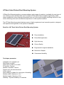
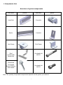
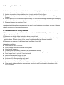
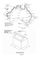
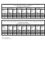
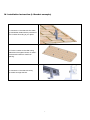
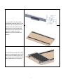
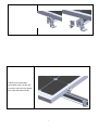
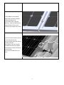
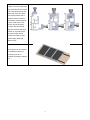
Xiamen Antai New Energy Tech Co.,Ltd.
Installation Manual
Solar Mounting System
(Pitched Roof Solution)
Version 1.0
Office Add: 508#, North Tower, Guangxia Building Huli
Torch Hi-tech Zone, Xiamen, China
Factory Add: Guanshan industrial park Changtai county,
Zhangzhou,China
Tel:86-592-3852509
Fax:86-592-3852618
Email:[email protected]
1
AT Rack Solar Pitched Roof Mounting System
ATRack Roof Mounted solution, accommodating a wide range of modules, is suitable for most type of
roof. With innovative ATRack Rail and G module, ATRack Roof Mount enables significantly faster,
easier installations, which has been developed into one of the most versatile mounting solutions in the
world, delivering time and cost effective experience to solar system installers.
The AT Rack Mounting system features series of highly engineered new innovative product, designed
with experienced engineers to the speed of installation.
Benefits of AT Rack Solar Pitched Roof Mounting System
●
Easy Installation
●
Diversified Application
●
High Accuracy
●
Choice Quality
●
Engineered to highest standards
●
Maximum Lifespan
●
Guaranteed durability
Technique parameter:
Installation site: pitched roof
Roof Slope: up to45°
Wind load: To AS1170.2-2002
PV module: Framed
Module orientation: vertical
Support rail: extruded aluminum
Color: natural
Roof cladding: suitable for most types of cladding
Module widths: Maximum 1.0m
Module lengths: Maximum 2.0m
Warranty: 10years durability on materials
2
I. Components List
Overview of system components
Part name
picture
Part name
Antai Rail
G-module
Splice
L bracket
Inter Clamp
End Clamp
Roof
hook(double
Roman tile)
Hex head bolt
M8*60
Galvanized
Corrugated
Screw 12x65mm
with Gasket
Hex head bolt
M8*20
Note: The quantity of requested components depends on the system you ordered.
3
picture
II. Planning the Module Area
1. Number of modules in the vertical direction × module height (please check also the installation
manual of the manufacturer of the solar panel)
2. Number of module in horizontal direction× (module width+17mm)+32mm
3. Determine the layout and horizontal spacing of the brackets( see ⅢDetermination of Fixing
Centres)
4. Vertical spacing of the brackets is approximately 1/2 to 3/4 module height depending on underlying
roof structure that allows secure fixing of screws as specified.
5. Distance between the modules:17mm
1
Caution: Installations that are exposed to the wind or are located on the edge or corners of the roof
make it necessary to leave smaller spacing.
III. Determination of Fixing Centres
1, Determine the wind region for the installation. Refer to AS1170.2:2002 Figure A1 for wind region A,
B, C, or D within Australia.
2, Determine the height of the installation above ground level
3, Determine the position of the installation on the roof noting that region close to edges have higher
wind loadings. Refer to Figure A2 for area of roofs designated as adjacent to edges.
4, Determine the spacing of rail fixings based on Table A1 and A2
Installation conditions:
z Wind loads to AS1170.2:2002
z Wind average recurrence interval of 500 years
z Wind terrain category 2.
z Shielding and topography multipliers, Ms and Mt taken as unity.
z Racks mounted on roofs of enclosed buildings of nominal rectangular shape.
z Roof slopes from 0° up to 45° from horizontal.
z Maximum solar panel length of 2.0m
z Maximum solar panel width of 1.0m
z Minimum of 2 rails supporting each panel
z Maximum solar panel weight of 15kg/m2
z Roof structure to be checked and certified as suitable for applied rack loads prior to installation
z Solar panels to be certified by manufacturer as able to resist wind loads in accordance with
AS1170.2:2002
4
Figure A1
Figure A2
5
Tiled Roof with roof hook fixed to rafter with minimum of 2 x 12 gauge (5.5mm min diameter, 10 TPI)
screws with 50mm min embedment into timber
(Wind Region to AS1170.2:2002)
Wind Region A
Wind Region B
Wind Region C
Wind Region D
Height
Remote
Adjacent Remote
Adjacent Remote
Adjacent Remote
Adjacent
Above
From
to Roof
From
to Roof
From
to Roof
From
to Roof
Ground(m)
Roof
Edge
Roof
Edge
Roof
Edge
Roof
Edge
Edge
Edge
Edge
Edge
5
2700
2375
2297
1875
1810
1477
1425
N/S
10
2647
2162
2090
1706
1719
1404
N/S
N/S
15
2521
2059
1990
1625
1607
N/S
N/S
N/S
20
2451
2001
1935
1580
1521
N/S
N/S
N/S
Table 1 Tiled Roof
Tin roof with “L” bracket fixed to purlin with minimum of 1 x 12 gauge (5.5mm min diameter, 14 TPI and
10 TPI for fixing to steel and timber respectively) screw through to 1.2mm min BMT steel or 50mm min
embedment into timber
(Wind Region to AS1170.2:2002)
Wind Region A
Wind Region B
Wind Region C
Wind Region D
Height
Remote
Adjacent Remote
Adjacent Remote
Adjacent Remote
Adjacent
Above
From
to Roof
From
to Roof
From
to Roof
From
to Roof
Ground (m) Roof
Edge
Roof
Edge
Roof
Edge
Roof
Edge
Edge
Edge
Edge
Edge
5
2430
1620
1514
1009
940
627
538
N/S
10
2012
1341
1254
836
848
566
N/S
N/S
15
1825
1217
1137
758
741
N/S
N/S
N/S
20
1725
1150
1075
717
664
N/S
N/S
N/S
Table 2 Tin Roof
N/S = not suitable
TPI = threads per inch
6
IV. Installation Instruction (L Bracket example)
1. Connect the L bracket with G-module
by bolt M8X25, determine the positions of
the L-bracket according to your plans.
2. Fix the L bracket to the rafter using
Galvanized Corrugated Screw; fix other L
brackets refer tables for maximum
spacing.
3. Connect the L bracket with rail by
G-module and tight the bolt.
7
4. If you need, to connect multiple
rails together, slide the splices on the
rear side of the pre-assembled rails
halfway to the side. Fasten the first
Allen bolt firmly using the Allen key.
Now slide the next rail segment into
the splice. Tighten the second
M8X25mm bolt .The connection is
finished.
5. Place the solar module on the rails,
slide the end clamp tightly against the
solar module and fasten tightly using
the Allen bolt (recommended torque is
8Nm) Please take note of Figure 9.
8
6. Slide the pre-assembled
inter-module clamp into the rails
from above, place it firmly against
the module and fasten loosely.
9
7. Now slide the next module
against the previously installed
module and tighten the
inter-module clamp using the
Allen key, Take care that the anti
slips protection sits in the rail
channel of the lowest row of rails.
8. Place the last module in the row
on the rails (with the first
row of modules, take care that the
anti-slip protection
sits properly in the rail channel)
and fasten the last inter module
clamp and the module end clamp
using the Allen
Key (recommended torque is 8
Nm).
10
9. For each use of the G
module. You must make sure
that: the thread of the screws
does not project through the
lower side of the G module
(max flush).Position the G
Module in the rail channel
and fasten it loosely with2 to
3 turns of the screw. The
screws can still be freely
moved in the rail channel.
Slide the screw to their final
position in connection with
the inter-module clamp,
module end clamp or roof
hooks/hanger bolts and
fastens firmly.
10. Now first row of modules
are installed, continue to
mounting next row of
modules according to steps 5
to 8.
11
V. Warranty
10 year limited Product Warranty, 5 year limited Finish Warranty
Antai Solar Ltd warrants to the original purchaser (“Purchaser”) of product(s) that it manufactures (“Product”) at the original
installation site that the Product shall be free from defects in material and workmanship for a period of ten (10) years,
except for the anodized finish, which finish shall be free from visible peeling, or cracking or chalking under normal
atmospheric conditions for a period of five (5) years, from the earlier of
1) the date when the installation of the Product is completed, or
2) 30 days after the purchase of the Product by the original Purchaser (“Finish Warranty”).
The Finish Warranty does not apply to any foreign residue deposited on the finish. All installations in corrosive atmospheric
conditions are excluded. The Finish Warranty is VOID if the practices specified by AAMA 609 & 610-02 – “Cleaning and
Maintenance for Architecturally Finished Aluminum” (www.aamanet.org) is not followed by Purchaser. This Warranty does
not cover any damage to the Product that occurs during its shipment, storage, or installation.
This Warranty shall be VOID if installation of the Product is not performed in accordance with Antai’s written installation
instructions, or if the Product has been modified, repaired, or reworked in a manner not previously authorized by Antai IN
WRITING, or if the Product is installed in an environment for which it was not designed. Antai shall not be liable for
consequential, contingent or incidental damages arising out of the use of the Product by Purchaser under any
circumstances.
If within the specified Warranty periods the Product shall be reasonably proven to be defective, then Antai shall repair or
replace the defective Product, or any part thereof, in Antai’s sole discretion. Such repair or replacement shall completely
satisfy and discharge all of Antai’s liability with respect to this limited Warranty. Under no circumstances shall Antai be
liable for special, indirect or consequential damages arising out of or related to use by Purchaser of the Product.
Manufacturers of related items, such as PV modules and flashings, may provide written warranties of their own. Antai’s
limited Warranty covers only its Product, and not any related items.
12


![sg_cover [更新済み]](http://vs1.manualzilla.com/store/data/006609770_2-dab25ea3f992d2bddde1c9c3efbdb6cc-150x150.png)