1
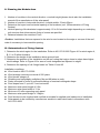
II. Planning the Module Area
1. Number of modules in the vertical direction × module height (please check also the installation
manual of the manufacturer of the solar panel)
2. Number of module in horizontal direction× (module width+17mm)+32mm
3. Determine the layout and horizontal spacing of the brackets( see ⅢDetermination of Fixing
Centres)
4. Vertical spacing of the brackets is approximately 1/2 to 3/4 module height depending on underlying
roof structure that allows secure fixing of screws as specified.
5. Distance between the modules:17mm
1
Caution: Installations that are exposed to the wind or are located on the edge or corners of the roof
make it necessary to leave smaller spacing.
III. Determination of Fixing Centres
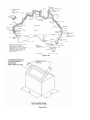
1, Determine the wind region for the installation. Refer to AS1170.2:2002 Figure A1 for wind region A,
B, C, or D within Australia.
2, Determine the height of the installation above ground level
3, Determine the position of the installation on the roof noting that region close to edges have higher
wind loadings. Refer to Figure A2 for area of roofs designated as adjacent to edges.
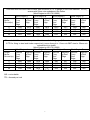
4, Determine the spacing of rail fixings based on Table A1 and A2
Installation conditions:
z Wind loads to AS1170.2:2002
z Wind average recurrence interval of 500 years
z Wind terrain category 2.
z Shielding and topography multipliers, Ms and Mt taken as unity.
z Racks mounted on roofs of enclosed buildings of nominal rectangular shape.
z Roof slopes from 0° up to 45° from horizontal.
z Maximum solar panel length of 2.0m
z Maximum solar panel width of 1.0m
z Minimum of 2 rails supporting each panel
z Maximum solar panel weight of 15kg/m2
z Roof structure to be checked and certified as suitable for applied rack loads prior to installation
z Solar panels to be certified by manufacturer as able to resist wind loads in accordance with
AS1170.2:2002
4