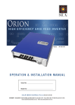
1
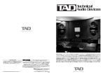
TEMPO
HIGH performance SINEWAVE INVERTER
Models: SEAP-12-500
SEAP-24-700
o p e r ati o n & i n sta l l ati o n m a n u a l
Serial No:
Model No:
S O L A R E N E R G Y A U S T R A L I A P t y L t d ACN 081 639 938
SYDNEY. 4 BEAUMONT RD MT KURING-GAI NSW 2080 TEL 02 - 9457 2277 FAX 02 - 9457 2255
MELBOURNE1/15NICOLE CLOSE BAYSWATER NTH VIC 3153 TEL 03 - 9761 5877 FAX 03 - 9761 7789
Email: [email protected] Web: www.solaraustralia.com.au
Solar Energy Australia
CONTENTS
Introduction and General Information
Warranty
Pre Installation / Electrical Requirements
Installation / AC Wiring / DC Wiring
Start Up Procedure
Controls and Display / Load Sense Feature and Adjustment
Troubleshooting
Technical Data
Mounting Dimensions
2
3
4
5
6
7
8
10
11
Introduction and General Information
Thank you for choosing to purchase another quality inverter from Solar Energy Australia. This product has
been developed to provide you with years of trouble free operation. Your SEA inverter provides True Sinewave
output with power quality and voltage regulation equal to or better than grid electricity.
It is important to us that you get the best out of your inverter, so please take a few minutes to read this manual
carefully, it could save you from frustration. If you have any comments regarding our products or service,
please do not hesitate to contact us to discuss your thoughts.
Remember: As soon as your Solar Energy Australia inverter has been installed please complete and return your
warranty card. This will enable us to efficiently handle any service enquiries you may have, and keep you updated
with any relevant.
Features Include:
• True sinewave at 50Hz
• Total harmonic distortion (THD) <2.0%
• High surge capacity
• Extremely high overall efficiency
• Intelligent overload control
• Short circuit protection
• Quick response stand-by function
• Dynamic battery low voltage control
Page • Designed for harsh climatic conditions
• Manufactured in SMD-technology
• Aluminium base with steel cover
• Integrated DC circuit breaker
• 25mm sq battery cables
• AC & DC EMC attenuation.
• M.E.N Compatible
Doc No SPT-1601B Rev 11/08 Tempo Manual
Solar Energy Australia
IMPORTANT: YOU MUST REGISTER YOUR WARRANTY
SOLAR ENERGY AUSTRALIA WARRANTY Terms and Conditions
Solar Energy Australia considers reliability of your power system/inverter as absolutely critical. Many external influences can
affect the reliability of an inverter. For these reasons we request that you register your warranty within 60 days of purchase.
These terms and conditions do not exclude your rights under the statutory or implied warranty within your state or territory.
Solar Energy Australia warrant this product against defects in material or workmanship, to the original purchaser only for an
initial period of 6 months from date of purchase, when in normal use and service. The warranty period will be extended to a
total of two (2) years when you register your warranty within 60 days of purchase. No warranty will be provided on units,
which have not been paid for in full.
This warranty does not extend to products which have been opened, altered or repaired by persons other than authorised by
Solar Energy Australia or to products which become defective due to acts of God, fire, sabotage, vandalism, contaminated
fluids, negligence or failure to operate, house and maintain the product in accordance with instructions provided in this
manual.
It is extremely important that all installation and operating instructions contained within this manual are strictly adhered
to. Failure to do so may void your warranty. Units, which are to be permanently installed/used within 1km of the coast
should use the marine version of our product. This will help to avoid corrosion problems, which are not covered under the
terms of this warranty.
Solar Energy Australia will repair or replace the defective product in accordance with its best judgement. For service
under warranty, the buyer or installer must contact Solar Energy Australia to obtain appropriate paper work and shipping
instructions before returning the unit. To make a warranty claim you must produce proof of purchase when returning the unit.
Units returned without prior authorisation or warranty registration may be delayed. The buyer will pay all charges incurred
in returning the product to the factory including any charges incurred for the uninstallation or reinstallation of the inverter
and/or its system components. Solar Energy Australia will pay return freight charges, if the product is found to be defective,
within the terms of the warranty. Repair or replacement of any unit does not extend the original warranty terms in any way.
This warranty does not cover repairs made necessary due to the product coming in contact with dirt, abrasives, moisture,
rust, corrosion, varnish or similar, insufficient system maintenance, failure due to poor quality or poor condition batteries,
failure to use an appropriate AC transfer switch or wiring carried out by inappropriately qualified personnel. Solar Energy
Australia will in no way be held responsible for any losses incurred due to the malfunctioning or failure of a product
Suitably qualified personnel must carry out all AC & DC permanent wiring. Failure to do so may void warranty.
To register your warranty you must do the following:
• Return your completed warranty registration card within 60 days of purchase. This can be faxed to +61 (0) 2 9457 2255
or mailed to: Solar Energy Australia Pty Ltd, Unit 2 / 4 Beaumont Road, Mount Kuring-Gai, NSW, 2080.
• Fixed installations must provide a picture of the installation from a distance of 1 metre; household installations must
supply a second picture showing the structure housing the inverter.
• Circuit diagram of installation. This can be obtained from your installer and may be a generic diagram.
Circuit diagrams and pictures can be emailed to [email protected] or posted.
If the above items are not received, they may be requested before work can commence on any faulty units, but please be
aware, Solar Energy Australia is here to help. Help us to help you.
These measures are put in place to ensure you have years of trouble free service from your Solar Energy Australia inverter.
If you have any questions about this warranty please do not hesitate to contact us.
Doc No SPT-1601B Rev 11/08 Tempo Manual
Page Solar Energy Australia
Pre Installation Information
Batteries
Before installing your Sine Wave Inverter, it is important that you have appropriately sized batteries. A battery
that is too small will not allow the inverter to perform to its full specification. Battery performance will vary
between different styles of batteries. For example, a Deep Cycle battery will tolerate deep discharges on a regular
basis much better than a cranking battery, whereas a cranking battery may provide higher voltage when high
battery current is being drawn (eg, when your inverter is starting a motor or Television).
Model
Recommended Minimum
Battery Capacity
Maximum Current Draw of
Inverter
Recommended Battery Fuse
(Motor Start)
SEAP-12-500
100Ah
130Amps DC
63 Amp
SEAP-24-700
130Ah
100Amps DC
50 Amp
Battery Terminology
I = Current
This is the measure of electrical power flowing. This is expressed in Amps. For example, I = 6A means 6 Amps.
Ah = Ampere Hours
This is the amount of energy a battery can store. In theory this means a 200Ah battery could supply 1 Amp
for 200 hours. Alternatively if an appliance draws 2 Amps for 4 hrs then it has used 8 Ah.
CCA = Cold Cranking Amps
This is the maximum amount of current that the battery can supply for a short period of time.
NOTE: Batteries joined in series (+ to -) will increase the voltage but not the Ah. Batteries joined in parallel (+ to +, - to -) will
increase the Ah but not the voltage.
For example: 2 x 12V / 200Ah batteries joined in series = 24V / 200Ah
2 x 12V / 200Ah batteries joined in parallel = 12V / 400Ah
There should be no more than 2 batteries in parallel.
Electrical Requirements
We refer you to Australian Standard AS4509 for further information regarding home power installations.
• DC Input voltage of the inverter must be the same as the battery bank voltage. Please see specification for your model.
High DC input voltage caused by ripple voltage from a poor battery charger, poor condition batteries or loose connections
can cause early failure and is not covered under the terms of your warranty.
• DC cabling must be connected to the correct polarity terminal of the battery bank (Red = Positive, Black = Negative).
• It is not recommended that the DC cables to the inverter be extended. If this is absolutely necessary then you will have to
increase the DC cable size. Consult your supplier/installer for this calculation.
• Do Not Connect 240V AC or any other power source to the 240V output of the inverter as this may cause irreparable
damage to the inverter and can be detected by the repairer.
• If you need to switch from Inverter to Generator or Shore Power it is absolutely critical that no AC power can back feed into
the Inverter. Use a manual changeover switch which has a clear OFF position during changeover. Damaged caused by AC
backfeed can be detected by the repairer and is not covered under warranty.
Page Doc No SPT-1601B Rev 11/08 Tempo Manual
Solar Energy Australia
Installation
WARNING: Please read these instructions thoroughly before commencing installation. Installation should be performed
by a competent professional electrical / renewable energy installer, as dangerous voltage can be present. All relevant
Australian Standards must be strictly followed. A licensed Electrician must carry out all AC wiring.
The following steps should be completed in the order shown in this section.
Unpacking & Mounting
a) Unpack your inverter from its shipping container and inspect the unit for any obvious transit damage. Report any concerns
immediately to your supplier. Please keep original packaging in case it is required for re-transport at a later date.
b) Mount the inverter to a suitable surface, paying close attention to the mounting requirements set out below.
• Select a site that is dry and free of salt or moisture-laden air, dust, exhaust or battery gases and access to any rodents.
The unit can be mounted vertically or horizontally.
• Never mount the inverter directly above the batteries.
• Mount the inverter as close to the batteries as possible, preferably NOT in the same enclosure as gassing batteries can
cause erosion to electronics. Mounting should be on a solid surface capable of withstanding temperatures of 60° C.
• Allow a cooling space of at least 200mm all around the inverter. Placing the inverter in a cupboard or small enclosure
may reduce the available output power. The installation site should not be susceptible to temperatures in excess of
50o C.
AC WIRING
IMPORTANT; All AC wiring must comply with relevant Australian and local standards, and be performed by a licensed
electrician to satisfy warranty requirements and conditions.
Connect active, neutral and earth to a 10 amp 3 pin male AC plug top. Due to the use of a large transformer, galvanic isolation
is provided between the input and output. This means that the Tempo is compatible with M.E.N. installations.
Tips
• Avoid running AC/DC wiring next to other DC wires.
• Avoid running AC/DC wiring near any antenna wiring.
• Avoid running AC/DC wiring near audio equipment.
DC WIRING—VEHICLE
Doc No SPT-1601B Rev 11/08 Tempo Manual
Page Solar Energy Australia
The primary consideration is to ensure that the battery bank voltage matches the DC input voltage rating of the
inverter. The batteries should be located only a short distance from the inverter in order to obtain best results.
A battery fuse MUST be installed to protect all wiring connected to the battery, we suggest the use of a motor
start fuse, see page 4 for recommended size.
Before making any connections, ensure the Tempo’s circuit breaker is in the OFF (down) position. Connect
the inverter DC input cables to the battery terminals via the battery fuse, ensuring the correct polarity ( RED =
positive).
Start-Up Procedure
a) Check battery condition and voltage are within specifications.
b) Ensure the DC circuit breaker is set to the OFF (down) position.
c) Plug in the AC connector, but do not switch ON.
d) Switch DC circuit breaker to the ON (up) position.
e) If all is well the AC status LED will be flashing orange. This indicates all parameters are normal and the unit is in Standby
waiting for an AC load to be switched ON.
f) Switch ON AC.
Page Doc No SPT-1601B Rev 11/08 Tempo Manual
Solar Energy Australia
Controls and Display
Your Tempo inverter has a straightforward multicolour indicator LED (light emitting diode).
AC Status LED
This multicolour LED shows the status of the output as described below.
Colour of LED
Flashing Orange
Inverter is in stand-by waiting for an AC load to be switched ON.
Steady Green
Inverter is operating normally
Steady Red
AC-Output has shutdown due to an AC short circuit or the output has been
overloaded.
Reduce load or check for faulty wiring.
Warning! The inverter restarts automatically after 20 seconds.
Flashing Red
Inverter has shut down due to either Low Battery Volts or Over Temperature.
Warning! The inverter will restart automatically when the fault has cleared.
Load Sense Feature and Adjustment
Your Tempo inverter features a Standby circuit for automatic load sensing, which allows the inverter to remain in Standby
when no AC load is switched ON. Once an AC load is switched ON the inverter will immediately start. This feature conserves
valuable battery energy as the inverter only uses approx 10% of the normal power when in standby (flashing orange). The
amount of AC power required to start the inverter can be adjusted; the procedure for this (adjusting the sensitivity) is outlined
below.
When no AC load is present, the inverter should remain in standby (flashing ORANGE).
Adjusting load sensitivity as follows:
Ensure battery voltage is nominal, that is, 12V or 24 V DC.
• Turn all AC loads OFF, keeping the AC wiring connected. Some loads such as TV’s must be turned OFF at the power point
as they can still represent a small load to the inverter.
• Using a small screwdriver adjust the black plastic trim pot located to the right of the LED. Adjusting this pot clockwise
will make the inverter less sensitive. Turning the pot all the way clockwise will override the standby circuit and keep the
inverter ON all the time, this could be used when you have a very small load that must stay ON at all times. Turning the pot
all the way counter clockwise will turn the inverter OFF.
• Adjust the pot until the LED is steady green, now turn the pot back the opposite way until the LED flashes orange. Allow 10
seconds in between adjustments for stabilisation.
Clockwise = less sensitive, anti clockwise = increased sensitivity.
Note: the trim pot is extremely sensitive.
When the LED flashes ORANGE, the unit is in standby mode.
• Turn on the smallest AC load in the home. The unit should now deliver power, and the AC Status LED should be GREEN.
However, if the LED is ORANGE the sensitivity must be increased.
• Now turn OFF the AC load. The LED should return to flashing ORANGE. If this does not occur, reduce sensitivity.
Doc No SPT-1601B Rev 11/08 Tempo Manual
Page Solar Energy Australia
Troubleshooting
AC Load does not stay ON
Some AC loads may not be large enough to hold the inverter ON. This condition may be recognised by the load
turning off after every eight to ten seconds, then back on again. AC Status LED will also be flashing orange.
There are two possible solutions to this:
• Increase the sensitivity of the inverter by turning the Standby Pot slightly counter clockwise until the LED shows
steady green;
• Increase the amount of AC load on the inverter.
Inverter shuts down due to Over Temperature
Your inverter will safely provide the output power as described in the technical data section in the conditions
specified. If your inverter shuts down and indicates over temperature, it may be that you have exceeded one of
the parameters.
Check for the following:
• Ensure the inverter has adequate ventilation, insufficient ventilation can severely restrict the power output of
your inverter.
• Ensure the true power rating of your appliance (including power factor) does not exceed the rating of your inverter.
Inverter shuts down when trying to start a load
When starting a load such as a motor it may cause the inverter to shut down, if this is the case
• Ensure the battery voltage is within spec when the appliance is trying to start, if not, you may need to increase the size
of your batteries.
• If battery voltage is OK then the inverter may be too small, consult your Solar Energy Australia representative.
Screeching noise on radio when inverter is operating
Your Solar Energy Australia inverter is manufactured to the highest standards for the reduction of EMI( Electro
Magnetic Interference). It is still possible however that in extreme cases, interference may be noticeable in radio’s
or Television sets. Below are some suggestions to try to reduce this noise.
• If possible run a heavy gauge earth wire from battery negative to a moist ground stake, also connect this to the earth
stud on the chassis of the inverter.
• Separate AC and DC wiring.
• Improve signal strength of receiver by improving antenna.
• Reposition inverter as far away from receiver as possible.
Inverter stays shut down for a long time after overload
The inverter is responding to either a severe overload or repeated overloads. Turn the inverters circuit breaker
OFF for 30 seconds and then reconnect. If the cause of the original shutdown is still present, the inverter will
shut down again. Turn off the breaker and reduce load or allow the inverter to cool down before reconnection.
Page Doc No SPT-1601B Rev 11/08 Tempo Manual
Solar Energy Australia
How long will my battery last?
The state of charge of your battery is critical to the performance of your inverter, follow this guide to calculate
how long your battery will last.
Step 1
Take the power rating of your appliance and divide this by 10 (divide by 20 for 24volt systems.) this is the
approximate current the inverter will draw from your battery.
Step 2Take the Ah (Ampere Hour) rating of your battery and divide it by two, this is the conservative amount of useable power in your battery.
Step 3 Now divide the current draw into the useable battery capacity , this is the maximum number of hours you should use this appliance. This equation presumes that no other charging has taken place.
Example: A 67 watt TV running on a 100Ah battery.
Current draw = 67/10 = 6.7Amps DC
Useable battery capacity = 100/2 = 50Ah
Time = 50/6.7 = 7.4 hrs
How can I tell if my Inverter is in Standby if I am in the house?
It is important to keep your inverter in standby whenever no power is being used. A power point with a neon
indicator or a child’s night light will mimic the output of the inverter. eg, these will flash when the inverter is
in standby. This feature will save unnecessary battery drain.
Doc No SPT-1601B Rev 11/08 Tempo Manual
Page Solar Energy Australia
Technical Data @ 30°C 1.0 PF
SEAP-12-500
SEAP-24-700
12V
24V
DC Low voltage cutout
9.0-10.5V
18-21V
DC High voltage cutout
16V
32V
AC Output power @ 30°C Continuous
500watts
700watts
30 minutes
560watts
900watts
5 minutes
1100watts
1300watts
5 seconds
1500watts
2100watts
DC Input Battery Voltage
AC Output Voltage
230v +/ 2%
AC Output Frequency
50Hz +/- .5%
Total Harmonic Distortion
Maximum AC output current
3%
6A AC
9A AC
4A
6A
40mA
25mA
0.45A DC
0.40A DC
DC Current draw at full continuous load
50A DC
35A DC
DC Current draw maximum
130A DC
85A DC
Efficiency @ 10% of load
88%
90%
Efficiency @ 100% of load
80%
82%
Efficiency @ 90% of load
87%
88%
Peak Efficiency
91%
94%
Suggested AC output Circuit Breaker
DC Current draw in Standby
DC Current draw no load, AC ON
Stand-by Adjustment
3-40watts Logarithmic
AC Output Connection
Double pole switch with 10A GPO
DC Input Connection
1.4metres, 25mm² flexible cables with 8mm lugs
Fan Control
ON @ 55° C, OFF @ 45° C, or ON if power exceeds 400 watts
Operating Range
-25°C to +50°C
Temperature Derating above 30o C
Safety Standards
-11.0 W / oC
AS3000 Safety
Radio Interference Standard
AS/NZS2064-1997
Warranty
Weight Packed
Dimensions
Page 10
AS.NZS61558-1.2000 TXF
2 years
8.0kg
9.0kg
275mm x 185 x 97mm
Doc No SPT-1601B Rev 11/08 Tempo Manual
Solar Energy Australia
Mounting Dimensions
Doc No SPT-1601B Rev 11/08 Tempo Manual
Page 11
Solar Energy Australia
Solar Energy Australia PTY LTD
Sydney
4 Beaumont Road
Mt Kuring-Gai, NSW 2080
Tel: (02) 9457 2277 Fax: (02) 9457 2255
Melbourne
1 / 15 Nicole Close
North Bayswater VIC 3 153
Tel: (03) 9761 5877 Fax: (03) 9761 7789
Email: [email protected]
Website: www. solaraustralia. com. au
Page 12
Doc No SPT-1601B Rev 11/08 Tempo Manual