1
Installation Manual
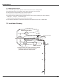
7.3 Install Indoor Unit
7.3.1 Installation of Mounting Plate
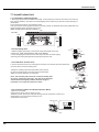
1. Mounting plate should be installed horizontally. As the water tray's outlet for the indoor unit is two-way
type, during installation, the indoor unit should slightly slant to water tray's outlet for smooth drainage of
condensate.
2.Fix the mounting plate on the wall with screws.
3.Be sure that the mounting plate has been fixed firmly enough to withstand about 60 kg. Meanwhile, the
weight should be evenly shared by each screw.
(Note: the wall hole for 18K unit is Φ 65mm.)
Wall
09K UNIT:
Wall
Wall
Above
150 from
the wall
Above
150 from
the wall
Φ55
Φ55
Left
Right
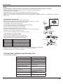
7.3.2 Drill Piping Hole
Indoor
Outdoor
Wall pipe
1. Make the piping hole (Ф55) in the wall at a slight downward slant to the
outdoor side. (Note: the wall hole for 18K unit is Φ 65mm.)
2. Insert the piping-hole sleeve into the hole to prevent the connection piping
and wiring from being damaged when passing through the hole.
Seal pad
Φ55
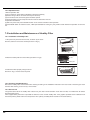
7.3.3 Installation of Drain Hose
1.Connect the drain hose to the outlet pipe of the indoor unit. Bind the joint with rubber belt.
2.Put the drain hose into insulating tube.
outlet pipe of
indoor unit
drain hose
outlet pipe of
indoor unit
3.Wrap the insulating tube with wide rubber belt to prevent
the shift of insulating tube. Slant the drain hose downward
slightly for smooth drainage of condensate.
rubber belt
outlet pipe of
indoor unit
drain hose
rubber belt insulating tube
Note: The insulating tube should be connected reliably with
the sleeve outside the outlet pipe. The drain hose should be
slanted downward slightly, without distortion, bulge or
fluctuation. Do not put the outlet in the water.
rubber belt
outlet pipe of
indoor unit
connected
bulge
Flooded
7.3.4 Connecting Indoor and Outdoor Electric Wires
1.Open the front panel.
2.Remove the wiring cover as shown in Fig 6.
3.Make the power connection cord pass through the hole at the back of indoor unit.
4.Reinstall the cord anchorage and wiring cover.
5.Reinstall the front panel.
Wiring Cover
N(1)
blue
2
black brown
3
yellowgreen
outdoor unit connection
Fig.6
20
insulating tube
distortion