1
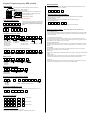
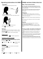
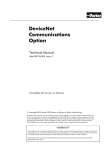
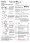
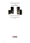
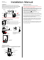
Installation Manual
605A & AK
V2 (1200 keypad)
Installation
1) Before you install this equipment, please read this full manual.
2) Before screwing the camera unit to a wall or pillar, quickly connect
12v power to the camera unit, power up the monitor unit, and RANGE
TEST the system to check if it works at your required distance!
3) As per Fig 1, plan the installation of the system.
Fig.1.
Up to
200m
House or
reception
area
Antennas
Mount at
eye level
For longer range
applications, locate
monitor handset near a
window at front of
property.
Keep antennas high!
Entrance
Pillar
1.2m
minimum
Note: Wood and glass only reduce signal strength by 10-20%. Masonry will
reduce signal strength by 20-50% per wall. Metal can totally block signals.
Installing the Speech Panel
Security Screws.
1) Unscrew both security screws, and the front door will hinge
downwards.
2) Drill a 20mm hole for the antenna cables and power wires.
3) Fit the intercom in place, lining up the rear access hole with the drilled
hole for the cables.
4) Use at least 10mm diameter, 50mm deep fixings to secure the
intercom to the wall. This will prevent it from being removed.
Video
antenna
connection
Wiring
Audio antenna
Audio
antenna
connection
Code
button
Directional Video
antenna dish
+ 12v
- dc in
N/C COM
Note: Be sure to connect the correct
antenna to the matching antenna port
on the door station.
Do NOT cut antenna leads or attempt
to extend them.
Relay output volt
N/O free 4 sec pulse
Tamper
N/C
N/O
COM
N/C
OUT3
INT Lock
O/P1 inhib
Sense
(-)GND
DU out
K or A
Keypad Connections
(ABK model)
+ egress
N/O
COM
N/C
N/O
COM
N/C
12-24v
dc
OUT1 OUT2
Handset Functions
The handset comes with a Lithium Ion high quality mobile phone battery.
It is recommended to charge it for 8 hours before testing, to maximise
battery life.
Microphone
Video Screen
Monitor button
Door / Gate Release button
D Pad
On/Off
OK
Vibrate Switch
Code Button
Speaker
Charging base
Charging LED
Operation & Testing
1) Power up the door station and switch on the handset.
NOTE: You may need to wait up to 1 minute until the handset detects
the door station before you can test operation.
2) Press the call button on the door station. The handset should ring. If
it does not, try moving the handset to a different location and try again.
3) Check the screen which should show video images.
4) Answer the call, by pressing the OK button. You should be able to
hear and speak to the intercom from the handset.
5) While on the call, press
to adjust the volume.
5) Press the door release button to activate the door or gates.
6) Press the OK button to end the call.
You will note that the video monitoring is designed to stay active for a
while even after the call has ended and the audio channels are closed.
Note: The handset should be held within 10-20cm of the person
speaking to achieve best volume performance. Speak into the top part
of the handset where the microphone is located.
If the handset is not answered within 40 seconds, the visitor will be
played a voicemail greeting by the door station, and they can leave a
voice message. In this case, after 1 minute a message symbol will
appear on the handset screen.
Note: The gates or door can be released from the handset even when
there is not a call active. Press and HOLD the release button for at
least 3 seconds to activate.
Keypad Programming (only ABK models)
Restoring defaults
LED indicators
While in programming mode, enter the following to delete all codes and settings apart from the
Master code.. (this can take up to 2.5 minutes)...
ON when incorrect codes entered and outputs are locked out.
GREEN when output 1 activated.
RED when output 2 activated.
9
1
2
3
FAST FLASHING – Wrong code entered / error.
4
5
6
SLOW FLASHING - in normal standby mode.
7
8
9
ON in programming mode.
*
0
#
ON when relay 3 activated.
Enter Programming mode
0
0
0
*
The unit is now in programming mode. Amber LED
will remain ON. 0000 is default programmers code.
Note: Pressing ** again will exit programming
mode.
*
9
9
#
When the master code is forgotten….
1) Wire a push button (or replicate with wire link) across the EG IN terminal and (-)GND.
2) Switch off power for 1 minute.
3) Switch ON power.
4) during the first 60 seconds, press the EG button once to enable the function.
5) Enter the following code..
Note: Programming can only begin 60 seconds after power on.
0
9
8
0
8
0
*
*
The keypad should now be in programming mode, ready to accept new data.
Enter new programmers code
0
1
?
Location
?
?
?
#
4-8 digit code
Additional keypad information – Note: These features are not commonly used.
Validate
EG IN (EGRESS INPUT)
Connect a push button between this terminal and (-)GND. When Egress button is pressed, output 1
will be activated for the programmed delay. Egress button is usually located inside a building and
used as a push to exit.
Record or Delete user codes
1
0
2
10= relay 1 codes
(1000 available)
20= relay 2 codes
(100 available)
30= relay 3 codes
(100 available)
0
0
0
?
?
Memory locations
000-999 for relay 1
001-100 for relay 2
001-100 for relay 3
2= add code
5= delete code
?
?
#
Pin code 4-8 digits
Validate
0
2
Group 2
0
Add code
3
1
5
Location 31
5
5
5
Pin code 5555
#
Interlock Output
NPN transistor output, open collector, max power 24v dc, 100mA sink. Used to operate a door in
conjunction with another keypad, or prevent two doors being opened at the same time.
?
10=relay1
20=relay2
30=relay3
5
?
Delete code
?
?
#
ID location to be deleted
Tamper N/C
Normally closed tamper switch. This can be used in conjunction with a tamper switch on a box or
enclosure to prevent tampering. This can be connected to an alarm system.
Validate
Delete all codes in a group
?
?
0
10=relay1 group
20=relay2 group
30=relay3 group
9
9
9
#
Super delete code
Validate
Programming Relay output times & modes
?
?
0
1
or
-
9
9
9
9
0 = start / stop toggle mode (latching)
1-99999 = seconds momentary operation
51=relay1
52=relay2
53=relay3
9
#
Validate
Programming SUPER user code
Super user code is an optional feature which allows the same code to operate outputs 1, 2 or 3.
0
O/P 1 Inhibit
Normally open. When closed, this disables all codes for relay group 1 except super user and duress
codes.
Validate
Delete a code
?
DU OUT (DURESS OUTPUT)
An NPN transistor open collector output. It switches to (-) ground after the Duress Code is entered.
Use it to trigger an alarm zone, or turn on a buzzer to notify a guard. Ic max: 100mA sink. Vc max:
24VDC
DOOR SENSE
N/C connected to (-)GND, to be connected to a normally closed door contact. It can be used to
generate a door open alarm or door forced open alarm.
Example: Add user 31 to have access code 5555 operating relay 2….
2
K or A. (KEYPAD ACTIVE OUTPUT)
An NPN transistor open collector output. It switches to (-) ground for 10 seconds on each key
touching. This can be used to turn on lights, CCTV camera, or buzzer to notify a guard. The rating
of this output is: Ic max: 100mA sink, Vc max: 24VDC
2
?
Location
?
?
?
#
4-8 digit code
Validate
Using super user code
?
?
?
?
#
1
Activate output 1
?
?
?
?
#
2
Activate output 2
?
?
?
?
#
3
Activate output 3
Using standard user code
To use standard code, simply enter the 4 digit code.
Note: Remember to exit programming mode with ** before testing user codes.
Operating Instructions for 605A & 605AK wireless Video Intercom
Operation
Gate / Door release button
1) When handset rings, visually identify the visitor.
If you wish to open a gate or door, even when there is no one
there, for example, for a vehicle leaving premises, then the gate
or door release button can be pressed for 3 seconds to activate
the door/gate release.
40-80c
m
Please use this function with extreme caution with electric gate
systems. Please ensure this handset is kept out of reach of
small children.
Charging
2) Press OK to answer the call.
3) Speak clearly into the TOP part of the handset as shown.
The handset is capable of holding charge for more than 24
hours, however it is recommended that it is left on the charging
cradle at least for night time.
Using the vibrate function will shorten battery life depending on
usage.
10cm
Do not use any other charging device other than that supplied
with the system.
Service
4) During a call, press
5) Press
to adjust volume.
to open the gate or door.
Coding another handset to the System
Settings
The following settings can be changed in the system. To make
these changes, you must put the system in monitoring mode by
pressing the
key.
Once the video image appears, then the following apply...
Ringing volume
In monitor mode, press
to adjust the ringing volume.
Listening to Voicemail messages
To listen to voicemail, press OK to play. If there are more than 1
message, press
and
to select the message required and
press OK to play.
= Pause / Exit
= Continue
= Delete, long press
= delete all.
Enter Menu
Press and hold
key for 3 seconds to enter the Menu.
You can navigate options for…
Brightness
Language
Message
Bell
Colour
Press
to scroll
Should you have any operational problems, contact your
professional security installer firstly.
Do not open the unit or attempt to make any repairs. Please
contact the manufacturer or merchant for replacement parts or
spares.
Press
to exit
Press OK to select
To add an extra handset to the system, follow the sequence
below..
1) Press and HOLD the code button on the door station for 3
seconds, until the LED’s on the bottom of the board start to
flash.
2) Press and hold the Code button on the new handset ignoring
the first short tone, until you hear a confirmation tone (“Di-DoDo”). This may take up to 10 seconds.
3) Once the door station lights stop flashing, then you can test
the system by pressing the call button on the door station. The
new handset should ring. If not, repeat the process from the top.