1
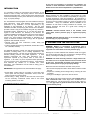
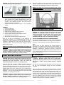
The minimum spacing between tanks must be equal to twice the
width of a single deadman. One deadman may be used between
two tanks if it is double in width. Provide a separate anchor point
for each hold down strap.
Deadmen are to be butted together where multiple sections are
used. Place A to A and AA to AA (Marked on Deadmen).
ANCHOR SLAB
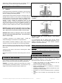
An anchor slab is a reinforced concrete base. The total length of
the slab is 300mm greater than the overall length of the tank. The
minimum slab thickness is 200mm. The width of the slab depends
on the tank diameter. Refer to Table 6-1 for specific dimensions.
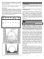
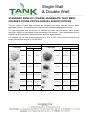
Refer to Table 6-2 and Figure 6-2 for anchor point dimensions.
Provide a separate anchor point for each holddown strap. When
using a concrete base slab, allow sufficient depth in the excavation
for 300mm of bedding material below the tank.
TABLE 6-2
TANK
DIA.
DIM
“A”
DIM
“B”
DIM
“C”
DIM “E”
MIN / MAX
DIM
“D”
1470
430
130
650
810
960
2850
2438
1143
838
381
1120
1370
4597
2600
X
Y
Z
1
2
3
3275
990
690
947
1862
2012
7010
FIGURE 6-2
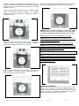
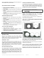
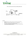
NOTE: When fastening wire cable, use a minimum of three clamps
on each joint. Use shackle type or chair type clamps as appropriate
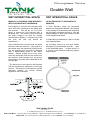
HOLDDOWN STRAPS:
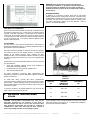
Tank Solutions Hold Down Straps should be used when a tank is to
be anchored. The location of the straps are marked on the tank by
the ►◄ symbols. An installation guide is provided as a separate
booklet.
CAUTION: Place the straps only in the locations designated by
the arrow symbols ►◄.
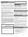
A measurement must be taken of the tank diameter before the
straps are tightened (Measurement A on the Installation Checklist Refer to Section 14 for methodology). To evenly distribute
buoyancy loads tighten all hold down straps uniformly but cause no
deflection of the tank. An intermediate (intermediate 1)
measurement should be taken of the tank diameter after the straps
have been tightened. This should be compared with measurement
A to ensure tank is inside the deflection allowance (see Deflection
Allowance table on Installation Checklist and Section 14 for
methodology)
NOTE: All exposed metal on the hold down straps, turnbuckles
and/or threaded rod must be coated or galvanised to prevent
corrosion.
7. DRY HOLE INSTALLATION
CAUTION: Tank Solutions recommends that every site be
thoroughly evaluated for the potential to trap water or
otherwise subject the tank to a rise in the local water table.
Tank Solutions recommends that all tanks be anchored and
ballasted in installations in which water could rise in the hole.
Failure to anchor and ballast the tank in a wet hole or one that
can hold water may damage the tank or surrounding property.
Following installation of anchors, prepare a smooth level bed,
300mm thick (to top of anchors), of approved backfill material.
Place the tank or tanks onto the bed. Do not set Tank Solutions
tanks directly onto a concrete slab or on timbers, cradles or directly
onto the hole bottom. Levelling: As the tank is being placed, set the
tank pitch as shown on the site plans. Tank Solutions does not
require that a tank be pitched. All pitch is determined by the tank
owner’s specification. If a double wall tank is pitched, the monitor
should be at the low end. Use the tops of the ribs to establish
longitudinal level. Establish lateral level by placing the level across
the top of a fitting, a manway or a collar. When the tank is placed,
take the first internal diameter reading (Deflection reading “A” on
the checklist). See Section 14 for instructions on taking deflection
readings. Before backfilling, do a visual inspection on the tank, if no
damage is found, note this on the Installation Checklist and
continue to follow these instructions. If damage is found, contact
Tank Solutions.
BACKFILLING
Use only approved backfill material (See Section 3). Do not mix
approved material with sand or native soil. Do not use native soil
as backfill material. All excavated native soil must be replaced with
approved material. Place one 300mm lift of material evenly around
the tank. From the hole side or the top of an adjacent tank, work
the material by hand completely beneath the tank body and domes
to provide full support. Use a probe long enough to reach beneath
the tank and push the backfill in place. Repeat this setup with a
second 300mm lift. After the second lift of material has been
placed and probed, the backfill can be brought to the top of the tank
without further hand work.
Tank Solutions Fibreglass Single & Double Wall Tank Installation Manual Form F 938
Revision A
Page 6 of 14