1
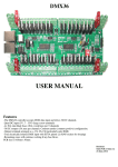
AAHMEGA60
USER
MANUAL
Features
-The AHMEGA60 controller accepts DMX data input and drives 60 DC channels.
-Quad DC input (5V - 40V) (large screw terminals)
-4x 30A mini blade fuses (30A overall max per 15 channels)
-Adjustable output voltage per zone. Pulse width modulated output voltage emulation
-60 DC outputs (5A max per channel). Common anode (common positive) configuration.
-Output terminals arranged as V+, Ch, Ch, Ch (particularly suits RGB)
-True electrically isolated DMX input (2x RJ45 sockets for looping)
-ESTA or LOR network wiring configuration can be selected via on board jumpers adjacent to RJ45 DMX sockets
-Remaining zones will continue working if any fuse blows
PCB size is 238mm x 115mm
Revision 3
Suits PCB revision 1.2
2-November-2012
INDEX
CONNECTIONS . . . . . . . . . . . . . . . . . . . . . . . . . . . . . . . . . . . . . . . . . . . . . . . . . . . . . . . . . . . . . . . . . . -3Dmx Data . . . . . . . . . . . . . . . . . . . . . . . . . . . . . . . . . . . . . . . . . . . . . . . . . . . . . . . . . . . . . . . . . . . -3DC Power Input . . . . . . . . . . . . . . . . . . . . . . . . . . . . . . . . . . . . . . . . . . . . . . . . . . . . . . . . . . . . . . -3Dimmer Outputs . . . . . . . . . . . . . . . . . . . . . . . . . . . . . . . . . . . . . . . . . . . . . . . . . . . . . . . . . . . . . . -3USB Connector . . . . . . . . . . . . . . . . . . . . . . . . . . . . . . . . . . . . . . . . . . . . . . . . . . . . . . . . . . . . . . -4ICSP Connector . . . . . . . . . . . . . . . . . . . . . . . . . . . . . . . . . . . . . . . . . . . . . . . . . . . . . . . . . . . . . . -4-
USING THE AAHMega60 . . . . . . . . . . . . . . . . . . . . . . . . . . . . . . . . . . . . . . . . . . . . . . . . . . . . . . . . . . -4Status Leds . . . . . . . . . . . . . . . . . . . . . . . . . . . . . . . . . . . . . . . . . . . . . . . . . . . . . . . . . . . . . . . . . . -4Start Channel . . . . . . . . . . . . . . . . . . . . . . . . . . . . . . . . . . . . . . . . . . . . . . . . . . . . . . . . . . . . . . . . -4Test Mode . . . . . . . . . . . . . . . . . . . . . . . . . . . . . . . . . . . . . . . . . . . . . . . . . . . . . . . . . . . . . . . . . . -4Zone Volts . . . . . . . . . . . . . . . . . . . . . . . . . . . . . . . . . . . . . . . . . . . . . . . . . . . . . . . . . . . . . . . . . . -4Mode Jumpers . . . . . . . . . . . . . . . . . . . . . . . . . . . . . . . . . . . . . . . . . . . . . . . . . . . . . . . . . . . . . . . -4Dmx start address table . . . . . . . . . . . . . . . . . . . . . . . . . . . . . . . . . . . . . . . . . . . . . . . . . . . . . . . . -5-
CONNECTION EXAMPLES . . . . . . . . . . . . . . . . . . . . . . . . . . . . . . . . . . . . . . . . . . . . . . . . . . . . . . . . -6-
WARRANTY . . . . . . . . . . . . . . . . . . . . . . . . . . . . . . . . . . . . . . . . . . . . . . . . . . . . . . . . . . . . . . . . . . . . -7-
ENQUIRIES/REPAIRS . . . . . . . . . . . . . . . . . . . . . . . . . . . . . . . . . . . . . . . . . . . . . . . . . . . . . . . . . . . . -7-
Connections
Dmx Data
There are 2 RJ45 dmx sockets on the board. These are
designed for loop in and loop out.
If the AAHMega60 is the last dmx device on the dmx
cable then the signal should be terminated with the
termination jumper. Basically if only 1 cable is plugged in
to the dmx sockets then the termination jumper should be
installed. If both sockets are used then the termination
jumper should be left off.
There are 2 sets of jumpers adjacent to the dmx sockets.
These allow for connection to either ESTA or Light-ORama (LOR) networks. If the next device connected to a
given socket is wired according to the ESTA standard then
the 3 jumpers would be installed in the ESTA network position. If the next device is a LOR device (USB dongle,
CTB16PC etc) then the 3 jumpers would be installed in the LOR position. The relative positions for the 2 networks is
marked on the pcb.
DC Power Input
The 4 large 2 way green connectors are the DC inputs from your power supply. Each of the 4 zones of 15channels can
use a separate power supply or you can feed them all from one
common power supply. Separate wiring (back to the power
supply) for each of the zones is recommended to minimise
voltage drop. The +V terminals are positive and the -V
terminals are negative. Any DC voltage in the range of 5V to
40V can be used. The negative (-V) terminals are commoned
between the 4 zones so this must be taken into account when
wiring up to the power supply/supplies. Each of the 4 zones has
a standard ATX (automotive) fuse adjacent to the power
terminals. The AAHMega60 comes supplied with 10A fuses
fitted. Fuses up to 30A can be used. It is recommended
changing the fuse to the closest size for the total current that the
zone will be supplying.
It is recommended that the dmx cables not be connected when
changing from LOR to ESTA as an accidental short circuit may
damage the dmx transmitter.
Dimmer Outputs
There are 60 channel outputs; 30 per side with each side divided into 2 zones. Each side can be run at the same, or a
different supply voltage. Any DC voltage in the range of 5V to 40V can be used for each of the banks.
The maximum load per channel is 5 Amps, but remember that the overall limit per bank/zone of 15 outputs is 30 Amps.
This means that you can't turn on all 15 outputs of a zone with the maximum load. In reality, this should not be a problem
as most loads will be less than 2 Amps.
There are 60 dimmer outputs which are in banks (zones) of 15 with each zone of 15 fused separately. Each group of
3 outputs is grouped into 4 terminals. These are the 3 outputs and a common positive. RGB lights with a single common
anode should have the common wire connected to the terminal +V (the 4 banks have common +ve terminals +V1, +V2,
+V3 and +V4) and the red, green and blue wires to channels 1,2,3 (or 4,5,6 etc). The order and specific channels is
actually dependant on what is configured in your sequencing software. For lights that have single colours (or single
channels) per pair of wires then 1 wire gets connected to the +V and 1 gets connected to the channel output. For led lights
which require the polarity to be around the right way then the anode (positive) gets connected to +V and the cathode
(negative) goes to the channel. For lights that do not have three channels commoned then 3 wires will be joined and fitted
to the +V for the 3 channels.
See the Connection Examples section for the various methods of connecting lights.
-3-
USB Connector
A USB connector is provided for program (firmware) updates. This currently has not been enabled in the firmware.
ICSP Connector
A ICSP (in circuit serial programming) connector is provided for initial programming of the microprocessor and for program
(firmware) updates.
USING THE AAHMega60
Status Leds
There are 3 small LEDs near the centre of the PCB adjacent to the micro.
Red led-Power, Blue led-Mode, Green led-Data
-Red led
5V power
-(MODE) Blue led flashing slowly (1Hz ).
(DATA)
-(MODE) Blue led flashing 10Hz.
(DATA)
-(MODE) Blue led on solid.
(DATA)
Green led off. Test mode
Green led off.
Address setting error
Green led flashing 10 Hz. Normal run mode. Dmx packets being
received
-(MODE) Blue led on solid.
(DATA)
Green led flashing at 1Hz. Incomplete dmx packets being
received. At least the first dmx packet is received but there is a
problem with the stream before all 60 channels have their data.
All outputs will be turned off.
This error has been disabled on firmware version 1.2
-(MODE) Blue led on solid.
(DATA)
Green led off. No dmx data
Test mode takes precedence over normal running so errors/status message other than test mode won’t be displayed if in test mode.
Start Channel
The start channel is set via 9 dipswitches. The channel is set in binary by turning on the relevant
switches. DMX addresses can be anywhere between 1 and 512. The address of the
AAHMega60 can be anywhere in the range of 1 to 453 (a start address of 453 uses the
addresses from 453 to the maximum 512). If the address is set outside of this range an error is
indicated via the 2 status leds. See Status Leds. The start channel can be changed at any time.
The start address can be calculated by adding up the totals for the switches that are on. For
example 64 + 16 + 1 would give a start address of 81. A table is provided later in the manual
that lists the dmx start addresses.
Test Mode
There is a switch on the same bank of switches which places the control into a test mode. In this mode a test program runs and all
60 outputs are cycled through. This mode allows for soak testing of lights without the need for a source of dmx data. The control
will cycle through 12 modes of testing from 1 led on at a time, through all reds on, all greens etc. The mode jumpers will change
the test mode in later firmware revisions.
Zone Volts
Each of the 4 zones on the pcb has a 4 way bank of jumpers that allow the apparent output voltage
for that zone to be altered. With this feature a common power supply for the entire board can power
up to 4 different voltages. The microprocessor measures the input voltage of the zone and adjusts
the output so that it matches what is set on the jumpers. The jumper settings are 5V, 12V, 24V, 32V
and when no jumper is installed the output voltage is the same as the input voltage. The peak voltage
on the output is the same as the input voltage so any lights with electronics in them (like ACL
strobes) MUST NOT be used on other than 100% (usually with 5V supply) as the electronics within
them are not rated to high voltages.
The output voltage jumpers can be changed at any time but due to the risk to the lights of having too high an output voltage
it is recommended to either set the jumpers while the unit is powered down or while the lights are turned off.
Note:- It isn’t actually 5V DC (12V, 24V or 32V) but is actually a pulse width modulated output that have an average or RMS
output voltage of 5V (12V, 24V or 32V). The output voltage cannot be increased and if the jumpered voltage is set to higher than
the supply voltage then the control outputs the supply voltage.
Mode Jumpers
There is a jumper bank on the pcb with 4 possible jumper positions. These jumpers are for possible further firmware features for
the pcb. These features include changing test modes.
-4-
Dmx start address table for AAHMega60. Switches are from left to right (on Dipswitch they are labelled as 2 to 10, on PCB they are marked 256, 128 ....... 1
in binary address sequence). Zeroes indicate the switch is off (down). Ones indicate the switch is on (up). First column is the start address and the second column
is the 9 address switches.
1
2
3
4
5
6
7
8
9
10
11
12
13
14
15
16
17
18
19
20
21
22
23
24
25
26
27
28
29
30
31
32
33
34
35
36
37
38
39
40
41
42
43
44
45
46
47
48
49
50
51
52
53
54
55
56
57
58
59
60
61
62
63
64
000000001
000000010
000000011
000000100
000000101
000000110
000000111
000001000
000001001
000001010
000001011
000001100
000001101
000001110
000001111
000010000
000010001
000010010
000010011
000010100
000010101
000010110
000010111
000011000
000011001
000011010
000011011
000011100
000011101
000011110
000011111
000100000
000100001
000100010
000100011
000100100
000100101
000100110
000100111
000101000
000101001
000101010
000101011
000101100
000101101
000101110
000101111
000110000
000110001
000110010
000110011
000110100
000110101
000110110
000110111
000111000
000111001
000111010
000111011
000111100
000111101
000111110
000111111
001000000
65
66
67
68
69
70
71
72
73
74
75
76
77
78
79
80
81
82
83
84
85
86
87
88
89
90
91
92
93
94
95
96
97
98
99
100
101
102
103
104
105
106
107
108
109
110
111
112
113
114
115
116
117
118
119
120
121
122
123
124
125
126
127
128
001000001
001000010
001000011
001000100
001000101
001000110
001000111
001001000
001001001
001001010
001001011
001001100
001001101
001001110
001001111
001010000
001010001
001010010
001010011
001010100
001010101
001010110
001010111
001011000
001011001
001011010
001011011
001011100
001011101
001011110
001011111
001100000
001100001
001100010
001100011
001100100
001100101
001100110
001100111
001101000
001101001
001101010
001101011
001101100
001101101
001101110
001101111
001110000
001110001
001110010
001110011
001110100
001110101
001110110
001110111
001111000
001111001
001111010
001111011
001111100
001111101
001111110
001111111
010000000
129
130
131
132
133
134
135
136
137
138
139
140
141
142
143
144
145
146
147
148
149
150
151
152
153
154
155
156
157
158
159
160
161
162
163
164
165
166
167
168
169
170
171
172
173
174
175
176
177
178
179
180
181
182
183
184
185
186
187
188
189
190
191
192
010000001
010000010
010000011
010000100
010000101
010000110
010000111
010001000
010001001
010001010
010001011
010001100
010001101
010001110
010001111
010010000
010010001
010010010
010010011
010010100
010010101
010010110
010010111
010011000
010011001
010011010
010011011
010011100
010011101
010011110
010011111
010100000
010100001
010100010
010100011
010100100
010100101
010100110
010100111
010101000
010101001
010101010
010101011
010101100
010101101
010101110
010101111
010110000
010110001
010110010
010110011
010110100
010110101
010110110
010110111
010111000
010111001
010111010
010111011
010111100
010111101
010111110
010111111
011000000
193
194
195
196
197
198
199
200
201
202
203
204
205
206
207
208
209
210
211
212
213
214
215
216
217
218
219
220
221
222
223
224
225
226
227
228
229
230
231
232
233
234
235
236
237
238
239
240
241
242
243
244
245
246
247
248
249
250
251
252
253
254
255
256
011000001
011000010
011000011
011000100
011000101
011000110
011000111
011001000
011001001
011001010
011001011
011001100
011001101
011001110
011001111
011010000
011010001
011010010
011010011
011010100
011010101
011010110
011010111
011011000
011011001
011011010
011011011
011011100
011011101
011011110
011011111
011100000
011100001
011100010
011100011
011100100
011100101
011100110
011100111
011101000
011101001
011101010
011101011
011101100
011101101
011101110
011101111
011110000
011110001
011110010
011110011
011110100
011110101
011110110
011110111
011111000
011111001
011111010
011111011
011111100
011111101
011111110
011111111
100000000
257
258
259
260
261
262
263
264
265
266
267
268
269
270
271
272
273
274
275
276
277
278
279
280
281
282
283
284
285
286
287
288
289
290
291
292
293
294
295
296
297
298
299
300
301
302
303
304
305
306
307
308
309
310
311
312
313
314
315
316
317
318
319
320
100000001
100000010
100000011
100000100
100000101
100000110
100000111
100001000
100001001
100001010
100001011
100001100
100001101
100001110
100001111
100010000
100010001
100010010
100010011
100010100
100010101
100010110
100010111
100011000
100011001
100011010
100011011
100011100
100011101
100011110
100011111
100100000
100100001
100100010
100100011
100100100
100100101
100100110
100100111
100101000
100101001
100101010
100101011
100101100
100101101
100101110
100101111
100110000
100110001
100110010
100110011
100110100
100110101
100110110
100110111
100111000
100111001
100111010
100111011
100111100
100111101
100111110
100111111
101000000
321
322
323
324
325
326
327
328
329
330
331
332
333
334
335
336
337
338
339
340
341
342
343
344
345
346
347
348
349
350
351
352
353
354
355
356
357
358
359
360
361
362
363
364
365
366
367
368
369
370
371
372
373
374
375
376
377
378
379
380
381
382
383
384
101000001
101000010
101000011
101000100
101000101
101000110
101000111
101001000
101001001
101001010
101001011
101001100
101001101
101001110
101001111
101010000
101010001
101010010
101010011
101010100
101010101
101010110
101010111
101011000
101011001
101011010
101011011
101011100
101011101
101011110
101011111
101100000
101100001
101100010
101100011
101100100
101100101
101100110
101100111
101101000
101101001
101101010
101101011
101101100
101101101
101101110
101101111
101110000
101110001
101110010
101110011
101110100
101110101
101110110
101110111
101111000
101111001
101111010
101111011
101111100
101111101
101111110
101111111
110000000
385
386
387
388
389
390
391
392
393
394
395
396
397
398
399
400
401
402
403
404
405
406
407
408
409
410
411
412
413
414
415
416
417
418
419
420
421
422
423
424
425
426
427
428
429
430
431
432
433
434
435
436
437
438
439
440
441
442
443
444
445
446
447
448
110000001
110000010
110000011
110000100
110000101
110000110
110000111
110001000
110001001
110001010
110001011
110001100
110001101
110001110
110001111
110010000
110010001
110010010
110010011
110010100
110010101
110010110
110010111
110011000
110011001
110011010
110011011
110011100
110011101
110011110
110011111
110100000
110100001
110100010
110100011
110100100
110100101
110100110
110100111
110101000
110101001
110101010
110101011
110101100
110101101
110101110
110101111
110110000
110110001
110110010
110110011
110110100
110110101
110110110
110110111
110111000
110111001
110111010
110111011
110111100
110111101
110111110
110111111
111000000
449
450
451
452
453
454
455
456
457
458
459
460
461
462
463
464
465
466
467
468
469
470
471
472
473
474
475
476
477
478
479
480
481
482
483
484
485
486
487
488
489
490
491
492
493
494
495
496
497
498
499
500
501
502
503
504
505
506
507
508
509
510
511
111000001
111000010
111000011
111000100
111000101
111000110
111000111
111001000
111001001
111001010
111001011
111001100
111001101
111001110
111001111
111010000
111010001
111010010
111010011
111010100
111010101
111010110
111010111
111011000
111011001
111011010
111011011
111011100
111011101
111011110
111011111
111100000
111100001
111100010
111100011
111100100
111100101
111100110
111100111
111101000
111101001
111101010
111101011
111101100
111101101
111101110
111101111
111110000
111110001
111110010
111110011
111110100
111110101
111110110
111110111
111111000
111111001
111111010
111111011
111111100
111111101
111111110
111111111
Note 1:- Many DMX devices use the reverse order. The AAHMega60 uses the order as would be converted and shown on a calculator, computer etc.
Note 2:-Dipswitch 1 is used to turn on and off the test mode.
-5-
Faultfinding
Fault
Solution/solutions
Power Led (red led) not lit
-Fuse/s blown (note the control only needs
power to 1 zone for power led to be on and for that zone to work). Check fuses
-Power supply faulty or not turned on.
-Power supply section of pcb damaged. No user
repairable parts. Return for repair
1 or more Zones not working
-Fuse for that zone is blown, power supply
powering that Zone is faulty or there is a wiring fault
Channel failing to turn on
-Mosfet transistor has been damaged. Can be replaced but warranty may be voided. The
mosfet must be replaced with the exact same type to ensure correct operation
-PCB track has been burnt out. Should be evident if bottom of pcb is inspected
Channel turned on all the time
-Mosfet transistor has been damaged. Can be replaced but warranty may be voided. The
mosfet must be replaced with the exact same type to get correct operation
No DMX signal
-Jumpers on wrong network setting
-Jumpers installed in the wrong orientation
-Termination jumper is installed when both DMX sockets are in use
-No data is being sent. Check software, dongle, cable etc
-DMX (RS485) receive IC is damaged. IC is socketed for easy replacement
Fuse blowing
-Fuse selection too low for lights that are connected
-1 or more lights connected have short circuited wires
Connection Examples
Typical connection arrangement showing 3 leds and a 12V power supply. The lights can be single colour,
multicolour, RGB or whatever. For individual lights with 2 wires the positive wires would be joined and
connected to the +V terminal.
If only 5V lights were used on Zone 1 and a 12V (or any voltage higher than 5V) is used then by setting the
Zone Volts on zone 1 can be set to 5V and the control will limit the output voltage to 5V.
Note:- It isn’t actually 5V DC but is actually a pulse width modulated ouput that have an average or RMS
output voltage of 5V.
Connection example showing channel 1 connected to a second power supply. This method is used
where lights other than the main power supply voltage is needed. This method can be used for ACL
strobes or similar devices. The primary power supply powering the AAHMega60 needs to be in the
range of 5V to 40V DC. The secondary power supply can be any voltage up to a maximum of 60V
DC. This method can also be used if an output is used to control a relay at a voltage other than the
supply voltage.
As it possible to run the Mega60 off up to 4 different power supplies a light on 1 zone can be powered
by the supply on another zone. DO NOT use this method if outputs on a specific zone have reduced
output voltages via the Zone Volts jumpers. Relays should not be connected to outputs that have
reduced voltages either.
Firmware Updates
Firmware update can be loaded via the onboard USB socket or if necessary through the ICSP header with a Pickit3 pic
programmer. Pin 1 of the ICSP header is marked on the pcb and is shown to the right. Ensure the pin 1 of the header is aligned with
pin 1 of the programmer.
If the firmware is being updated it is recommended to remove the fuses of any channels that are dimmed down to less than 100%
with the Zone Volts jumpers as there is a possibility that during the firmware update process the leds may be turned on with 100%
voltage. Under normal circumstances all leds are turned off and should remain off during the firmware update process.
-6-
Plug your PicKit 3 into a spare USB port, then start MPLAB. Once it has loaded, click Configure > Select Device to bring up the
device selection window. From the device drop-down list, select PIC18F4455 and click OK.
A dialog saying "New firmware must be downloaded for PicKit 3 to work with the part selected." may pop up at this stage. If it
does, click OK and wait for MPLAB to download the programming firmware to the Pickit 3. You will see some activity in the
PicKit 3 tab of the output window for up to a minute or so. When MPLAB is ready you will see "PicKit 3 Connected" and possibly
an error stating "PK3Err0045: You must connect to a target device to use Pickit 3". This is not a problem and just a warning that
the PicKit 3 cannot "see" the chip yet.
Then, click File > Import and browse to the MEGA60 1.2 HEXFILE.hex file (latest version at time of writing) and click Open.
The last line of the build tab of the output window should read "Loaded C:\...MEGA60****.HEX."
Now, connect the PicKit 3 the 6 pin ICSP header next to the micro. Make sure the arrows on the Pickit 3 and the 6 pin header are
aligned. Then power up the DC48. The PicKit 3 tab of the output window should now read "Target Detected”.
Click Programmer > Program to initiate the ICSP operation. The PicKit 3 tab of the output window will show "Programming...",
then "Programming/Verify complete" once it is done. Disconnect the PicKit 3. The PicKit 3 tab of the output window will show
"Target Removed".
Warranty
This dmx light controller is covered by a warranty for a period of 12 months from the time of purchase.
The warranty covers only faulty material and workmanship if properly setup and operated in accordance with the
specifications and setup sections of this document.
The repair and or replacement of this controller will only be at the workshop of Alan Hanson. The cost of freight to/from will
be borne by the user.
The warranty does not cover damage to the controller due to misuse i.e.. shorting of outputs, connecting AC supply,
connecting a supply higher than the rated voltage
The controller is supplied as is. Alan Hanson and Hanson Electronics reserves the right to make changes to the firmware,
specifications and the design without notification.
Misuse, using this for other than its designed use, water damage, mechanical damage or attempting to modify or repair your
controller will void this warranty.
Alan Hanson and Hanson Electronics shall not be liable for any incidental damage, inconvenience, rental, loss of profits or
any other loss due to the unsuitability, failure or use of this controller.
If the user does not agree to these terms the cost of the product (minus freight) will be refunded on the return of the product.
The controller must be in unused condition and must be returned within 14 days.
Please return this controller with a copy of your invoice if it develops a fault. Any controller returned without a copy of the
invoice will be charged at a standard repair rate. The warranty does not cover freight.
Mounting standoff drilling
pattern.
(Scaled. Not 1:1)
Enquiries/Repairs :Hanson Electronics
Alan Hanson
16 York St
Eaglehawk Victoria 3556
Mobile 0408 463295
email hanselec @ gmail.com
-7-