1
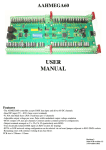
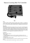
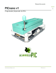
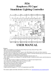
DMX36
USER MANUAL
Features
-The DMX36 controller accepts DMX data input and drives 36 DC channels.
-Quad DC input (5V, 7 - 35V) (large screw terminals)
-4x 30A mini blade fuses (30A overall max per 9 channels)
-36 DC outputs (5A max per channel). Common anode (common positive) configuration.
-Output terminals arranged as +, Ch, Ch, Ch (particularly suits RGB)
-True electrically isolated DMX input with ESTA pinout (2x RJ45 sockets for looping)
-Remaining zones will continue working if any fuse blows
PCB size is 165mm x 93mm
Revision 1
Suits PCB revision 1.1
23 June, 2014
Connections
Dmx Data
There are 2 RJ45 dmx sockets on the board. These are designed for loop in and loop out.
If the DMX36 is the last dmx device on the dmx cable then the signal should be terminated with the termination jumper.
Basically if only 1 cable is plugged in to the dmx sockets then the termination jumper should be installed. If both sockets
are used then the termination jumper should be left off.
The DMX36 uses the ESTA pinout. If connecting to a LOR device (dongle or controller) a crossover cable or adaptor
will need to be connected in between.
DC Power Input
The 4 large 2 way green connectors are the DC inputs from your power supply. Each of the 4 zones of 9channels can use
a separate power supply or you can feed them all from one common power supply. Separate wiring (back to the power
supply) for each of the zones is recommended to minimise voltage drop. The + terminals are positive and the - terminals
are negative. The board will control any DC voltage up to 35V. At least 1 zone will need to be 5V or above. If all 4 zones
are running off 5Vit is necessary to install the “5V only” jumper. Installing this jumper if more than 5.5V is applied to
any of the zones may damage the pcb. The negative (-V) terminals are commoned between the 4 zones so this must be
taken into account when wiring up to the power supply/supplies. Each of the 4 zones has a standard ATX (automotive)
fuse adjacent to the power terminals. The DMX36 comes supplied with 10A fuses fitted. Fuses up to 30A can be used.
It is recommended changing the fuse to the closest size for the total current that the zone will be supplying.
Dimmer Outputs
There are 36 channel outputs; 18 per side with each side divided into 2 zones. Each side can be run at the same, or a
different supply voltage. Any DC voltage in the range of up to 35V can be used for each of the banks.
The maximum load per channel is 5 Amps, but remember that the overall limit per bank/zone of 9 outputs is 30 Amps.
This means that you can't turn on all 9 outputs of a zone with the maximum load. In reality, this should not be a problem
as most loads will be less than 2 Amps.
There are 36 dimmer outputs which are in banks of 9 with each zone of 9 fused separately. Each group of 3 outputs is
grouped into 4 terminals. These are the 3 outputs and a common positive. RGB lights with a single common anode should
have the common wire connected to the terminal + (the 4 banks have common -ve terminals) and the red, green and blue
wires to channels 1,2,3 (or 4,5,6 etc). The order and specific channels is actually dependant on what is configured in your
sequencing software. For lights that have single colours (or single channels) per pair of wires then 1 wire gets connected
to the + and 1 gets connected to the channel output. For led lights which require the polarity to be around the right way
then the anode (positive) gets connected to + and the cathode (negative) goes to the channel. For lights that do not have
three channels commoned then 3 wires will be joined and fitted to the + for the 3 channels.
See the Connection Examples section for the various methods of connecting lights.
ICSP Connector
An ICSP (in circuit serial programming) header connector is provided for initial programming of the microprocessor and for
program (firmware) updates.
-2-
USING THE DMX36
Status Leds
There are 3 small LEDs near the centre of the PCB adjacent to the micro.
Red led-5V Power, Blue led-MODE, Green led-DATA
-Red led
5V power
-Blue MODE led flashing slowly.
Green DATA led off.
Test mode
Test mode takes precedence over normal running so errors/status message other than test mode won’t be displayed if in test mode.
-Blue MODE led on solid.
Green DATA led flashing 10 Hz. Normal run mode. Dmx packets being received
-Blue MODE led on solid.
Green DATA led off.
Normal run mode. No dmx data
-Blue MODE led flashing 10Hz.
Green DATA led off.
PGM/Address setting mode. No valid address yet
-Blue MODE led flashing 10Hz.
Green DATA led on.
PGM/Address setting mode. Valid address received
Start Channel
The start channel is set via the PGM switch and data being sent to the board. DMX addresses can be anywhere between 1 and 512.
The address of the DMX36 can be anywhere in the range of 1 to 476 (a start address of 476 uses the addresses from 476 to the
maximum 512). If the address is set outside of this range an error is indicated via the 2 status leds. See Status Leds. The start
channel can be changed at any time by turning on the PGM switch and sending the data. The start address is sent and stored as 2
8 bit numbers. For a start address of 1-255 the 2nd address/channel should be 0. For addresses over 255 (255-476) the 2nd start
address channel is set to 1 and the 1st address channel is set to the start address minus 256.
When you receive your DMX36 it will have a DMX start address of 1. That is, it will respond to channels 1 to 36. To change
the start address perform the following procedure:
•
•
•
•
•
•
•
Power up the DMX36.
Connect a DMX source of DMX data like a sequencer, test software or dedicated start channel programmer (like da_start)
etc that you can set at least channels 1 & 2 to a DMX address to the full 0-255 range (not a 0-100% setting)
Set DMX channel 1 to value 1..255 to the required setting for the new DMX start address
Set DMX channel 2 to a non-zero value if it’s required to add 256 to the new DMX start address
Turn on the PGM dipswitch. The MODE led will flash and the DATA led will be off.
After a valid start address in the range of 1-476 is received the DATA led will turn on. The new DMX start address is then
stored in the EEPROM
Turn off the PGM switch and the DMX36 is ready to use with the new start address.
Test Mode
There is a switch which places the control into a test mode. In this mode a test program runs and all 36 outputs are cycled
through. This mode allows for soak testing of lights without the need for a source of dmx data. The control will cycle through
12 modes of testing from 1 led on at a time, through all reds on, all greens etc.
Connection Examples
Typical connection arrangement
showing 3 leds and a 12V power
supply. The lights can be single
colour, multicolour, RGB or
whatever. For individual lights
with 2 wires the positive wires
would be joined and connected to
the +V terminal.
Connection example
showing channel 1
connected to a second
power supply. This
method is used where
lights other than the main
power supply voltage is
needed. This method can
be used for ACL strobes
or similar devices. The
primary power supply
powering the DMX36
needs to be in the range of
5V to 35V DC. The secondary power supply can be any
voltage up to a maximum of 60V DC. This method can also
be used if an output is used to control a relay at a voltage
other than the supply voltage.
As it possible to run the DMX36 off up to 4 different power
supplies a light on 1 zone can be powered by the supply on
another zone.
-3-
Firmware Updates
Firmware update can be loaded via the onboard USB socket or if necessary
through the ICSP header with a Pickit3 pic programmer. Pin 1 of the ICSP header is
marked on the pcb and is shown to the right. Ensure the pin 1 of the header is
aligned with pin 1 of the programmer.
If the firmware is being updated it is recommended to remove the fuses of any
channels that are dimmed down to less than 100% with the Zone Volts jumpers as
there is a possibility that during the firmware update process the leds may be turned
on with 100% voltage. Under normal circumstances all leds are turned off and
should remain off during the firmware update process.
Plug your PicKit 3 into a spare USB port, then start MPLAB. Once it has loaded, click
Configure > Select Device to bring up the device selection window. From the device
drop-down list, select PIC16F1823 and click OK.
A dialog saying "New firmware must be downloaded for PicKit 3 to work with the part selected." may pop up at this stage. If it
does, click OK and wait for MPLAB to download the programming firmware to the Pickit 3. You will see some activity in the
PicKit 3 tab of the output window for up to a minute or so. When MPLAB is ready you will see "PicKit 3 Connected" and possibly
an error stating "PK3Err0045: You must connect to a target device to use Pickit 3". This is not a problem and just a warning that
the PicKit 3 cannot "see" the chip yet.
Then, click File > Import and browse to the DMX 1.1 HEXFILE.hex file (latest version at time of writing) and click Open. The
last line of the build tab of the output window should read "Loaded C:\...DMX36****.HEX."
Now, connect the PicKit 3 the 6 pin ICSP header next to the micro. Make sure the arrows on the Pickit 3 and the 6 pin header are
aligned. Then power up the DMX36. The PicKit 3 tab of the output window should now read "Target Detected”.
Click Programmer > Program to initiate the ICSP operation. The PicKit 3 tab of the output window will show "Programming...",
then "Programming/Verify complete" once it is done. Disconnect the PicKit 3. The PicKit 3 tab of the output window will show
"Target Removed".
Faultfinding
Fault
Solution/solutions
Power Led (red led) not lit
-Fuse/s blown (note the control only needs power to 1 zone for power led to be on and for that
zone to work). Check fuses
-Power supply faulty or not turned on.
-Power supply section of pcb damaged. No user repairable parts. Return for repair
1 or more Zones not working
-Fuse for that zone is blown, power supply powering that Zone is faulty or there is a wiring fault
Channel failing to turn on
-Mosfet transistor has been damaged. Can be replaced but warranty may be voided. The mosfet
must be replaced with the exact same type to ensure correct operation
-PCB track has been burnt out. Should be evident if bottom of pcb is inspected
Channel turned on all the time
-Mosfet transistor has been damaged. Can be replaced but warranty may be voided. The mosfet
must be replaced with the exact same type to get correct operation
No DMX signal
-Termination jumper is installed when both DMX sockets are in use
-No data is being sent. Check software, dongle, cable etc
-DMX (RS485) receive IC is damaged. IC is socketed for easy replacement
-Insufficient channels being sent by sequencing software
Fuse blowing
-Fuse selection too low for lights that are connected
-1 or more lights connected have short circuited wires
-4-
Warranty
This dmx light controller is covered by a warranty for a period of 12 months from the time of purchase.
The warranty covers only faulty material and workmanship if properly setup and operated in accordance with the specifications
and setup sections of this document.
The repair and or replacement of this controller will only be at the workshop of Alan Hanson. The cost of freight to/from will be
borne by the user.
The warranty does not cover damage to the controller due to misuse i.e.. shorting of outputs, connecting AC supply, connecting
a supply higher than the rated voltage.
The controller is supplied as is. Alan Hanson and Hanson Electronics reserves the right to make changes to the firmware,
specifications and the design without notification.
Misuse, using this for other than its designed use, water damage, mechanical damage or attempting to modify or repair your
controller will void this warranty.
Alan Hanson and Hanson Electronics shall not be liable for any incidental damage, inconvenience, rental, loss of profits or any
other loss due to the unsuitability, failure or use of this controller.
If the user does not agree to these terms the cost of the product (minus freight) will be refunded on the return of the product. The
controller must be in unused condition and must be returned within 14 days.
Please return this controller with a copy of your invoice if it develops a fault. Any controller returned without a copy of the
invoice will be charged at a standard repair rate. The warranty does not cover freight.
Mounting standoff drilling pattern.
(Scaled. Not 1:1)
Enquiries/Repairs :Hanson Electronics
Alan Hanson
16 York St
Eaglehawk Victoria 3556
Mobile 0408 463295
email hanselec @ gmail.com
-5-