1
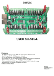
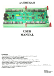
PI36
Raspberry PI Cape/
Standalone Lighting Controller
USER MANUAL
Features
-Mates with a Raspberry Pi running the Falcon Player (previously Falcon Pi Player, FPP)
-PI is powered by the onboard regulator.
-PI mounts above the board with "easy" access to the USB, Ethernet, SD, audio and video connectors.
-Mounts to suit the 2 standoff and 4 standoff varieties of the PI. Note these mounts may not suit some version
PI's as the footprint varied depending on manufacturer.
-36 DC channels rated at 30A per 18 channels. Individual channels rated at 3A.
-2801 output for carry over to 2801DC15 or 2801DC30 boards. Alternatively 2801 pixels could be hooked up
to this output.
-7-35V DC input. If only 5V outputs are used there is a 5V input for powering the board.
-Test switch with a matching LED to turn on or off a test mode.
-Power LEDs for the 2 DC inputs and the 5V power.
-Real time clock onboard for show scheduling.
-30A (max) ATO (automotive) blade fuse
-Common anode (positive) configuration.
-Output terminals arranged as V+, Ch, Ch, Ch (particularly suits RGB)
This manual, updates and further information on the PI36 are on .hansonelectronics.com.au/product/pi36/
Contents
............................................................................................................................................................................................................. 2
........................................................................................................................................................................................................... 2
Power Input ...................................................................................................................................................................................... 2
Power ................................................................................................................................................................................................ 2
Outputs ............................................................................................................................................................................................ 3
.............................................................................................................................................................................................................. 3
THE PI36 ............................................................................................................................................................................................. 3
it works............................................................................................................................................................................................. 3
.......................................................................................................................................................................................................... 3
.......................................................................................................................................................................................................... 3
Output configuration within Falcon Player (FPP) ............................................................................................................................ 3
configuration within Falcon Player (FPP) ....................................................................................................................................... 3
Mode ................................................................................................................................................................................................ 3
STUFF .................................................................................................................................................................................................. 4
THE PI ................................................................................................................................................................................................ 4
OTHER STUFF................................................................................................................................................................................... 4
............................................................................................................................................................................................................. 5
EXAMPLES ........................................................................................................................................................................................ 6
.............................................................................................................................................................................................................. 7
The PI36 is a 36 channel DC dimmer board that also functions as a dock for a Raspberry PI and has a real time
clock on it to allow shows to be scheduled with Player (Falcon Pi Player, FPP). The PI36 requires a Raspberry
PI plugged in with FPP installed to operate. In conjunction with Falcon Player the PI36 can operate as a
standalone 36 channel sequence playback device or as a 36 channel E1.31 DC dimmer. A USB dongle can be
connected to the PI and a DMX universe generated from it. A wifi dongle (WIPI or similar) can be connected to
the PI for wireless access. The Ethernet connection of the PI can stream out dozens of universes of E1.31 data. If
additional DC channels are required then a 2801DC15 or 2801DC30 board can be connected.
Connections
CN1
The connector CN1 on the PI36 connects to a Raspberry Pi via a 26 or 40 way ribbon cable depending on the PI model.
This is the only connection between the 2 boards and the correct cable type should be installed. If you have a later
model PI it will likely have the 40 way connector. On early PIs it was a 26 way connector. The ribbon cable should be
connected to the PI36, then the PI and then the PI attached to the 4 standoffs on the PI36. There are 6 possible mounting
points depending on the 2 common PI footprints.
DC Power Input
The 2 large 2 way green connector is the DC inputs from your power supply. The +V terminal is positive and the GND
terminal is negative or ground. Any DC voltage in the range of 5V to 35V can be used. There is a standard ATO
(automotive) fuse adjacent to the power terminals. The board comes supplied with 10A fuses fitted. Fuses up to 30A
can be used. It is recommended changing the fuse to the closest size for the total current that the board is controlling.
5V Power
If both DC dimmer banks are running off 5V then it is also necessary to connect the 5V to the CN2 5V terminal. This
will give the control circuitry the 5V it requires as the regulator is unable to supply 5V if the incoming supply is 5V to
the DC dimmer connectors. The 5V must be 5V +/- 0.1V. Too low and the circuitry on the PI may not work and too
high and damage may result to the PI36 and/or the PI. There is protection on the PI36 but it is limited in the abuse that it
will protect against. If the DC power inputs aren’t used then 5V power should be connected to CN2. It is also possible
to use CN2 as a low current source of 5V power. No more than 100mA should be sourced from this terminal if it is used
as an output.
2
Dimmer Outputs
There are 36 channel outputs. The maximum load per channel is 3 Amps, but the overall limit is 30 Amps per bank of
18. This means that you can't turn on all 18 outputs with the maximum load. In reality, this should not be a problem as
most loads will be less than 2 Amps.
Each group of 3 outputs is grouped into 4 terminals. These are the 3 outputs and a common positive. RGB lights with a
single common anode should have the common wire connected to the terminal +V and the red, green and blue wires to
channels 1,2,3 (or 4,5,6 etc). The order and specific channels is actually dependant on what is configured in your
sequencing software. For lights that have single colours (or single channels) per pair of wires then 1 wire gets connected
to the +V and 1 gets connected to the channel output. For led lights which require the polarity to be around the right
way then the anode (positive) gets connected to +V and the cathode (negative) goes to the channel. For lights that do
not have three channels commoned then 3 wires will be joined and fitted to the +V for the 3 channels.
LEDS
There are 4 LEDs on the PI36 as well as a number on the Raspberry PI. See the falconchristmas website for details on
the LEDs on the PI. The leds on the PI36 are 2 for the power for the 2 banks of DC dimmers. These are labelled PWR1
and PWR2. There is 1 to indicate that there is 5V on the board and there is 1 to indicate that test mode is running.
USING THE PI36
How it works
The smarts of the PI36 are actually within the Raspberry PI and the Falcon Player software. Sequences are created and
copied to the USB thumbdrive and the PI either runs by itself as a standalone playback device with the onboard
scheduler in the Falcon Player. Alternately it can be configured as an E1.31 device with the sequence playback
occurring on a computer or another Raspberry Pi, BeagleBoneBlack or similar. This is in bridge mode within the Falcon
Player.
The official home of the Falcon Player software is . . Information on configuring the Falcon Player, downloads etc are
hosted there.
Data
The pcb has a terminal blocks for getting the data out of the pcb to expansion DC boards. It is a removable screw
terminal and the wire that goes into each position is marked on the pcb. The data into the pcb goes out to other boards or
pixels.
Power
The pcb can be powered by any DC voltage in the range of 5V or 7V to 35V. If all the LEDs on the DC dimmer outputs
are 5V then the user must connect 5V to the 5V terminals on CN2. The 5V must be 5V +/- 0.1V. Too low and the
circuitry on the PI may not work and too high and damage may result to the PI36 and/or the PI. There is protection on
the PI36 but it is limited in the abuse that it will protect against. The PI is powered via the PI36 board via the expansion
GPIO header of the
PI and it doesn’t need 5V connected via the traditional micro usb connector.
DC Output configuration within Falcon Player (FPP)
The 36 outputs of the PI36 are connected to the XXXX connection of the Raspberry Pi. Within the FPP you need to go to the
XXXX tab, go down to XXXX and select XXXX. To enable more than the 36 channels on the PI36 if a 2801DC15, 2801DC30,
2801 pixels or a combination of the previous then the required number of channels should be selected.
Clock configuration within Falcon Player (FPP)
The PI36 has a battery backed real time clock on it. The CR2032 battery used is specified to give about 12 years of battery backup.
If the battery isn’t installed or if the battery is flat/failed the time in the PI will be lost and schedules will not run on time.
Test Mode
The PI36 has an inbuilt test mode and an LED to indicate that it is currently running in test mode. Pushing the test mode
pushbutton on the pcb will enable the test mode, the LED will turn on and something will happen. Pressing it again will
turn off test mode and the LED.
3
PI STUFF
The Raspberry PI is powered via the GPIO expansion header of the PI and doesn’t need the power to be applied via
micro USB connector.
The following details are how the PI36 interconnects with a Raspberry PI. This information is required for configuring
Falcon Player.
The test switch is connected to pin 12 of the expansion header (GPIO18). The switch switches to ground.
The test mode LED is connected to pin 11 of the expansion header (GPIO17). The –ve of the LED is connected to
ground and the +ve is connected to GPIO17.
The 36 DC dimmer channels are connected as 2801 pixel channels with the clock being on pin 23 (GPIO11). Data is
on pin 19 (GPIO10). If there are further DC channels connected via a 2801DC15 or 2801DC30 or 2801 pixels
connected then they are configured within the Falcon Player.
MOUNTING THE PI
The PI mounts to the PI36 via either 2 or 4 M2.5 standoffs (depending on the PI model) and via an IDC ribbon cable.
Depending on which model of Raspberry PI you have, connect either the 26 to 26 way IDC cable or 26 to 40 way IDC
ribbon cable between the PI36 and the PI. The standoffs will either be M2.5 x 25 nylon spacers or alternately M2.5 x 8
spacers screwed together to make a M2.5 x 24 spacer. The spacer mounts with the M2.5 x 6 thread through the PI36
with the nuts under the PI36. Match up the mounting holes that suit your PI (some have 2 and some have 4). After the
standoffs are screwed to the PI36 then screw the PI to the standoffs with the M2.5 screws.
Because of the low clearances between components and the mounting points on the Raspberry PI only nylon screws
and standoffs shows be used.
CONNECTING OTHER STUFF
The PI36 can be connected to 2801DC15 and 2801DC30 boards to add additional DC channels. The PI can have a USB
Open DMX compatible dongle added to give a universe of DMX channels, it can have a wifi dongle like the WIPI for
remotely accessing the PI and the Ethernet connection of the PI can stream dozens of universes of E1.31 data. The PI
also has audio and video outputs that can be used.
4
FAULTFINDING
Fault
Magic smoke is released
Solution/solutions
-Go to jail. Do not pass go. Do not collect $200
-Apply for magic smoke restocking. Fee will be charged
5V LED is not lit
-Both fuses are blown
-Power is not connected in the right polarity
-A short is on the 5V terminal
-A short is on the 2801 pixel output or too great a load is connected
Dimmer bank LED is not lit
-Fuse is blown
-Power to the connector is less than approximately 2.7V
-Power is connected in the wrong polarity
Raspberry PI Leds not lit
installed
-Cable between PI GPIO header and PI36 CN1 misaligned or not
No output lights working
-Fuse/s is blown
-Data is not being sent out by computer or Falcon Player. Try test mode.
-The schedule within the Falcon Player isn’t active
Channel failing to turn on
-Mosfet transistor has been damaged. The mosfet must be replaced with
the exact same type to ensure correct operation
-PCB track has been fused. Should be evident if bottom of the pcb is
inspected
Channel turned on all the time
-Mosfet transistor has been damaged. The mosfet must be replaced with
the exact same type to get correct operation
Fuse blowing
-Fuse selection too low for lights that are connected
-1 or more lights connected have short circuited wires
5
CONNECTION EXAMPLES
Figure 1 shows the typical
power supply connections. 1 of
the power supplies needs to be
in the 7-36V range. If the power
supply has sufficient power
available then it can be used to
power both output banks. If 1
power supply is in the 7-36V
range then the other power
supply can be any voltage in the
0 to 36V range.
Figure 1- Typical power connection
Figure 2 shows
how the power is
connected if only
5V lights are
used. In this case
the 5V power
connector must
be connected to.
If only the PI and
the board (but no
DC ouputs) are
to be powered
then a 5V power
supply connected
to
the
5V
connector is all
that is required.
Figure 2 - Connection when only 5V is used
Figure 3 shows the 3 common method of connecting lights
to output channels. Channels 1 to 3 show a RGB 3 channel
set of leds connected with the common positive connected
to the +V terminal. Channels 4 to 6 show 3 single channel
lights connected with the 3 positives connected to the 1
+V terminal. Channels 6 to 12 show 3 pairs of 2 channel
lights connected.
Figure 3 - 3 channel, 1 channel and 2 channel
6
Figure 4 shows how to connect between a PI36 and a 2801DC15 to add
additional DC channels. Further 2801DC15 or 2801DC30 boards can
be added or alternatively 2801 pixels can be connected. If 2801 pixels
are added then the GND connection for the pixels should be connected
to both the pixels and also the PI36 GND connection. The +5 should
not be connected to either the pixels or the pixel power supply.
Figure 4 – PI36 to 2801 DC output
Figure 5 shows the Raspberry PI
mounted in its position on top of the
PI36. The PI is connected via the
supplied IDC cable and connects to
the GPIO header of the PI and CN1
on the PI36. See the Raspberry PI
documentation or see
falconchristmas.com for info on the
location of the SD or micro SD
connector, video output, audio output
etc.
Figure 5 - PI36 with Raspberry PI mounted
7
WARRANTY
This light controller is covered by a warranty for a period of 12 months from the time of purchase.
The warranty covers only the PI36 controller and not any connected lights, power supplies or Raspberry Pi.
The warranty covers only faulty material and workmanship if properly setup and operated in accordance with the
specifications and setup sections of this document.
The repair and or replacement of this controller will only be at the workshop of Alan Hanson. The cost of freight
to/from will be borne by the user.
The warranty does not cover damage to the controller due to misuse i.e.. shorting of outputs, connecting an AC supply,
connecting a supply higher than the rated voltage etc
The controller is supplied as is. Alan Hanson and Hanson Electronics reserves the right to make changes to the
specifications and the design without notification.
Misuse, using this for other than its designed use, water damage, mechanical damage or attempting to modify or repair
your controller will void this warranty.
Alan Hanson and Hanson Electronics shall not be liable for any incidental damage, inconvenience, rental, loss of
profits or any other loss due to the unsuitability, failure or use of this controller.
If the user does not agree to these terms the cost of the product (minus freight) will be refunded on the return of the
product. The controller must be in unused condition and must be returned within 14 days.
Please return this controller with a copy of your invoice if it develops a fault. Any controller returned without a copy
of the invoice will be charged at a standard repair rate. The warranty does not cover freight.
Mounting standoff drilling patterns . (Scaled. Not 1:1)
Enquiries/Repairs/Contact Details :Hanson Electronics
Alan Hanson
16 York St
Eaglehawk Victoria Australia 3556
Mobile 0408 463295
email hanselec @ gmail.com web. .hansonelectronics.com.
U
U
31TwwwU
auU31T
8