1
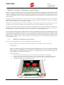
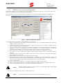
SINUS PENTA BACnet PROGRAMMING INSTRUCTIONS 1. BAC NET F IELDBUS C OMMUNICATIONS B OARD BACnet is a data communication protocol specifically designed for building automation and control systems. Building automation systems (or building management systems) using BACnet incorporate a wide variety of applications and components into the one system. The applications cover heating, ventilation and air conditioning (HVAC), power monitoring, lighting control, access control and fire alarms for the entire building. Developed under the guidance of the American Society of Heating, Refrigerating and Air-Conditioning Engineers (ASHRAE), BACnet is an American national standard, a European standard, a national standard in more than 30 countries and an ISO global standard. The BACnet communications board allows interfacing a Sinus PENTA inverter with an external control unit through a communications interface using a BACnet protocol of either BACnet IP or BACnet MSTP. The user configuration software allows the setting of global Node ID and Network Number in addition to configuration of IP address and Subnet mask to suit BACnet IP using the Ethernet protocol and System Node, Baud rate, party, data bits and stop bits for BACnet MSTP using the RS485 protocol. For the purposes of this manual, A BACnet device can be considered to be a piece of hardware such as a Sinus Penta drive. Each BACnet device will have a number of associated BACnet Objects, corresponding to parameters, measurements, and the like. In this application, the Sinus Penta Drive has a minimum of 13 objects of the ‘Analogue Value’ type for communicating various parameters between the drive and the BACnet network. This minimum number of objects can be increased to include additional measurements as required by the user. 1.1. BAC N E T C OMMU N I C A TI ON C A RD S Two PCB’s are provided as part of the Sinus PENTA BACnet fieldbus option: 1. ES919 interface board – plugs into Slot B of the ES821 control card inside the Sinus Penta. <PIC OF ES919> Once board ES919 is fitted, connector DB9 port/RS-485 installed on the inverter will automatically disable. To use the DB9/RS485 port temporarily to program the drive (e.g using Remote Drive) simply toggle the DIP switches SW1 on the ES919 to enable/disable. The RJ45 keypad/modbus port is unaffected by the addition of the ES919. To install the ES919: Turn off the inverter and wait 5 minutes for the DC bus capacitors to discharge Remove the front cover allowing access to the expansion ports on the ES821 control card Fit ES919 ensuring that all contacts enter the relevant housing in the signal connector Configure DIP switches as described above Figure 1 - Location of the mounting position of ES919 Page 2 of 9