Download ERM-MUX/Plus Operation Manual

Transcript
USER MANUAL
ERM-MUX-plus
E1 Multiplexer
Rack Type, 4U
CTC Union Technologies Co., Ltd.
The information in this publication has been carefully checked and is believed to be entirely accurate at the time of
publication. CTC Union Technologies assumes no responsibility, however, for possible errors or omissions, or for any
consequences resulting from the use of the information contained herein. CTC Union Technologies reserves the right to
make changes in its products or product specifications with the intent to improve function or design at any time and
without notice and is not required to update this documentation to reflect such changes.
CTC Union Technologies makes no warranty, representation, or guarantee regarding the suitability of its products for
any particular purpose, nor does CTC Union assume any liability arising out of the application or use of any product
and specifically disclaims any and all liability, including without limitation any consequential or incidental damages.
CTC Union products are not designed, intended, or authorized for use in systems or applications intended to support or
sustain life, or for any other application in which the failure of the product could create a situation where personal injury
or death may occur. Should the Buyer purchase or use a CTC Union product for any such unintended or unauthorized
application, the Buyer shall indemnify and hold CTC Union Technologies and its officers, employees, subsidiaries,
affiliates, and distributors harmless against all claims, costs, damages, expenses, and reasonable attorney fees arising
out of, either directly or indirectly, any claim of personal injury or death that may be associated with such unintended or
unauthorized use, even if such claim alleges that CTC Union Technologies was negligent regarding the design or
manufacture of said product.
TRADEMARKS
Microsoft is a registered trademark of Microsoft Corp.
HyperTerminal™ is a registered trademark of Hilgraeve Inc.
WARNING:
This equipment has been tested and found to comply with the limits for a Class A digital device, pursuant to Part 15 of
the FCC Rules. These limits are designed to provide reasonable protection against harmful interference when the
equipment is operated in a commercial environment. This equipment generates, uses, and can radiate radio frequency
energy and if not installed and used in accordance with the instruction manual may cause harmful interference in which
case the user will be required to correct the interference at his own expense. NOTICE: (1) The changes or modifications
not expressively approved by the party responsible for compliance could void the user's authority to operate the
equipment. (2) Shielded interface cables and AC power cord, if any, must be used in order to comply with the emission
limits.
CISPR PUB.22 Class A COMPLIANCE:
This device complies with EMC directive of the European Community and meets or exceeds the following technical
standard. EN 55022 - Limits and Methods of Measurement of Radio Interference Characteristics of Information
Technology Equipment. This device complies with CISPR Class A.
WARNING:
This is a Class A product. In a domestic environment this product may cause radio interference in which case the user
may be required to take adequate measures.
CE NOTICE
Marking by the symbol CE indicates compliance of this equipment to the EMC directive of the European Community.
Such marking is indicative that this equipment meets or exceeds the following technical standards: EN
55022:1994/A1:1995/A2:1997 Class A and EN61000-3-2:1995, EN61000-3-3:1995 and EN50082-1:1997
CTC Union Technologies Co., Ltd.
Far Eastern Vienna Technology Center (NeiHu Technology Park)
8F, No. 60, ZhouZi St.
NeiHu, Taipei, 114
Taiwan
Phone: +886-2-2659-1021
FAX: +886-2-2799-1355
ERM-MUX/Plus Installation and Operation Manual
E1 Multiplexer, Rack Mount
This manual supports the following models:
ERM-MUX/Plus
Version 3.0 January 2006
This document is the draft of the to be released manual. Please check CTC Union's website for any updated manual or
contact us by E-mail at [email protected]. Please address any comments for improving this manual or to point out
omissions or errors to [email protected]. Thank you.
Table of Contents
CHAPTER 1 INTRODUCTION ...............................................................................................................................9
1.1 GENERAL FEATURES ......................................................................................................................................... 10
1.1.1 Power Supply Modules............................................................................................................................... 11
1.1.2 CPU Control Card..................................................................................................................................... 11
1.1.3 E1 Line Card............................................................................................................................................. 11
1.1.4. N64K/V35 Line Card ................................................................................................................................ 12
1.1.5 A/SYNC-128K Line Card ........................................................................................................................... 12
1.1.6 G703-64K Line Card ................................................................................................................................. 12
1.1.7 FXS Line Card........................................................................................................................................... 12
1.1.8 FXO Line Card.......................................................................................................................................... 13
1.1.9 E&M Line Card......................................................................................................................................... 13
1.1.10 MAGNETO Line Card ............................................................................................................................. 13
1.1.11 X.50 Line Card ........................................................................................................................................ 13
1.1.12 SUB-E1 Line Card................................................................................................................................... 13
1.1.13 Additional Features ................................................................................................................................. 13
1.2 TECHNICAL SPECIFICATIONS.............................................................................................................................. 14
1.2.1 E1 Line Line Card ..................................................................................................................................... 14
1.2.2 N64/V35 Line Card.................................................................................................................................... 14
1.2.3 A/SYNC-128K Line Card ........................................................................................................................... 14
1.2.4 G703-64K Line Card ................................................................................................................................. 14
1.2.5 E&M Line Card......................................................................................................................................... 16
1.2.6 FXO Line Card.......................................................................................................................................... 16
1.2.7 FXS Line Card........................................................................................................................................... 16
1.2.8 MAGNETO Line Card ............................................................................................................................... 16
1.2.9 X.50 Module Line Card.............................................................................................................................. 16
1.2.10 SUB-E1 Line Card................................................................................................................................... 17
1.2.11 Power Modules........................................................................................................................................ 17
1.2.12 Physical Specifications............................................................................................................................. 17
CHAPTER 2 INSTALLATION .............................................................................................................................. 18
2.1 INSTALLING BRACKETS ON CHASSIS .................................................................................................................. 18
2.2 POWER MODULES AND LINE CARD INSTALLATION ............................................................................................. 19
2.3 AUXILIARY CONNECTIONS ON REAR OF CHASSIS................................................................................................ 19
2.4 CONNECTING SNMP NETWORK MANAGEMENT ACCESS ..................................................................................... 20
2.5 CONNECTING NMP NETWORK MANAGEMENT ACCESS ....................................................................................... 20
2.6 CONNECTING MONITOR/CONTROL TERMINAL .................................................................................................... 21
2.7 CONNECTING G.703 EXTERNAL CLOCK ............................................................................................................. 21
2.8 CONNECTING E1 CIRCUITS ................................................................................................................................ 21
2.9 CONNECTING I/O CARDS ................................................................................................................................... 21
2.10 CONNECTING SYNC TAIL CIRCUITS .................................................................................................................. 21
CHAPTER 3 LED INDICATORS AND CABLE PIN DEFINITIONS.................................................................. 23
3.1 FRONT PANEL LED INDICATORS ........................................................................................................................ 23
3.2 INTERFACE CONNECTOR PINS AND DEFINITIONS ................................................................................................ 25
3.2.1 N64K/V.35 Card........................................................................................................................................ 25
3.2.2 A/SYNC-128K Card................................................................................................................................... 27
3.2.3 G703-64K Card........................................................................................................................................ 27
3.2.4 E&M Card................................................................................................................................................ 27
3.2.5 FXS Card ................................................................................................................................................. 27
3.2.6 FXO Card................................................................................................................................................. 27
3.2.7 MAGNETO Card ...................................................................................................................................... 28
3.2.8 X50 Card.................................................................................................................................................. 28
3.2.9 SUB-E1 ..................................................................................................................................................... 28
Table of Contents
CHAPTER 4 HARDWARE SETTINGS ................................................................................................................ 29
4.1 E1 CARD .......................................................................................................................................................... 29
4.2 N64K/V35 CARD.............................................................................................................................................. 29
4.3 E&M CARD ...................................................................................................................................................... 30
4.3.1 Signaling Type Setting ............................................................................................................................... 30
4.3.2 2/4Wire Mode Setting Selection ............................................................................................................... 30
4.3.3 Audio Attenuator Settings .......................................................................................................................... 31
4.4 SUB-E1 CARD .................................................................................................................................................. 32
CHAPTER 5 CONSOLE OPERATION................................................................................................................. 33
5.1 INITIAL SETUP .................................................................................................................................................. 33
5.1.1 Boot .......................................................................................................................................................... 33
5.1.2 INPUT PASSWORD .......................................................................................................................................... 33
5.1.3 MAIN MENU .................................................................................................................................................. 34
5.2 SET E1 CARD .................................................................................................................................................... 34
5.2.1 Set Frame Mode ........................................................................................................................................ 35
5.2.2 Set CRC Mode........................................................................................................................................... 35
5.2.3 Set Loop Back............................................................................................................................................ 35
5.2.4 Set Impedance ........................................................................................................................................... 35
5.2.5 Set Line Code ............................................................................................................................................ 36
5.2.6 Set Timeslot Cross Connect ....................................................................................................................... 36
5.3 SET I/O CARD ................................................................................................................................................... 37
5.3.1 N64K/V35 card configuration.................................................................................................................... 37
5.3.2 Set G703-64K Card ................................................................................................................................... 39
5.3.3 Set A/SYNC-128K Card ............................................................................................................................. 39
5.3.4 Set FXS card ............................................................................................................................................ 40
5.3.5 Set FXO Card............................................................................................................................................ 41
5.3.6 Set E&M Card........................................................................................................................................... 41
5.3.7 Set Magneto Card...................................................................................................................................... 41
5.3.8 Set X.50 Card............................................................................................................................................ 41
5.3.9 Setup SUB-E1 Card................................................................................................................................... 43
5.4 DISPLAY DEVICES CONFIGURATION ....................................................................................................... 44
5.5 SAVE CONFIGURATION ...................................................................................................................................... 45
5.6 RESET DEVICE CONFIGURATION TO DEFAULT .................................................................................................... 46
5.7 BROWSE/MODIFY SYSTEM PARAMETERS ........................................................................................................... 46
5.7.1 Display system version .............................................................................................................................. 46
5.7.2 Modify System Clock ................................................................................................................................. 46
5.7.3 Modify NMP/SNMP Parameter.................................................................................................................. 47
5.7.4 Modify E1 Backup Mode............................................................................................................................ 49
5.7.5 Password modification .............................................................................................................................. 49
5.7.6 System time modification ........................................................................................................................... 49
5.8 EXIT AND ENTER TO MONITORING STATE .......................................................................................................... 50
5.9 CATEGORY OF EVENTS AND ALARMS ................................................................................................................ 50
CHAPTER 6 TEST AND DIAGNOSIS .................................................................................................................. 51
6.1 E1 LOCAL LOOP ............................................................................................................................................... 51
6.2 E1 TO REMOTE LOOP ........................................................................................................................................ 51
6.3 E1 END-TO-END BI-DIRECTIONAL TEST ............................................................................................................. 51
6.4 LOOPBACK TEST FOR N64K/V35, A/SYNC-128K CARD ..................................................................................... 52
6.5 LOOP TEST FOR G703-64K CARD ...................................................................................................................... 52
6.6 X.50 MODULE LOOP TEST................................................................................................................................. 52
Table of Contents
CHAPTER 7 CLOCK AND SYNCHRONIZATION ............................................................................................. 53
7.1 SETTING CLOCK FOR WHOLE MACHINE ............................................................................................................... 53
7.1.1 E1A1's Recover clock................................................................................................................................. 53
7.1.2 E1A2's Recover clock................................................................................................................................. 53
7.1.3 Internal clock............................................................................................................................................. 53
7.1.4 I/O card clock............................................................................................................................................ 53
7.1.5 G703 external clock................................................................................................................................... 53
7.2 CONNECTION BETWEEN MULTIPLEXER AND SYNCHRONOUS TERMINAL DEVICE .................................................... 53
7.3 MUX WITH SYNCHRONIZATION TAIL CIRCUIT ..................................................................................................... 54
CHAPTER 8 APPLICATION OF MULTIPLE E1 PORTS................................................................................... 55
8.1 CONNECTION BETWEEN MUX AND DEVICE OF PUBLIC NETWORK ........................................................................ 55
8.2 CONNECTION WITH PROGRAM CONTROLLED EXCHANGER ................................................................................... 55
8.3 DATA CONNECTION AMONG MULTIPLE POINTS .................................................................................................... 55
8.4 THE EXTENSION AND EXPANSION OF DDN (DATA DISTRIBUTION NETWORK) ...................................................... 56
8.5 IMPLEMENTATION OF MULTIPLEXING CONNECTION FOR VOICE/SIGNALING .......................................................... 56
8.6 TYPICAL APPLICATION OF G703-64K CARD ........................................................................................................ 56
CHAPTER 9 SNMP OPERATION........................................................................................................................ 57
9.1 SNMP OVERVIEW ............................................................................................................................................. 57
9.1.1 Introduction............................................................................................................................................... 57
9.1.2 SNMP Operations...................................................................................................................................... 57
9.1.3 The Management Information Base............................................................................................................ 57
9.1.4 MIB Structure............................................................................................................................................ 58
9.1.5 SNMP Communities................................................................................................................................... 58
9.2 INSTALLATION INTRODUCTION .......................................................................................................................... 59
9.2.1 REQUIRED TOOLS AND SUPPLIES...................................................................................................................... 59
9.2.2 Procedure (Please refer to the attached drawing)...................................................................................... 59
9.2.3 Configuration General............................................................................................................................... 62
9.2.4 Terminal Connection ................................................................................................................................. 62
9.2.5 SNMP Configuration (terminal) ................................................................................................................. 63
9.3 WEB BASED MANAGEMENT SYSTEM ................................................................................................................. 67
Appendix A Specifications of ET100 card.......................................................................................................... 114
Appendix B Specifications of Expansion Chassis............................................................................................... 119
Appendix C Specifications of NMP ................................................................................................................... 122
Appendix D Basic Configuration ...................................................................................................................... 125
Appendix E Firmware upgrade......................................................................................................................... 126
Appendix F Version II NMP/SNMP functions.................................................................................................... 127
Appendix G New released functions for E1 module ........................................................................................... 131
Chapter 1 Introduction
The ERM-MUX/PLUS Time Division-Multiplexer supports four E1 channels that provide the functions of multiplexing
and cross-connecting of data/voice/CAS-signaling. The MUX is designed for multiplexing Nx64Kbps, 64K/128Kbps,
9.6Kbps synchronous data, asynchronous data below 38.4Kbps and voice signals into 2.048Mbps ITU-T G.703 E1
frames. The cross-connecting function include the intercrossing of CAS-signaling.
The types and quantity of subscriber's data and voice interface modules can be flexibly selected according to needs. The
modules can be plugged into any interface slots according to specific maintenance and application methods. All time
slots may be user defined. If more ports are required than are allotted by the main chassis, an extension chassis may be
connected later as required.
The ERM-MUX/PLUS supports SNMP and/or NMP GUI network management with local PC or via a dedicated
timeslot from the E1 line. The NMP GUI can manage more ERM-MUX/PLUS equipment via the E1 network in-line or
in nested structures. A console terminal mode is supported as well. When SNMP management mode is available and
selected, remote Telnet and HTTP embedded web server are alsp available for management.
The ERM-MUX/PLUS supports complete redundant functions for the electrical input service, the power module cards,
CPU card and E1 card. The E1 backup provides 1+1, 2+2, 1+3 modes. All of these cards are capable of automatic
switchover in case of failure. The system has complete warning and diagnostic functions for stable and reliable
operation.
Power supply options for 110V AC, 220V AC or -48V DC, ensure maximum flexibility for central office installations.
This equipment complies fully with all ITU-T standards for E1 transmissions..
9
Chapter 1 Introduction
1.1 General Features
Structure
19 or 23 inch rack mountable, 4U standard 18-slot chassis, from left to right:
The 1st and 2nd: POWERA slots.
The 3rd and 4th: POWERB slots.
The 5th :CPUA slot.
The 6th :CPUB slot.
The 7th :E1A slot.
The 8th :E1B slot.
Notice: Each slot has a mark in the front top of the case.
The 9th to 18th slots, defined as I/Oslot 01 ~ I/Oslot 10, may be used for plugging in any of the following user data
interface modules. The position, type, and number may be selected as required. Any channel of each module can be
multiplexed into any one of the four E1 interfaces, with timeslots configured at user discretion (either in sequence or
non-consecutively).
Cable connectors
Front panel
The I/O of each card is accessed from the front panel connectors.
Backplane
Provided with alarm terminals, connects to rack alarm circuits and under failure conditions, alarm signals are sent to
shelves/racks.
SNMP Gateway interface provides 100Base-TX unshielded twisted pair interface.
G.703 external clock interface provides two types of interfaces, balanced (RJ-45) and unbalanced (BNC) connectors.
RS-485 interface for cascading multiple racks, provided by RJ-45 x 2 connectors.
DB62 connector for connecting expansion rack.
Figure 1.1 ERM-MUX/Plus front panel
10
Chapter 1 Introduction
1.1.1 Power Supply Modules
POWERA/POWERB slots are used for the power modules. The modules are hot-swappable, capable of automatic
switch over in case of module failure, stable, and reliable, with 110VAC, 220VAC or -48VDC options.
1.1.2 CPU Control Card
CPUA/CPUB slots. can insert two CPU modules that automatically work in redundant operation mode. CPU modules
are responsible for all parameter setup from local PC or from the selected in-band E1line. The setup of the ERMMUX/Plus may be accomplished by:
Local PC connected by Ethernet to SNMP (can be extend to multiple cases with RS485 twisted-pair ).
Local PC connected by serial NMP port to NMP GUI.
E1 network connected to SNMP/NMP GUI.
Local terminal console mode.
1.1.3 E1 Line Card
E1A/E1B slots. can insert two E1 line modules that automatically work in redundant operation or separately. Each slot
can be selected as single E1 module (1xE1) /double E1 module (2xE1). When all E1's are selected as single (1xE1), the
4 E1 channels all support data/voice/CAS signaling cross connection and multiplexing.
Notice : two E1 modules must be configured to single or double E1 mode simultaneously.
1) Combinations:
single module single E1 mode (defined E1A slot)
single module double E1 mode (defined E1A slot)
single module single E1+single module single E1
single module double E1+single module double E1(2+2 redundant or 4xE1 channels)
2) working frame mode
CAS(PCM30) or CCS(PCM31)
3) Backup mode between E1 modules:
The E1 modules may operate in "working" or "backup" mode and are capable of automatic switchover in case of failure
(between E1A and the E1B).
Notice: when configured in "backup" mode, the E1 cables can be randomly connected to the E1A or E1B modules on
the front panel.
4) Backup modes between E1 lines:
1+1 Backup mode:
E1A1+E1A2
E1B1+E1B2
E1A1+E1B1
E1A2+E1B2
2+2 Backup mode:
E1A1+E1A2 and E1B1+E1B2
1+1/2+2 Line Backup Mode Rules:
a) If the line x breaks down for more than 1 second and the backup line is synchronized, then line x will switch to the
backup line. Line x then becomes the backup line and will send UNFRAME ALL ONE's for 10 seconds to force the
remote side to switch to the identical mode.
b) After 10 seconds, the backup line will stop sending UNFRAME ALL ONE's.
1+3 Line Backup Mode Rules:
(Both the local and remote sides have selected E1B1 as the backup line.)
a) When one of lines(X) looses synchronization for over 1 second and the E1B1 is already synchronized, the backup for
X will switch to E1B1. Line X will then become the backup line and send UNFRAME ALL ONE 10 seconds to force
the remote side to switch to the identical mode.
b) When line X recovers, it will switch back to E1A1, E1B1 will become the backup line and send UNFRAME ALL
ONE's for 10 seconds to force the remote side to switch to the identical mode.
11
Chapter 1 Introduction
5) System Clock Mode:
a) E1A1's recovered clock: picked up from the E1A1 receive signal.
b) E1A2's recovered clock: picked up from E1A2 receive signal (E1 module is a double E1).
c) Internal crystal clock.
4) G.703 Ext. clock (when this clock is enabled the internal crystal clock will be used for backup).
e) I/O clock: The timing is locked to the appointed IO Card's CH1 ETXCLOCK. The I/O modules that support this
function are: N64K/V35 module, G703-64K module, A/SYNC-128K module, and Sub-E1 module.
6) Time slot 0 pass through function (Sa bit 0-4):
7) E1 circuit diagnostic loop back:
a) Local Loop
b) To Remote Loop
c) Performance and BERT test
When the system CPU firmware upgraded to F/W V3.0 or higher, E1-V2.1 supports the E1 BERT test
functions
• System supports performance monitoring and BERT test through SNMP, NMP or Terminal console
according RFC 1406 recommendation,
• System supports CRC-4 and BPV monitoring: CURR ES / UAS , LONG ES / UAS
• System supports Loopback test and BERT test: display Rx error amounts, Error counts and Bit-error-rate
• System provides test patterns: 2E9-1, 2E11-1, 2E15-1, QRSS, ALL 0, ALL 1, ALT, 3 IN 24, 1 IN 16, 1
IN 8, 1 IN 4
• System provides Error Insertions: NONE, SINGLE, 10E-1, 10E-2, 10E-3, 10E-4, 10E-5, 10E-6, 10E-7.
1.1.4. N64K/V35 Line Card
Each card contains four Nx64K high-speed data interfaces. N=1 ~ 31 to data rate 64K to 1984Kbps for DCE mode.
1.1.5 A/SYNC-128K Line Card
Each card contains six up to 38.4K data rate for Asynchronous data interfaces, or six 64K/128K sync data interfaces.
1.1.6 G703-64K Line Card
Each card contains four G703-64K co-directional data interfaces.
1.1.7 FXS Line Card
Each card has 6 FXS ports, for connecting directly to phone. And also to establish the connection between phone and
FXO card for regular phone or hot-line application.
When system CPU firmware had been upgraded to F/W V3.0 or higher, the FXS-V2.0 or FXO-V2.0 card will provide
the E1 link status detection functions and phone line backup functions. It’s unnecessary to work with maintainer in the
field. The operator can monitor the status of FXS / FXO card and out line status through SNMP management in LEDs
status and backup functions. The backup function is set by jumpers inside the FXS / FXO card.
Two modes are provided:
Normal mode: Supports End-to-End of E1 link status monitoring
Backup mode: see Appendix H for further information
12
Chapter 1 Introduction
1.1.8 FXO Line Card
Each card has 6 FXO ports, for connecting to PBX switchboard. The system manager can create a connection between
FXO and FXS card.
When system CPU firmware had been upgraded to F/W V3.0 or higher, the FXS-V2.0 or FXO-V2.0 card will provide
the E1 link status detection functions and phone line backup functions. It is unnecessary to work with maintainer in the
field. The operator can monitor the status of FXS / FXO card and out line status through SNMP management in LEDs
status and backup functions. The backup function is set by jumpers inside the FXS / FXO card
Normal mode: Supports End-to-End of E1 link status monitoring
Backup mode: see Appendix H for further information
1.1.9 E&M Line Card
Each card includes 6 E&M ports (Ear and Mouth), offering either 2-wire or 4-wire voice transmission and E&M
signaling with TYPE1-TYPE5.
1.1.10 MAGNETO Line Card
Each card includes 6 magneto phone ports. Each can be connected with another magneto phone set at the remote E1
side.
1.1.11 X.50 Line Card
Each card contains five low-speed Asynchronous/synchronous data interfaces, Data rates:
19.2kBPS,9.6kBPS,4.8BkBPS,2.4kBPS . Standard compliance: RS232/V.24
1.1.12 SUB-E1 Line Card
Each card contains two G.703 E1 interfaces. Each SUB E1 may be multiplexed into any of the E1A1, E1A2, E1B1, or
E1B2 interfaces. For special applications requiring the need for Timeslot #0 to be able to transmit the data of CAS
signaling, the SUBE1 supports the function of Timeslot #0 By-Pass.
1.1.13 Additional Features
Optional expansion chassis for dense data ports application.
All modules are hot-swappable.
Note: The 9th ~ 18th slots are defined as I/O slots, and described logically as slot 01 ~ slot 10. The upper & back panel
of I/O slots have been clearly marked on the rack. Any of the logical slots 1 ~ 10 can random insert
N64K/V35,A/SYNC-128K, G703-64K, E&M, FXS, FXO, MAGNETO, Sub E1 or Ethernet Bridge I/O line cards.
13
Chapter 1 Introduction
1.2 Technical Specifications
1.2.1 E1 Line Line Card
E1 signal structure
٠ Frame format: CAS(PCM30)/CCS(PCM31), CRC ON/OFF
٠ Bit rate:
2.048Mbps
٠ Line codes:
HDB3/AMI
٠ Rx sensitivity: 0 ~ -43dB
٠ Transmitter driver capability:
1.5km over 0.5mm E1 cable
٠ Line impedance:
75 ohms (unbalanced) / 120ohms (balanced)
٠ Pulse amplitude:
nominal 2.37V (75ohm) / nominal 3.00V (120ohm)
٠ Pulse shape: ITU-T G.703 (see figure 1.2)
٠ Jitter tolerance: ITU-T G.823 compliant, jitter attenuator included
٠ ITU-T compliance:
G.703, G.704, G.732, G.823.
٠ Internal timing: 2.048Mbps +/- 50ppm.
٠ Interface connectors: BNC (75ohm unbalanced) / RJ-45 (120ohm balanced).
٠ System clock
٠ Internal: 2.048Mbps +/-50ppm;
٠ Recovery: 2.048Mbps +/-50ppm;
٠ G.703 External: 2.048Mbps +/-100ppm
1.2.2 N64/V35 Line Card
Multiplexing Nx64K data onto E1 time-slot.
٠ Data speed:Nx64K(N=1 to 30, or 31).
٠ Data access:RS-530, RS-449, V.35, X.21, equipped with corresponding interface cable.
٠ access mode:DCE
٠ Software setting interface bidirectional loop.
1.2.3 A/SYNC-128K Line Card
٠
٠
٠
٠
Data speed:≤38.4kbps async or 64kbps/128kbps sync.
Data access:V.24(RS-232).
access mode:DCE
Software setting interface bidirectional loop.
1.2.4 G703-64K Line Card
٠
٠
٠
٠
٠
٠
٠
٠
٠
Access mode:G.703-64Kbps co-directional mode.
Speed: 64Kbps+/-100ppm.
Line: 0.5~0.7mm twisted-pair, 4 Wire.
Transmitting distance:600m or less (0.5~0.7mm twisted-pair) .
Impedance: balanced 120ohm.
Standard: according to ITU-T G.703 and G.823.
Frame format: unframed.
Line coding: accord with ITU-T G.703 64K, co-directional coding.
Pulse Shape: accord with ITU-T G.703, 64K (see figure 1.2).
14
Chapter 1 Introduction
Figure 1-2 :ITU-T G.703 Single pulse & double pulse sample figures
15
Chapter 1 Introduction
1.2.5 E&M Line Card
E&M Signaling technical specifications
٠ E&M Signaling used at PBX trunks. Include E line, M line, SB (battery) and SG (ground) lines.
٠ Loop current:5~30 mA, maximum 70 mA.
٠ Each port supports 5 types of E&M Signaling; TYPE1-TYPE5 mode independently.
٠ LEDs at E&M module's front panel indicate the E&M signaling status: active status or idle status.
٠ Each port can be set up TYPE1-TYPE5 5 types by the switch on board independently.
٠
(see section 4.3 Voice Transmitting technical index)
٠ Audio line Impedance: 600 ohm.
٠ The voice attenuation in each port can be set independently, in 0.5dB steps. For set method refer to section 4.3.
٠ Each port can be set as 2W/4W by the switch on board independently. see section 4.3.
1.2.6 FXO Line Card
PBX side exterior line (FXO) technical specifications:
٠ Audio line Impedance: 600 ohm.
٠ On-hook state resistance large than 100kohm
٠ Of-hook resistance less than 300ohm
٠ access endure maximum DC voltage large than 70V
٠ access endure maximum DC current large than 150mA
1.2.7 FXS Line Card
Telephone exterior line (FXS) technical specifications:
٠ Audio line Impedance: 600 ohm.
٠ Ring output virtual value 75+/-15VAC, frequency 25+/-3Hz, partials wave distortion less than 10% sine signal.
٠
300mA load output voltage virtual value larger than 50V.
٠ Feed-in Voltage -48V, allow maximum loop resistance 1800ohm (include inside resistance of phone 300ohm),
current of phone large than 18mA
٠ Off-hook check point is 10+/-3mA.
٠ Feed-in loop current 18~50mA.
٠ Long distance access lightning strike wave stream protection characteristic:
٠
between TIP line RING line and ground line endure 1000V peak voltage, pulse width 10µs, half of peak time
٠
700µs to endure voltage without any damage.
1.2.8 MAGNETO Line Card
Telephone exterior line (FXS) technical index:
٠ Audio line Impedance: 600 ohm.
٠ Ring output virtual value 75+/-15VAC, frequency 25+/-3Hz, partials wave distortion less than 10% sine signal.
300mA load output voltage virtual value larger than 50V.
٠ Access endurance maximum DC voltage larger than 70V
٠ Access endurance maximum DC current larger than 150mA
٠ Long distance access lightning strike wave stream protect characteristic:
٠
between TIP line RING line and ground line endure 1000V peak voltage, pulse width 10µs, half of peak time
٠
700µs to endure voltage without any damage.
1.2.9 X.50 Module Line Card
Multiplexing low-speed data onto 64Kbps.
٠ Standard compliance: ITU-T X.50 Division 3, with 6+2 packetization.
٠ Data rates: Sync / Async ≤19.2K.
٠ Data interface: V.24 (RS-232)
16
Chapter 1 Introduction
1.2.10 SUB-E1 Line Card
Specification: same as E1 module
Description: SUB-E1 Line Card supports the function of Timeslot #0 By-Pass; select the function when USER needs to
transmit data with Sa4-Sa8 in Timeslot #0.
NOTE: when enabling Timeslot #0 By-Pass
No CRC4 when enabled Timeslot #0 By-Pass
When access equipment selects Timeslot #0 PASS with CAS mode, the corresponding SUB E1 channel should
be configured as CCS mode and the Timeslot #16 must be multiplexed onto Timeslot #16 in main link E1. See detailed
configuration reference 5.3.9.2.
1.2.11 Power Modules
٠ Input: 110VAC+/- 15%, 220VAC+/-15%, or -48VDC (-40V to -57V)
٠ Input power: approximately 60W
1.2.12 Physical Specifications
٠ Dimensions: Length x Height x Depth = 437mm x 176mm x 350mm
٠ Weight: 8 Kgs (including dual power & 8 I/IO cards)
٠ Working environment: Room Temperature: 0C ~ 50C
Humidity: 90%
17
Chapter 2 Installation
Fig. 2.1 shows the external view of ERM-MUX/PLUS.
Fig 2.1 ERM-MUX/PLUS appearance
2.1 Installing Brackets on Chassis
By adjusting the position of the brackets on both sides of the chassis, the chassis can be mounted on either 19" or 23"
rack or shelf. The supporting bracket could be either on the front or in the middle part of the rack's side, as shown in Fig
2.2.
19 inch rack/shelf mount
23 inch rack/shelf mount
Fig 2.2 Installing supporting brackets (top view)
18
Chapter 2 Installation
2.2 Power Modules and Line Card Installation
Power slots POWERA/POWERB are for power modules. Both power modules work in hot standby mode, capable of
automatic switchover if one module fails.
* CPU slots CPUA/CPUB are for CPU Cards. Both CPU Cards work with one active and one in hot standby mode,
capable of automatic switchover if one card fails.
* E1 slots E1A/E1B are for E1 Line Cards. Both E1 Cards work with one active and one in hot standby mode, capable
of automatic switchover if one card fails. (E1 cards may also work in non-redundant mode for 4-E1s)
* IO slot 01 to IO slot 10 may be optionally used for N64K/V35, A/SYNC-128K, G703-64K, E&M, FXS, FXO and
Magneto line cards. Their position, type and quantity of line cards may be determined according to customer needs.
Any channel of each module may be multiplexed onto any one of the two or four E1 lines, with timeslots configured at
discretion (either in sequence or in random order).
Note: slot positions have been defined by marks on the top of the rack
Cable connectors
Located on Front panel of Line cards
Cables of each card extend from the front panel connectors.
Backplane
Provides the alarm terminals, that connect to rack alarm circuits. Under failure conditions, alarm signals are sent from
the shelves/racks.
* SNMP Gateway interface provides a 10/100Base-TX twisted pair Ethernet interface.
* G.703 ext. clock interface provides two types of interfaces, balanced (RJ-45) and unbalanced (BNC) connectors.
* RS-485 interface: for connecting expansion chassis control signals via RJ-45 x 2 connectors.
* HDB 62 interface: for connecting the expansion chassis bus.
2.3 Auxiliary Connections on Rear of Chassis
Fig 2.3 ERM-MUX/PLUS Backplane (2 x AC POWER shown)
Connecting Power Supplies
User can select 110VAC, 220VAC or DC power module. AC and DC backplane are different. AC+AC model is shown
in fig 2.3.
The connecter of alarm relays, can be connected to the existing alarm system. When the Major Alarm (such as power
failure) or Minor Alarm (such as fans failure) occurs, the alarm relays can conduct signal to the whole alarm system.
Alarm Connectors Definition: Major Alarm and Minor Alarm.
Relay Connectors Definition: COM = common, NO = normally open, and NC = normally closed.
19
Chapter 2 Installation
Table 2.3 lists the Major Alarm and Minor Alarm content.
Table 2.3 alarm class list
E1 modules
Major
Alarm
CPU modules
Power modules
fan alarm
Minor
Alarm
I/O modules
G703 Ext clock
alarm
normal
alarm
normal
alarm
normal
alarm
normal
alarm
normal
Ext clock port Signal Loss
Ext clock port Signal Normal
2.4 Connecting SNMP Network Management Access
SNMP network manage can connect via local or remote PC
Local SNMP network management
Connect RJ-45 cable to HUB/PC from SNMP connecter on backplane
SNMP port provides an auto 10/100Base-TX port with Auto MDIX, using direct connect cable to PC or HUB.
SNMP RJ-45 Pins assignment:Pin 1,2 TD+ TD-, Pin 3,6 RD+ RD-, standard Ethernet.
Using RS-485 connecters (RJ-45x2) can control multiple expansion chassis, see fig 2.4
RS-485's RJ-45 Pins assignment: 4 (+), 5 (-), 7,8 ground.
PC/SNMP
Ethernet
MUX/PLUS
RS-485
MUX/PLUS
RS-485
MUX/PLUS
Fig 2.4
2.5 Connecting NMP Network Management Access
NMP network manage can connect via local PC or be cascaded via E1 from other E1 equipment such as ETU-DXC or
other ERM-MUX/PLUS. The mode is called In-band network management mode. (See the Network Device
Management and Operation User Manual)
Note: Before using NMP/SNMP network functions, configure with console terminal menu to select the network
management mode and other necessary settings. (See Chapter 5.)
Local NMP network management
Connect DB9 cable between PC and CPU module front panel NM Ctrl connecter, see fig 2.5.
Communication settings: RS-232/9600bps/N/8/1
PC/SNMP
RS-232
MUX/PLUS
RS-485
MUX/PLUS
RS-485
MUX/PLUS
Fig 2.5
Notes:
1) When using double CPU cards and after the power is turned on, the CPU cards will work in Backup Mode
automatically, without any need for special setting.
2) The PC to CPU RS-232 cable to front panel should be connected to the Working CPU card.
In-band NMP network management
After setting from the console terminal menu, the E1 from E1A1 line may be cascaded from other superior device
(NMP only uses one time slot of an E1 line). Refer to fig 2.6.
Note:Only E1A1 line or its backup E1 line can connect using the in-band NMP network management.
RS-232
E1
PC/SNMP
ETU-DXC
MUX/PLUS
Fig 2.6
20
Chapter 2 Installation
2.6 Connecting Monitor/Control Terminal
Connect a DB9 to DB9 cable between the PC COM port and CPU card's front panel LOC Ctrl DB9 connecter.
Communication settings are RS-232/9600bps/8/N/1
2.7 Connecting G.703 External Clock
Unbalance BNC connecter on backplane (EXT CLK)
Balanced RJ-45 connecter on backplane (EXT CLK), Pin assignments: Pin 4,5 Receive, 7,8 Ground.
2.8 Connecting E1 Circuits
Unbalance (75ohm) BNC connecters are provided on the front panel of the E1 card.
Balanced (120ohm) RJ-45 connecters are provided on the front panel of the E1 card; Pin assignment conforms to USOC
RJ-48C standard: Pin1,2 Receive, 4,5 Send, 7,8 Ground.
Note:
1) When using E1 Backup mode, the E1 cable can randomly connect to E1A or E1B card on the front panel.
2) When using a single E1,use E1A slot.
2.9 Connecting I/O Cards
For details of all the different IO cards and their connections from front panel with different cables, see chapter 3.
The IO cards all have DCE interface. To emulate DTE you must use crossover cables. For DTE crossed cable
connection methods see fig 2.8 fig 2.9 fig 2.10.
2.10 Connecting Sync Tail Circuits
O
O
N
O
N
m
m
m
m
m
m
c
m
m
s
s
T1
R1
T2
T1
R1
T2
m
R
l
m
m
m
T
D
R
D
s
s
1
1
1
1
2
2
2
2
3
3
3
3
R2
T3
R2
T3
T
2
R
2
R3
T4
R4
R3
T4
R4
T
3
R
3
T5
R5
T5
R5
T
1
R
1
c
m
T
D
R
D
g
c
c
s
s
r
1
1
1
1
2
2
2
2
3
3
3
3
4
4
4
4
T
1
R1
T2
R2
1
1
1
1
2
2
2
2
Fig 2.7 Connecting multiplexers with tail circuits
The E1 clock of MUX/PLUS A is configured as master clock, while that of MUX/PLUS B is configured as slave clock.
The Tx clock of MODEM B is configured as loop clock.
MODEM A and MUX/PLUS B (both DCE) are connected with crossover interface cables. All terminal interface cables
are straight through cables.
21
Chapter 2 Installation
Fig 2.8 RS-232 cross cable
Fig2.9 X.21 cross cable
Fig2.10 V.35 cross cable
22
Chapter 3 LED Indicators and Cable Pin Definitions
3.1 Front panel LED indicators
LED names
POWER Card
CPU Card:
PWR
Major Alarm
Minor Alarm
Failure
Active
Link
E1 Card:
PWR
Alarm
Active
Ch1 SYNC
Loss
Ch2 SYNC
Loss
Signal
Loss
Signal
Loss
G703-64K Card:
PWR
Alarm
Ch1
Ch2
Ch3
Ch4
N64K/V35 Card
PWR
Alarm
Ch1 RD TD
Ch2 RD TD
Ch3 RD TD
Ch4 RD TD
LED names
E&M Card
PWR
Alarm
Ch1
Ch2
Ch3
Ch4
Ch5
Ch6
Color
green
Descriptions
when lit indicates power is normal, when off - power failure
green
red
red
red
green
yellow
when lit indicates Card power normal, when off - Card power fault
when lit indicates major alarm
when lit indicates minor alarm
when lit indicates configuration failure. when off - normal
when lit indicates working. when off -standby
when lit indicates SNMP PORT LINK, when off - NO LINK
green
red
green
red red
when lit indicates Card power normal, when off - Card power fault
when lit indicates Card alarm, when off - normal
when lit indicates working, when off -standby
when lit indicates SYNC Loss/ Signal Loss, when off - normal
red red
when lit indicates SYNC Loss/ Signal Loss, when off - normal
green
red
red
red
red
red
when lit indicates Card power normal, when off - Card power fault
when lit indicates Card alarm, when off - normal
when lit indicates Signal Loss, when off - normal (CH1)
when lit indicates Signal Loss, when off - normal (CH2)
when lit indicates Signal Loss, when off - normal (CH3)
when lit indicates Signal Loss, when off - normal (CH4)
green
red
green green
green green
when lit indicates Card power normal, when off - Card power fault
when lit indicates Card alarm, when off - normal
lit when data is transmitted/ received
Color
green
red
green
green
green
green
green
green
Descriptions
when lit indicates Card power normal, when off - power fault
when lit indicates Card alarm, when off - normal
lit when Signaling is active
23
Chapter 3 LED Indicators and Cable Pin Definitions
FXS Card
PWR
Alarm
Ch1
Ch2
Ch3
Ch4
Ch5
Ch6
green
red
green
green
green
green
green
green
when lit indicates Card power normal, when off - power fault
when lit indicates Card alarm, when off - normal
lit when Signaling is active
FXO Card
PWR
Alarm
Ch1
Ch2
Ch3
Ch4
Ch5
Ch6
green
red
green
green
green
green
green
green
when lit indicates Card power normal, when off - power fault
when lit indicates Card alarm, when off - normal
lit when Signaling is active
MAGNETO Card
PWR
Alarm
Ch1
Ch2
Ch3
Ch4
Ch5
Ch6
green
red
green
green
green
green
green
green
when lit indicates Card power normal, when off - power fault
when lit indicates Card alarm, when off - normal
lit when Signaling is active
X50 Card
PWR
Alarm
Ch1 RD TD
green
red
green green
Ch2 RD TD
green green
Ch3 RD TD
green green
when lit indicates Card power normal, when off - power fault
when lit indicates Card alarm, when off - normal
lit when data is transmitted/ received, when off – no data or ch1 disable
lit when data is transmitted/ received, when off – no data or ch2 disable
lit when data is transmitted/ received, when off – no data or ch3 disable
lit when data is transmitted/ received, when off – no data or ch4 disable
lit when data is transmitted/ received, when off – no data or ch5 disable
Ch4 RD TD
green green
Ch5 RD TD
green green
SUB-E1 Card
PWR
Green
Alarm
Ch1 SYNC SIGNAL
LOSS LOSS
Ch2 SYNC SIGNAL
LOSS LOSS
red
when lit indicates Card power normal, when off - Card power fault
when lit indicates Card alarm, when off - normal
when lit indicates SYNC Loss/ Signal Loss, when off - normal
red red
when lit indicates SYNC Loss/ Signal Loss, when off - normal
red red
when lit indicates SYNC Loss/ Signal Loss, when off - normal
24
Chapter 3 LED Indicators and Cable Pin Definitions
3.2 Interface Connector Pins and Definitions
3.2.1 N64K/V.35 Card
ERM-MUX/PLUS N64K/V.35 Cable Pins and Definitions Table (acts as DCE)
V.35
HD68-core pins allocations
Pin
Channel 1
Channel 2
Channel 3
Channel 4
Shield
Shield
Shield
Shield
A, Shield
17
18
51
52
B
1
19
35
53
R
2
20
36
54
T
3
21
37
55
V
4
22
38
56
X
5
23
39
57
Y
6
24
40
58
AA
7
25
41
59
P
8
26
42
60
S
9
27
43
61
U
10
28
44
62
W
11
29
45
63
D
12
30
46
64
E
13
31
47
65
F
14
32
48
66
15
33
49
67
C
16
34
50
68
H
XX (A) and XX (B) must use the same twisted-pair.
ERM-MUX/PLUS N64K/RS-530 Cable Pins and Definitions Table (acts as DCE)
RS-530
HD68-core pins allocations
DB25 Pin
Channel 1
Channel 2
Channel 3
Channel 4
Shield
Shield
Shield
Shield
1,Shield
17
18
51
52
7
1
19
35
53
3
2
20
36
54
16
3
21
37
55
17
4
22
38
56
9
5
23
39
57
15
6
24
40
58
12
7
25
41
59
2
8
26
42
60
14
9
27
43
61
24
10
28
44
62
11
11
29
45
63
5
12
30
46
64
13
13
31
47
65
8
14
32
48
66
10
15
33
49
67
4
16
34
50
68
19
6-20
22-23
XX (A) and XX (B) must use the same twisted-pair.
25
Definition
PG
SG
RD(A)
RD(B)
RC(A)
RC(B)
TC(A)
TC(B)
TD(A)
TD(B)
ETC(A)
ETC(B)
CTS
DSR
DCD
RTS
DTR
Definition
PG
SG
RD(A)
RD(B)
RC(A)
RC(B)
TC(A)
TC(B)
TD(A)
TD(B)
ETC(A)
ETC(B)
CTS(A)
CTS(B)
DCD(A)
DCD(B)
RTS(A)
RTS(B)
DSR(A)-DTR(A)
DSR(B)-DTR(B)
Chapter 3 LED Indicators and Cable Pin Definitions
ERM-MUX/PLUS N64K/X.21 Cable Pins and Definitions Table (acts as DCE)
X.21
HD68-core pins allocations
DB15 Pin
Channel 1
Channel 2
Channel 3
Channel 4
Shield
Shield
Shield
Shield
1,Shield
17
18
51
52
8
1
19
35
53
4
2
20
36
54
11
3
21
37
55
6
4
22
38
56
13
5
23
39
57
6
24
40
58
7
25
41
59
2
8
26
42
60
9
9
27
43
61
10
28
44
62
11
29
45
63
12
30
46
64
13
31
47
65
5
14
32
48
66
12
15
33
49
67
3
16
34
50
68
10
XX (A) and XX (B) must use the same twisted-pair.
ERM-MUX/PLUS N64K/RS-449 Cable Pins and Definitions Table (acts as DCE)
RS-449
HD68-core pins allocations
DB37 Pin
Channel 1
Channel 2
Channel 3
Channel 4
Shield
Shield
Shield
Shield
1,Shield
17
18
51
52
19-20-37
1
19
35
53
6
2
20
36
54
24
3
21
37
55
8
4
22
38
56
26
5
23
39
57
5
6
24
40
58
23
7
25
41
59
4
8
26
42
60
22
9
27
43
61
17
10
28
44
62
35
11
29
45
63
9
12
30
46
64
27
13
31
47
65
13
14
32
48
66
31
15
33
49
67
7
16
34
50
68
25
11-12
29-30
XX (A) and XX (B) must use the same twisted-pair.
26
Definition
PG
SG
R(A)
R(B)
S(A)
S(B)
T(A)
T(B)
I(A)
I(B)
C(A)
C(B)
Definition
PG
SG-RC-SC
RD(A)
RD(B)
RC(A)
RC(B)
TC(A)
TC(B)
TD(A)
TD(B)
ETC(A)
ETC(B)
CTS(A)
CTS(B)
DCD(A)
DCD(B)
RTS(A)
RTS(B)
DSR(A)-DTR(A)
DSR(B)-DTR(B)
Chapter 3 LED Indicators and Cable Pin Definitions
3.2.2 A/SYNC-128K Card
ERM-MUX/PLUS A/SYNC-128K RS232 Pins and Definitions Table (acts as DCE)
RS232
HDB62-core pins allocations
Channel1 Channel2 Channel3 Channel4 Channel5 Channel6 DB25
PIN
44
47
50
53
56
59
2
22
5
29
12
36
19
3
1
25
8
32
15
39
4
3
27
10
34
17
41
5
24
7
31
14
38
21
6
43
4
11
35
18
42
7
46
49
52
55
58
61
8
2
26
9
33
16
40
15
45
48
51
54
57
60
17
23
6
30
13
37
20
24
3.2.3 G703-64K Card
ERM-MUX/PLUS G703-64K Pins and Definitions Table
RJ-45
Definition
1
RTIP
2
RRING
3
TTIP
4
TRING
7
GND
8
GND
3.2.4 E&M Card
ERM-MUX/PLUS E&M Pins and Definitions Table
RJ-45
Definition
1
4W (send) /2W LINE A
2
4W (send) /2W LINE B
3
4W (receive) /2W LINE A
4
4W (receive) /2W LINE B
5
E-LINE (Signaling)
6
M-LINE (Signaling)
7
SG (Signaling Ground)
8
SB (Signaling Battery)
3.2.5 FXS Card
ERM-MUX/PLUS FXS Pins and Definitions Table
RJ-45 (LINK TO MUX/PLUS)
RJ-11 (LINK TO PHONE LINE)
4
2
5
3
Definition
2W-LINE A
2W-LINE B
3.2.6 FXO Card
ERM-MUX/PLUS FXO Pins and Definitions Table
RJ-45 (LINK TO MUX/PLUS)
RJ-11 (LINK TO PHONE LINE)
4
2
5
3
27
Definition
2W-LINE A
2W-LINE B
Definition
TD
RD
RTS
CTS
DSR
GND
DCD
TC
RC
ETC
Chapter 3 LED Indicators and Cable Pin Definitions
3.2.7 MAGNETO Card
ERM-MUX/PLUS MAGNETO Pins and Definitions Table
RJ-45 (LINK TO MUX/PLUS)
RJ-11 (LINK TO PHONE LINE)
4
2
5
3
Definition
2W-LINE A
2W-LINE B
3.2.8 X50 Card
ERM-MUX-PLUX X50 RS-232 Cable (DCE)
HDB62Pin Male Pin
Channel 1
Channel 2
Channel 3
Channel 4
Channel 5
RS-232
DB25 Female Pin
Shield
Shield
Shield
Shield
Shield
1,Shield
PG
1
25
29
33
42
7
SG
23
5
51
13
17
3
RD
3
28
11
36
19
17
RC
24
6
31
35
18
15
TC
44
48
10
14
40
2
TD
45
7
12
15
41
24
ETC
4
49
32
56
20
5
CTS
46
8
53
57
61
6
DSR
22
26
30
34
38
8
DCD
2
27
9
55
39
4
RTS
3.2.9 SUB-E1
RJ45
1
2
3
4
7
8
FUNCTION
RTIP
RRING
TTIP
TRING
PGND
PGND
28
Function
Chapter 4 Hardware Settings
When setting the ERM-MUX/PLUS via NMP/SNMP management system or Terminal console process, the setting
parameters are stored in non-volatile RAM. In addition to the soft settings, some PCB cards require some settings of
DIP switches or jumpers.
4.1 E1 Card
J10 jumper: When set to "2E1" side the card will show 2 E1 mode (double E1). This is default setting.
When connected to "1E1" side, the card operates in single E1 mode. The second E1 channel is disabled.
SW1: All "ON" places E1 card in backup or slave mode.
All "OFF" places E1 card in working or master mode. This is default setting.
4.2 N64K/V35 Card
Interface selection
CH1 Jumper: SW7, SW15, SW3, SW11, SW19
CH2 Jumper: SW5, SW13, SW1, SW9, SW7
CH3 Jumper: SW6, SW14, SW2, SW10, SW18
CH4 Jumper: SW8, SW16, SW4, SW12, SW20
When jumpers set on the RS530 side, the channel works as RS530, X.21, or RS449.
When jumpers set on the V35 side, the channel works as V35.
R S5 3 0 V .3 5
R S5 3 0 V .3 5
R S5 3 0 V .3 5
R S5 3 0 V .3 5
M U X _ N 6 4 (V 3 5 )_ V 1 .0
29
Chapter 4 Hardware Settings
4.3 E&M Card
4.3.1 Signaling Type Setting
1S1-1S5 is CH1 Signaling selection.
2S1-2S5 is CH2 Signaling selection.
3S1-3S5 is CH3 Signaling selection.
4S1-4S5 is CH4 Signaling selection.
5S1-5S5 is CH5 Signaling selection.
6S1-6S5 is CH6 Signaling selection.
E&M Signaling TYPE 1-5 setting table as follow:
Table 4.1 Signaling mode setting Table
Jumper position
TYPE TYPE TYPE TYPE
1
2
3
4
Jumpers
S1
C
A
A
B
S2
A
B
A
B
S3 S4 S5
B
B
B
A
Notice: 'C' means no connection
TYPE
5
C
A
A
4.3.2 2/4Wire Mode Setting Selection
S6, S7, S8 are CH1 2/4W selection Jumpers.
1S6, 1S7, 1S8 are CH2 2/4W selection Jumpers.
2S6, 2S7, 2S8 are CH3 2/4W selection Jumpers.
3S6, 3S7, 3S8 are CH4 2/4W selection Jumpers.
4S6, 4S7, 4S8 are CH5 2/4W selection Jumpers.
5S6, 5S7, 5S8 are CH6 2/4W selection Jumpers.
Table 4.2 2/4W mode setting Table
Jumper position
Jumpers
Connect to 2 Wire
S6
2W mode
S7
2W mode
S8
2W mode
Connect to 4 Wire
4W mode
4W mode
4W mode
30
Chapter 4 Hardware Settings
4.3.3 Audio Attenuator Settings
SWA1, 1SWA1, 2SWA1, 3SWA1, 4SWA1, 5SWA1 are the CH1-CH6 TX side (from exterior line input to E&M card)
attenuator switch selection.
SWA2, 1SWA2, 2SWA2, 3SWA2, 4SWA2, 5SWA2 are the CH1-CH6 RX side (from E&M card output to exterior
line) attenuator switch selection.
Switch setting: see table 4.3
Table 4.3:Audio Attenuator Setting
Attenuator internal connection figure
Notice1: The attenuator switch setting is -16dB when set at the factory.
Notice2: If an input level of 0dBm audio signal is received at the TX side, then attenuator in TX side needs to set with
-16dB attenuation, otherwise TX side A/D converter voltage level will be saturated.
Notice3: When doing the following settings:
E1 in the local loop.
TX side setting -16dB attenuation.
TX side input 0dBm audio signal.
RX side setting 0dB attenuation.
Then loop gain is about +2.6dB.
ON
OFF
1 2 3 4 5 6 7 8 9 10 11 12
ON
OFF
1 2 3 4 5 6 7 8 9 10 11 12
ON
OFF
1 2 3 4 5 6 7 8 9 10 11 12
ON
OFF
1 2 3 4 5 6 7 8 9 10 11 12
ON
OFF
1 2 3 4 5 6 7 8 9 10 11 12
ON
OFF
1 2 3 4 5 6 7 8 9 10 11 12
ON
OFF
1 2 3 4 5 6 7 8 9 10 11 12
ON
OFF
1 2 3 4 5 6 7 8 9 10 11 12
ON
OFF
1 2 3 4 5 6 7 8 9 10 11 12
ON
OFF
1 2 3 4 5 6 7 8 9 10 11 12
ON
OFF
1 2 3 4 5 6 7 8 9 10 11 12
ON
OFF
1 2 3 4 5 6 7 8 9 10 11 12
MUX_E&M_V1.0
31
Chapter 4 Hardware Settings
4.4 SUB-E1 Card
JW1 and JW2 apply to CH1, JW3, JW4 apply to CH2
BRIDGE: high-impedance; 75/120 Ohm: terminated
JW1
JW2
U
J
vcc1
32
JW3
BRIDG JW4
75/120 ohm
E
MUXPLUS-SUBE1
V1.0
Chapter 5 Console Operation
This chapter introduces how to configure the ERM-MUX/PLUS using console terminal mode.
5.1 Initial Setup
Before beginning, please connect ERM-MUX/PLUS to the serial port of a standard terminal or emulation terminal, such
as HyperTerminal program on a Windows® PC. The parameter settings for HyperTerminal are: baud rate 9600 bps (bits
per second), data bits 8, stop bit 1, no parity check, and no flow control.
Note: When there are two CPU cards, one CPU card will be redundant to the active one automatically after booting the
system. Please connect the terminal to the active CPU from the front panel.
5.1.1 Boot
If the system is booted already, initialize configuration. If the system has been set up, load the parameters saved in
computer and configure the system. The terminal will display:
INIT WAIT ......
SYSTEM PARAMETER SAVE OK!
The system will search for each card, and set up with current parameters. If there are no current parameters, omit this
step.
START CONFIG...................
C/B :CARD SET OK
E1A 2*E1 :CARD SET OK
E1B 2*E1 :CARD SET OK
slot 01 N64K/V35 :CARD NEW ADDED
slot 03 E&M :CARD SET OK
slot 04 FXO :CARD SET OK
slot 05 G703-64K :CARD SET OK
slot 06 FXS :CARD SET OK
slot 07 MAGNETO :CARD SET OK
slot 08 A/SYNC-128K :CARD SET OK
PRESS ESC ENTER MENU
Next will display the configuration and status of each card.
C/B E1A1 RECOVER CLOCK,RJ45,STAT, NORMAL
The configuration and status of other cards will be see later in this chapter. Press ESC or enter at the menu.
At this point, the console monitors the status of each card and displays the status of configuration changed on the
terminal.
OPEN MACHINE CONFIG!!
E1 CHANGED!! CONFIG SYSTEM AGAIN!
CONNECT TO NET MANAGER...
EXIT FROM NET MANAGER.
5.1.2 Input Password
Under console monitor, operations such as modifying parameters can be done only after inputting password at the
prompt.
The system displays:
PLEASE INPUT PASSWORD:
The password must be six-characters and can contain any letter or number. You can try again if the wrong password is
input. The default factory password is '111111' (no quotes). The system will show * for each character input. Press
"ESC" key will escape from input. With the correct password keyed in, you may start with menu configuration.
33
Chapter 5 Console Operation
5.1.3 Main Menu
<< MAIN MENU >>
1. E1 CONFIG
2. I/O CONFIG
3. DISPLAY CONFIG
4. CONFIG
5. SET DEFAULT
6. SET SYSTEM
0. EXIT
INPUT SELECT:
Browse and modify E1 card parameters
Browse and modify I/0 card parameters
Display configuration parameters
Configure and save
Set the device as default
Browse and modify system parameters
Exit menu to monitor mode
Press number key 1 to 5 to enter corresponding menu.
Or press 0 or ESC to return to the monitor mode.
5.2 Set E1 card
Press 1 from the main menu to configure the E1 card. If no E1 card is found, the display shows:
NO E1 CARD
If the types of two E1 cards are inconsistent, the display shows:
E1 CARD TYPE IS NOT SAME
If either of the two conditions above exist, user must log out, shut down the system, and reset E1 cards switches.
After E1 cards have been checked, enter the menu configuration.
<< E1 CONFIG-MODE >>
1. E1A1
Input E1 channel number
2. E1A2
Input E1 channel number
3. E1B1
Input E1 channel number
4. E1B2
Input E1 channel number
0. EXIT
Input E1 channel number
INPUT SELECT:
Return to the upper menu
Press number key 1 to 4 to enter a corresponding sub menu of E1 channel.
Press 0 or ESC to return to the upper menu.
Once selected, the E1 card will be checked, the configuration displayed, and current status of E1 card shown.
E1A DOUBLE E1
STAT ,NORMAL,BACKUP DISABLE,E1A1 RECOVER CLOCK
E1A1:CCS,NO CRC4,NOLOOP,HDB3,75,-20dB,128 BYTES,NMP TSLOT:31,WORK,LOSS,SYNC,E1
LOSS
E1A2:CCS,NO CRC4,NOLOOP,HDB3,75,-20dB,128 BYTES,NMP
TSLOT:DISABLE,WORK,LOSS,SYNC,E1 LOSS
E1A1 CROSS TIMESLOT: NULL
E1A2 CROSS TIMESLOT: NULL
E1 channel menu display
<< E1 CONFIG-E1A1 >>
1. E1 FRAME/TS0 PASS
2. E1 CRC
3. E1 LOOP
4. IMPEDANCE
5. CODE
6. TIMESLOT CROSS
0. EXIT
INPUT SELECT:
Set frame mode and timeslot 0 bypass
Set CRC-4 mode
Set loop back test mode
Set E1 impedance
Set E1 line code
Set timeslot cross
Return to the upper menu
Press number key 1 to 6 to enter the corresponding sub menu.
Press 0 or ESC return to the upper menu.
34
Chapter 5 Console Operation
5.2.1 Set Frame Mode
From the E1 channel menu, select 1 to enter frame mode configuration. The menu displays:
<< E1 CONFIG-E1A1-FRAME >>
*1. CCS(31 SLOTS)
2. CAS (30 SLOTS)
3. CCS TS0 PASS(31 SLOTS)
4. CAS TS0 PASS(30 SLOTS)
0. EXIT
INPUT SELECT:
(CCS+TimeSlot0 Pass)
(CAS+ TimeSlot0 Pass)
Return to the upper menu
('*' indicates the current setting.)
Press number 1 to 4 to configure and press 0 or ESC return to the upper menu. After selecting a number, the menu will
refresh, and '*' will indicate the new setting.
5.2.2 Set CRC Mode
From the E1 channel menu, select 2 to enter CRC mode configuration. The menu displays:
<< E1 CONFIG-E1A1-CRC4 >>
1.CRC4 ENABLE
*2.CRC4 DISABLE
0.EXIT
INPUT SELECT:
With CRC check
No CRC check
Return to the upper menu
('*' indicates the current setting.)
Press number 1 to 2 to configure and press 0 or ESC return to the upper menu. After selecting a number, the menu will
refresh, and '*' will indicate the new setting.
5.2.3 Set Loop Back
From the E1 channel menu, select 3 to enter Loop mode configuration. The menu displays:
<< E1 CONFIG-E1A1-LOOPBACK >>
*1.NO LOOP
2.LOCAL LOOP
3.TO REMOTE LOOP
0.EXIT
INPUT SELECT:
No loop
Local loop
Turn to remote loop
Return to the upper menu
('*' indicates the current set.)
Press number 1 to 3 to configure and press 0 or ESC return to the upper menu. After selecting a number, the menu will
refresh, and '*' will indicate the new setting.
5.2.4 Set Impedance
From the E1 channel menu, select 4 to enter impedance configuration, the menu displays:
<< E1 CONFIG-E1A1-IMPEDANCE >>
*1. 75
2. 120
0. EXIT
75ohm
120ohm
Return to the upper menu
INPUT SELECT:
('*' indicates the current set.)
Press number 1 or 2 to configure and press 0 or ESC return to the upper menu. After selecting a number, the menu will
refresh, and '*' will indicate the new setting.
35
Chapter 5 Console Operation
5.2.5 Set Line Code
From the E1 channel menu, select 5 to enter code configuration, the menu displays:
<< E1 CONFIG-E1A1-CODE >>
*1.HDB3
2. AMI
0. EXIT
INPUT SELECT:
Return to the upper menu
('*' indicates the current set.)
Press number 1 or 2 to configure and press 0 or ESC return to the upper menu. After selecting a number, the menu will
refresh, and '*' will indicate the new setting.
5.2.6 Set Timeslot Cross Connect
From the E1 channel menu, select 6 to enter timeslot cross configuration, the menu displays:
<< E1 CONFIG-E1A1- TIMESLOT>>
1. SETUP CROSS
2. CANCEL CROSS
0. EXIT
INPUT SELECT:
Time-slot cross set
Clear cross time-slot
Return to the upper menu
Press 2 to clear timeslot cross of the current E1 channel, say E1A1.
Press 1 to display free timeslots of all 4 E1 channels and the current status of timeslot cross. The labels for E1A1, E1A2,
E1B1, and E1B2 are 1, 2, 3, 4, respectively.
FREE TIMESLOT IS:
E1A1: 0, 11-30,
E1A2: 0, 11-31,
E1B1: 0-31,
E1B2: 0-31,
CURRENT CROSS:
E1A1 CROSS TIMESLOT: 1-10/2:1-10,
The current status means the timeslots 1 to 10 of channel E1A1 are going to the timeslots 1 to 10 of channel E1A2.
INPUT EXAMPLE: 11-20/3:11-20, 21/3:21
[1->E1A1,2->E1A2,3->E1B1,4->E1B2]
The example means the timeslots 11 to 20 of channel E1A1 go to the timeslots 11 to 20 of channel E1B1, and timeslot
21 goes from E1A1to E1B1.
INPUT TIMESLOT:1-20/2:1-20
After inputting timeslot crossing, the results will be displayed.
E1A1 CROSS TIMESLOT: 1-20/2:1-20,
Press 0 or ESC to return to the upper menu.
36
Chapter 5 Console Operation
5.3 Set I/O card
From the main menu, press 2 to check I/O card. The display shows the slot number for each I/O card:
IO CONFIG
SEARCH.....
CARD NO:1,3,4,5,6,7,8,10
INPUT CARD NO:
If there are no I/O cards, then no card slot numbers will be displayed.
Input the slot number to enter the corresponding configuration menu for that card. If the selected slot is empty, then the
warning message will display:
THE NO. CARD IS EXIT
INPUT PLEASE,AGAIN!
INPUT CARD NO:
5.3.1 N64K/V35 card configuration
Selecting one N64K/V35 card for configuration. The console will display the current configuration and status
information of the N64K/V35 card selected.
slot 04 N64K/V35 STATE:NORMAL
The display shows the slot number, card type, card status, and status of each channel
CH1: E1NO:NULL,DCE,INTERNAL CLOCK,NOLOOP
CH2:E1NO:NULL,DCE,INTERNAL CLOCK,NOLOOP
CH3:E1NO:NULL,DCE,INTERNAL CLOCK,NOLOOP
CH4:E1NO:NULL,DCE,INTERNAL CLOCK,NOLOOP
The status of each channel, including multiplexed E1 channel, timeslot, clock mode, loop mode are displayed.
5.3.1.1 N64K/V35 menu display
<< I/O CONFIG-N64K/V35 >>
1. CH1
2. CH2
3. CH3
4. CH4
0. EXIT
INPUT SELECT:1
Set channel 1
Set channel 2
Set channel 3
Set channel 4
Return to the I/O card configuration
Press 0 or ESC to return to the I/O card selection menu. Press 1-4 to enter SYNC channel configuration. (The same
configuration menus apply for channels 1 to 4).
5.3.1.2 N64K/V35 channel menu display
Select a channel, for example channel 1, and enter configuration menu. The menu displays the following:
<< IO CONFIG-N64K/V35-CHANNEL 1 >>
1.CONNECT E1
2.CONNECT TIMESLOT
3.LOOP
4.CLOCK
0.EXIT
INPUT SELECT:
Set multiplex E1 channel
Set multiplex timeslot(s)
Set loop
Set clock mode
Return to the upper menu
Press 0 or ESC return to the upper menu. Press 1-4 to enter the corresponding configuration item.
37
Chapter 5 Console Operation
5.3.1.3 Set multiplex E1 number
Press 1 to enter the configuration menu of setting E1 channel. The menu displays:
<< IO CONFIG-N64K/V35-CHANNEL 1-E1 >>
*1.
2.
3.
4.
No multiplexing
Multiplexing from E1A1
Multiplexing from E1A2
Multiplexing from E1B1
DISABLE
E1A1
E1A2
E1B1
5. E1B2
Multiplexing from E1B2
0. EXIT
Return to the upper menu
INPUT SELECT:
('*'indicates the current setting.)
Press number 1 to 5 to configure and press 0 or ESC return to the upper menu. After selecting a number, the menu will
refresh, and '*' will indicate the new configuration setting.
5.3.1.4 Set multiplex timeslot
Press 2 to configure the multiplex timeslot. If an E1 channel has not been assigned yet, the system displays:
PLEASE CHOOSE CONNECT E1 FIRST!
If an E1 channel connection has already been set, for example E1A1, then the system displays the available idle
timeslots for the E1 channel assigned.
FREE TIMESLOT :
E1A1: 01-30,
E1A2: 01-31,
E1B1: 01-31,
E1B2: 01-31,
The display also shows any current status if there are any timeslots connection from any E1.
CURRENT:E1A1-NULL
INPUT EXAMPLE: 3-9,11
INPUT TIMESLOT: 3-9,11
One or more idle timeslots can be assigned to one N64 I/O channel:
You can assign one single timeslot number or consecutive timeslot numbers. For example, "5,10-20,27" means the
timeslots 5, 10 to 20, and 27 of E1A1 (selected earlier) are assigned to CH1 of I/O card.
Input the idle timeslot number(s) and press Enter to confirm. Return to the upper menu. If the input timeslot has already
been assigned previously, the system will prompt:
THE TIMESLOT ALREADY USED!
INPUT AGAIN!
INPUT TIMESLOT:
If no timeslot number has been input, then press Enter or ESC to return to the upper menu.
5.3.1.5 Set loop mode
Press 3 to set loop mode of I/O channel. The menu displays
<< IO CONFIG-N64K/V35-CHANNEL 1-LOOPBACK >>
With loop
Without loop
Return to the upper menu
*1. LOOP
2. NORMAL
0. EXIT
INPUT SELECT:0
('*'indicates the current setting.)
Press 1 or 2 to select the loop back configuration. Press 0 or ESC to return to the upper menu. After key 1 or 2 is
pressed, the menu will be shown again, and '*' will indicate the new setting.
38
Chapter 5 Console Operation
5.3.1.6 Set clock mode
Press 4 to set the clock mode of the I/O channel. The menu displays
<< IO CONFIG-N64K/V35-CHANNEL 1-CLOCK >>
Set internal clock
Set external clock
Return to the upper menu
*1. INTERNAL
2. EXTERNAL
0. EXIT
INPUT SELECT:0
('*'indicates the current setting.)
Press 1 or 2 to select the clock mode configuration. Press 0 or ESC to return to the upper menu. After keying 1 or 2, the
menu will be shown again, and '*' will indicate the new setting.
5.3.2 Set G703-64K Card
When entering the G703-64K card configuration under the I/O card sub-menu, the display will show the current
configuration and status information of the G703-64K card selected.
slot 03 G703-64K STATE:NORMAL
Slot number card type card status
CH1:NOE1:NULL,INTERNAL CLOCK,NOLOOP
CH2:NOE1:NULL,INTERNAL CLOCK,NOLOOP
CH3:NOE1:NULL,INTERNAL CLOCK,NOLOOP
CH4:NOE1:NULL,INTERNAL CLOCK,NOLOOP
The display shows the status of each channel, including multiplexed E1 channel, timeslot, clock mode, loop mode.
5.3.2.1 G703-64K menu display
<< I/O CONFIG-G703 >>
1. CH1
2. CH2
3. CH3
4. CH4
0. EXIT
INPUT SELECT:1
Set channel 1
Set channel 2
Set channel 3
Set channel 4
Return to the input box of I/O configuration
Press 0 or ESC to return to the main menu of I/O configuration.
Press 1 to 4, to enter the channel configuration for the G703-64K channel. The procedure is the same for each channel,
1-4. The basic settings are similar to those of the N64K/V35, however, each channel can be assigned with only one
timeslot (64kbps).
5.3.3 Set A/SYNC-128K Card
Please refer to N64K/V35 configuration, for examples of how to configure A/SYNC-128K cards. The only differences
are that there are 6 channels in one A/SYNC-128K card (4 in N64K/V35 card) and up to 2 timeslots can be assigned to
one channel in one A/SYNC-128K card.
Note: When assigning two timeslots, the system can have asynchronous transfer rate of 38.4k baud. If only single
timeslot is assigned, the recommended maximum asynchronous rate is 19.2k baud.
39
Chapter 5 Console Operation
5.3.4 Set FXS card
When entering the FXS card configuration under the I/O card sub-menu, the system checks and displays the current
configuration and status information of the FXS card selected.
slot 05 FXS
STATE:NORMAL
CH1:NOE1:NULL,NORMAL
CH2:NOE1:NULL,NORMAL
CH3:NOE1:NULL,NORMAL
CH4:NOE1:NULL,NORMAL
CH5:NOE1:NULL,NORMAL
CH6:NOE1:NULL,NORMAL
5.3.4.1 FXS menu display
<< I/O CONFIG-FXS >>
1. CH1
2. CH2
3. CH3
4. CH4
5. CH5
6. CH6
0. EXIT
INPUT SELECT:
Set channel 1
Set channel 2
Set channel 3
Set channel 4
Set channel 5
Set channel 6
Return to the main menu of I/O card configuration
Press 0 or ESC to return to the I/O card sub-menu.
Press 1 to 6 to enter the FXS channel configuration. The setting procedure is the same for each channel, 1-6.
5.3.4.2 Channel menu display
When selecting one FXS channel, for example CH1, the menu displays:
<< IO CONFIG-FXS-CHANNEL 1 >>
1. CONNECT E1
2. CONNECT TIMESLOT
3. WORK MODE
0. EXIT
INPUT SELECT:
Set multiplex E1 channel
Set multiplex timeslot
Set work mode
Return to the upper menu
Press 0 or ESC return to the upper menu. Press 1 or 2 to enter the corresponding configuration sub-menu. The
subsequent procedure is the same as N64K/V35 configuration. However, only one timeslot can be assigned to one
channel.
Press 3 to enter the configuration of work mode.
5.3.4.3 Set Work mode
Press 4 to set work mode of the FXS channel. The menu will display:
<< IO CONFIG-FXS-CHANNEL 1-WORK >>
*1. NORMAL
2. HOTLINE
0. EXIT
INPUT SELECT:0
Set hot line (off-hook will ring remote side)
Return to the upper menu
('*'indicates the current setting.)
Press number 1 to 2 to configure and press 0 or ESC to return to the upper menu. After selection, the menu will refresh,
and '*' will indicate the new setting.
40
Chapter 5 Console Operation
5.3.5 Set FXO Card
Please refer to FXS configuration menu. The settings for FXO are the same, with the exception that there is no
work mode setting for the FXO cards. (Only FXS supports the 'hot line' function.)
5.3.6 Set E&M Card
Please refer to FXS configuration menu. The settings for E&M are the same, with the exception that there is no
work mode setting for the E&M cards. (Only FXS supports the 'hot line' function.)
5.3.7 Set Magneto Card
Please refer to FXS configuration menu. The settings for Magneto card are the same, with the exception that
there is no work mode setting for the Magneto cards. (Only FXS supports the 'hot line' function.)
5.3.8 Set X.50 Card
Input X.50 module number from the main I/O module menu. The system will check and display the current
configuration and status.
SLOT 4
X50
STATE:NORMAL
Slot number module type
module status
NOE1:
NULL,
NOLOOP,
SBIT 1
Multiplexing E1 Number: Multiplexing Slot Number, Loop,
SBIT
CH1:
9600,
ASYNC,
INTERNAL CLOCK, 10 BIT,
NOLOOP
Channel Number: Rate Sync / Async, Clock Mode,
Data BIT Loop
CH2:9600,ASYNC,INTERNAL CLOCK,10 BIT,NOLOOP
CH3:9600,ASYNC,INTERNAL CLOCK,10 BIT,NOLOOP
CH4:9600,ASYNC,INTERNAL CLOCK,10 BIT,NOLOOP
CH5:9600,ASYNC,INTERNAL CLOCK,10 BIT,NOLOOP
5.3.8.1 X.50 Menu Display
<< I/O CONFIG-X.50 >>
1. CH1
2. CH2
3. CH3
4. CH4
5. CH5
6. CONNECT E1
7. CONNECT TIMESLOT
8. LOOP
9. SBIT
0. EXIT
INPUT SELECT:1
Set Channel 1
Set Channel 2
Set Channel 3
Set Channel 4
Set Channel 5
Set Multiplex Onto E1 Number
Set Multiplexed Timeslot Number
Loop
SBIT Mode
Return to main I/O Module menu
Press 0 or ESC key to return to main I/O Module menu. Press 1 to5 to set the X.50 Channel (the same configuration
procedure applies to all channels, CH1 to CH5) The X50 card only requires one timeslot for all 5 channels.
5.3.8.2 Channel Menu Display
X.50 Menu Status, select channel, set channel, menu display:
<< IO CONFIG-X50-CHANNEL 1 >>
Set rate
Set Sync / Async
Clock Mode
Data BIT
Loop
Return to top menu
1. SPEED
2. SYNC/ASYNC
3. CLOCK
4. DATA BIT
5. LOOP
0. EXIT
INPUT SELECT:
Press 0 or ESC key to return to top menu. Press 1 to 5 to enter configuration parameter.
41
Chapter 5 Console Operation
5.3.8.2.1 Set Rate
Press 1 key to set rate. The menu will display:
<< IO CONFIG-X50-CHANNEL 1-SPEED >>
2400BPS
4800 BPS
9600 BPS
19200 BPS
Return to top menu
1. 2400 BPS
2. 4800 BPS
*3. 9600 BPS
4. 19200 BPS
0. EXIT
INPUT SELECT:0
('*'indicates present value.)
NOTE:In order to use the 19.2k bps setting, two channels must be sacrificed. Only CH1/CH3 support 19200 BPS and
then CH2/CH4/Ch5 cannot be used. For any rate under 19200, all five channels may be used.
Press 1 to 4 to select the rate value. Press 0, ENTER or ESC key to return to the upper menu. After selection, the menu
will refresh, and '*' will indicate the new setting.
5.3.8.2.2 Set Sync / Async
Press 2 key to Set Sync / Async. The menu will display:
<< IO CONFIG-X50-CHANNEL 1-ASYNC >>
ASYNC
*1. ASYNC
SYNC
Return to top menu
2. SYNC
0. EXIT
INPUT SELECT:0
('*'indicates present setting.)
Press 1 or 2 to select value. Press 0, ENTER or ESC key to return to the upper menu. After selection, the menu will
refresh, and '*' will indicate the new setting.
5.3.8.2.3 Set Clock Mode
Press 3 key to Set Clock Mode. The configuration process is the same as that of N64K/V35 card clock configuration.
5.3.8.2.4 Set Data BIT
Press 4 key to Set Data BIT. The menu will display:
<< IO CONFIG-X50-CHANNEL 1-DATA BIT >>
8 Data Bits
9 Data Bits
10 Data Bits
11 Data Bits
Return to top menu
1. 8 BIT
2. 9 BIT
*3. 10 BIT
4. 11 BIT
0. EXIT
INPUT SELECT:0
('*'indicates present value.)
Press 1 to 4 to select configuration. Press 0, ENTER or ESC key to return to the upper menu. After selection, the menu
will refresh, and '*' will indicate the new setting.
Note: For synchronous setting, select 8 data bits. For asynchronous settings, select according to the required number of
bits. For example, 8 bit, 1 stop, no parity will require 10 bits (1 start bit+8 data bits+1 stop bit).
5.3.8.2.5 Set Loop
Press the 5 key from the channel set menu to setup data channel loop back. The configuration steps are the same as
those of the N64K/V35 card loop configuration.
5.3.8.3 Set Multiplexing Onto E1 Number
Return to the X.50 set main menu. Press 6 key to Set Multiplexing Onto E1 Number. The configuration steps are the
same as those of the N64K/V35 card loop configuration.
42
Chapter 5 Console Operation
5.3.8.4 Set Multiplexed Timeslot Number
Return to X.50 set main menu, Press 7 key to Set Multiplexed E1 Timeslot Number. The configuration steps are the
same as those of the N64K/V35 card loop configuration. X.50 card only requires one timeslot for all 5 data channels.
5.3.8.5 Set Loop
Return to X.50 set main I/O menu. Press 8 key to Set Loop for the entire assigned timeslot. The configuration steps are
the same as those of the N64K/V35 card loop configuration.
5.3.8.6 Set SBIT
Return to X.50 set main menu, press 9 key to set SBIT. The menu will display:
<< I/O CONFIG-X50-S BIT >>
S BIT value :0
S BIT value: 1
Return to top menu
1. S=0
*2. S=1
0. EXIT
INPUT SELECT:0
('*'indicates current setting.)
Press 1 to 2 to select configuration. Press 0, ENTER or ESC key to return to the upper menu. After selection, the menu
will refresh, and '*' will indicate the new setting.
5.3.9 Setup SUB-E1 Card
Input the SUB-E1 card number on main I/O setting menu. The system will check the card and display the current
configuration and status.
slot 7
SUBE1
STAT: NORMAL
Slot number module type
module status
CH1:
NOE1:
NULL,
CCS,
CRC4 DISABLE,
NOLOOP,
Channel No Multi E1 No Multi TS No Framed
CRC4
Loop
Code
Impedance
HDB3
BNC MODE
LINE STAT:SIGNAL NORMAL,LOCAL SYNC ,REMOTE SYNC ,AIS NORMAL
CH2:NOE1:NULL,CCS,CRC4 DISABLE,NOLOOP,HDB3,BNC MODE
LINE STAT:SIGNAL NORMAL,LOCAL SYNC ,REMOTE SYNC ,AIS NORMAL
5.3.9.1 SUB-E1 Menu Display:
<< I/O SET-SUBE1 >>
1. CH1
2. CH2
0. EXIT
INPUT SELECT:
Set CH1
Set CH 2
Return to entrance of inputting I/O Module Number
Press 0 or ESC key to return to the main I/O menu. Press 1 or 2 to set the appropriate SUB-E1 Channel. The
configuration settings are the same for channel 1 and channel 2.
5.3.9.2 Channel Menu Display:
<< IO CONFIG-SUBE1-CHANNEL 1 >>
1. CONNECT E1
Set link E1 No.
2. CONNECT TIMESLOT
Set TS No.
3. E1 FRAME/TS0 PASS
Set Framed And TS0 By-Pass
4. E1 CRC
Set SUBE1 CRC
5. E1 LOOP
Set SUBE1 Loop
6. IMPEDANCE
Set SUBE1 Impedance
0. EXIT
Return to top menu
INPUT SELECT:
Press 1-2 key to assign the link E1 number and Timeslot number. Press 3-6 key to Set SUB-E1 parameters. The
remaining configuration processes are the same as for the main E1.
Press 0 or ESC key to return to the upper menu.
43
Chapter 5 Console Operation
Description of Timeslot #0 By-Pass:
No CRC4 can be assigned when the E1 setting is Timeslot #0 By-Pass.
When access equipment selects Timeslot #0 By-Pass with CAS mode, corresponding SUB-E1 must be configured to
CCS mode and the Sub-E1's Timeslot #16 should be multiplex onto Timeslot #16 in main link E1.
SUB-E1 Card normal setting follows:
Enter I/O SET-SUBE1 menu.
Select 2:set CONNECT TIMESLOT and TIMESLOT 16
Select 3:set E1 FRAME CCS, NO CRC4 and enable TS0 By-Pass.
Set corresponding main link E1 CCS, NO CRC4 and enable TS0 By-Pass.
5.4 Display devices configuration
Press 3 from the main menu. The system displays the configuration and status of each module, including CPU, E1, and
I/O cards.
<< DISPLAY CONFIG >>
1. DISPLAY CARD DETAIL
Display card configuration
2. DISPLAY WORK STATE
Display device and working status of card
0. EXIT
Return to the main menu
INPUT SELECT:1
Pressing 1 will show the following status:
Presence of cards
Working status
Configuration parameters
Note: The system will not refresh itself when in "3.DISPLAY CONFIG", only in the main menu 2, 4, & 5.
Press 2 to display the working status of each plug-in module, including CPU, power, fan, E1, and I/O cards. The system
will refresh in real time. It will also display the status of G.703 external-clock device, if any is present.
Press 0 or ESC to return to the main menu.
After pressing 1, the system will display statuses in order for CPU card, E1 card and I/O cards. The following is a
configuration example.
BACKUP CPU OFFLINE
C/B
E1A1 RECOVER CLOCK,BNC,STAT ALARM
E1A 2*E1
STAT: ALARM,BACKUP DISABLE,E1A1 RECOVER CLOCK
E1A1:CCS,NO CRC4,NOLOOP,HDB3,75,-20dB,128 BYTES,NMP:31,BACKUP STAT:WORK
LOCAL LOSS,REMOTE LOSS,E1 LOSS
E1A2:CCS,NO CRC4,NOLOOP,HDB3,75,-20dB,128 BYTES,NMP:DISABLE,BACKUP STAT:WORK
LOCAL LOSS,REMOTE LOSS,E1 LOSS
E1A1 CROSS TIMESLOT: NULL
E1A2 CROSS TIMESLOT: NULL
E1B 2*E1
STAT: ALARM,BACKUP DISABLE,E1A1 RECOVER CLOCK
E1B1:CCS,NO CRC4,NOLOOP,HDB3,75,-20dB,128 BYTES,NMP:DISABLE,BACKUP STAT:WORK
LOCAL LOSS,REMOTE LOSS,E1 LOSS
E1B2:CCS,NO CRC4,NOLOOP,HDB3,75,-20dB,128 BYTES,NMP:DISABLE,BACKUP STAT:WORK
LOCAL LOSS,REMOTE LOSS,E1 LOSS
E1B1 CROSS TIMESLOT: NULL
E1B2 CROSS TIMESLOT: NULL
slot 07 MAGNETO
CH1:NOE1:NULL
CH2:NOE1:NULL
CH3:NOE1:NULL
CH4:NOE1:NULL
STATE:NORMAL
44
Chapter 5 Console Operation
CH5:NOE1:NULL
CH6:NOE1:NULL
After pressing 2, system will display the current working status of each component in the order of active-CPU, backupCPU, fan, power, external clock, C/B, E1, and I/O. The example is as below:
WORK CPU: CPU-B
BACKUP CPU: CPU-A
OFFLINE
FAN:01-ALARM,02-ALARM,03-ALARM,04-ALARM,05-ALARM
POWER AB ALARM
EXT-CLK ALARM
C/B
E1A
E1B
slot
slot
slot
slot
slot
NORMAL
2*E1 NORMAL
2*E1 NORMAL
01 FXS NORMAL
03 FXS NORMAL
04 N64K/V35 NORMAL
06 E&M NORMAL
07 MAGNETO NORMAL
5.5 Save Configuration
All previously outlined modified configurations are saved temporarily in volatile ram. If the chassis is powered off or
the CPU card removed, the settings will revert back to the previous ones. Following the settings done previously, the
changes must be written to non-volatile ram. From the main menu, item 4 CONFIG, is the utility to save all the
configuration settings. It is also highly recommended to do save settings following all major configuration sections. For
example, save after doing system configuration, save again after setting E1 parameters, and finally save after setting
each I/O card. Configuration modified is saved temporarily only.
After pressing 4 in the main menu, the system asks:
SYSTEM WILL BE CONFIGURED, ARE YOU SURE(Y/N)?
Press N or n to escape.
Press Y or y to start saving the configuration.
SYSTEM PARAMETERS SAVE OK!
START CONFIG.............................
The system will now check all the new settings for each card and display the results of save configuration, success or
failure.
C/B :CARD SET OK
parameters set OK
E1A 2*E1 :CARD SET OK
parameters set OK
E1B 2*E1 :CARD SET OK
parameters set OK
slot 01 N64K/V35 :CARD SET OK
parameters set OK
slot 03 E&M :CARD SET ERROR
parameters set error
slot 04 FXO :CARD SET OK
parameters set OK
slot 05 G703-64K :CARD SET ERROR
parameters set error
slot 06 FXS :CARD SET OK
parameters set OK
slot 08 A/SYNC-128K :CARD SET OK
parameters set OK
45
Chapter 5 Console Operation
5.6 Reset Device Configuration to Default
After pressing 5 in the main menu, the system asks to recover to default.
YOU WILL RECOVER SYSTEM TO DEFAULT!
ARE YOU SURE(Y/N)?
Press Y or y to start setting the device to default. Once started, it can not be stopped.
Please Wait....
SYSTEM PARAMETER SAVE OK!
START CONFIG.............................
The system will check each card and display the result of recovery operation, success or failure.
Note 1: It is highly recommended that a new system, or system being configured for the first time, do a reset to default.
This will help to place all the software settings for the hardware configuration into a known and stable state.
Note 2: Recovering to default performs the following configuration.
clear E1 card parameters
clear I/O card parameters
System clock mode set to recovery from E1A1
System backup mode-recovery disabled
5.7 Browse/Modify System Parameters
From the main menu select "6.SET SYSTEM". The display will show:
<< SYSTEM MENU >>
1. VERSION
Display system version
2. CLOCK
Browse/ modify device clock
3. NMP/SNMP CONFIG
Modify NMP/SNMP configuration
4. E1 BACKUP
Modify backup mode of device E1
5. CHANGE PASSWORD
Modify system password
6. SETUP TIME
Modify device time
0. EXIT
Return to the input box of the main menu
INPUT SELECT:1
Press 0 or ESC return to the main menu. Press 1 to 6 to get system info and/or modify the configuration.
5.7.1 Display system version
After pressing 1, the system will display the version number of the device.
ERM-MUX/PLUS version 1.25
5.7.2 Modify System Clock
Press 2 to enter the clock mode configuration menu. The menu will display:
<< SYSTEM CONFIG-CLOCK >>
*1. E1A1 RECOVERY CLOCK
E1A1 recover clock is source
2. E1A2 RECOVERY CLOCK
E1A2 recover clock is source
3. INT OSC
Internal OSC is source
4. IO CLOCK
Set I/O as external clock
5. EXTERNAL CLOCK
Set external clock
0. EXIT
Return to the upper menu
INPUT SELECT:1
('*'indicates current setting.)
Press 1 to 5 to select the desired configuration, or press 0 or ESC to return to the upper menu. After configuration
change by pressing key 1 to 5, the system will refresh the menu, and '*' will indicate the new setting. If IO card is
selected for clock source, the system will check the I/O slots for presence of a compatible clock source cards.
46
Chapter 5 Console Operation
For example, the system might show:
IO CLOCK VALID CARD SLOT:
slot 1 N64K/V35
slot 5 G703-64K
slot 7 A/SYNC-128K
CURRENT IO CLOCK SLOT:NULL
INPUT SLOT NO:
The listed cards are all candidates for providing clock source. If entering 5, the system will show:
INPUT SLOT NO:5
CURRENT IO CLOCK SLOT:5
Note: Only the clock from the first channel (CH1) of the selected slot can be used to apply clock for the whole system
when the I/O card clock is used.
If "5. External Clock" is selected, the system will display the following to choose the source for the clock; either BNC
or RJ-45.
<< SYSTEM CONFIG-EXTERNAL CLOCK-INTERFACE >>
1. BNC
BNC interface
*2. RJ45
RJ45 interface
0. EXIT
Return to the upper menu
INPUT SELECT:
('*'indicates current setting.)
Press 1 or 2 to select the configuration setting, or press 0 or ESC to return to the upper menu. Following the
configuration keyin, the system will refresh the display, and the '*' will indicate the new setting.
5.7.3 Modify NMP/SNMP Parameter
Please press 3 to enter "3.NMP CONFIG". The menu will display:
<< SYSTEM CONFIG-NMP >>
*1. SELECT NMP
Enable in-band NMP and select E1 timeslot
2. SELECT SNMP
SELECT SNMP and SET MAIN/SUB DEVICE
3. IP ADDRESS
Modify device TCP/IP information
4. DEVICE ADDRESS
Set up device address
0. EXIT
Return to the input box of upper menu
INPUT SELECT:1
('*'indicates current setting.)
Press 1 to 4 to select configuration, or press 0 or ESC to return to the upper menu. Following the configuration keyin,
the system will refresh the display, and the '*' will indicate the new setting.
Note 1: When configuring the management type, only one mode may be selected. If NMP is selected, SNMP cannot be
used. If SNMP is selected, then NMP cannot be used.
Note 2: The NMP timeslot (in-band) can only be set on E1A1 channel.
5.7.3.1 Select E1 timeslot for in-band NMP
When NMP is selected, the in-band timeslot must also be configured. The display will show the available E1A1
timeslots. (Only one of the timeslots in E1A1 can be used for NMP.)
FREE TIMESLOT IS:
E1A1: 01-30
Idle timeslot in channel E1A1:1-30
CURRENT:E1A1-31
Currently used timeslot: 31
INPUT TIMESLOT:
Input the new timeslot
Press any key from 1 to 30 to replace timeslot 31. Press ESC to cancel modification and return to the upper menu.
47
Chapter 5 Console Operation
5.7.3.2 Select SNMP
Press 2 to enter "SELECT SNMP" and modify SNMP mode parameters. The system will request the source of the
SNMP control, either the Main Device, which is the SNMP agent on the system's CPU, or external control signal from
the RS-485 control signal bus.
<< SYSTEM CONFIG-SNMP-CONFIG >>
*1. MAIN DEVICE
Main device
2. SUB DEVICE
Sub device
0. EXIT
Return to the upper menu
INPUT SELECT:1
Please select MAIN DEVICE when network manager is directly connected to NMP/SNMP, and select SUB DEVICE
when network manager is connected to RS 485 in the back of ERM-MUX/Plus.
Press 0 or ESC to return to the upper menu. Following the configuration key-in, the system will refresh the display, and
the '*' will indicate the new setting.
Note 1: There can be only one main device, which is where SNMP connects to.
Note 2: The Sub device function is reserved temporarily.
5.7.3.3 Modify Device TCP/IP Settings
The SNMP agent requires network settings for IP address, subnet mask, default gateway, etc. Please refer to Chapter 9
for details of the SNMP configuration and operation, including the web based management features.
5.7.3.4 Modify Device Address
Please press 4 to enter "4. DEVICE ADDRESS". The device address is used by the NMP when access local or remote
equipment. Each chassis must have a unique address ID.
A device address is divided into 4 parts: "ADDRESS 1,ADDRESS 2,ADDRESS 3, LEVEL". ADDRESS 1/2/3 are the
allocation addresses for NMP management system. For Level, please refer to below and input as follows:
Input 0 for level 0, when the device is connected to network manager system directly.
Input 1 for level 1, when there is one more ERM-MUX/Plus between the device and network manager system.
Input 2 or more when there are more than 1 cascaded MUX/Plus.
Key-in example:
CURRENT EQUIP ADDRESS:02,00,00,00
INPUT NEW EQUIP ADDRESS:
ADDRESS 01:2
ADDRESS 02:0
ADDRESS 03:0
LEVEL: 0
NEW EQUIP ADDRESS:02,00,00,00
48
Chapter 5 Console Operation
5.7.4 Modify E1 Backup Mode
From the system menu, press 4 to modify E1 backup mode.
<<SYSTEM CONFIG-BACKUP E1>>
*1. DISABLE
No backup is used
2. SINGLE TO SINGLE
1+1 or 2+2 backup mode setting
3. SINGLE TO MULTI
1+3, single to many backup mode
4. CARD TO CARD
E1 card protection mode
0. EXIT
exit to upper menu level
INPUT SELECT: 1
("*" indicates current setting) Press 1-4, to enter the setting, press 0, Enter or ESC to go back to the previous menu.
Press 1 or 4 and the system will change the current setting. The display will refresh and the star (*) symbol will indicate
the new setting.
Press 2 or 3 and the system will move to the next detailed setting.
5.7.4.1 Modify Advanced E1 Backup Mode
From the system configuration backup E1 menu, press 2 to Enter the further setting for single to single backup.
<< SYSTEM CONFIG-BACKUP E1-SINGLE TO SINGLE>>
1. E1A1 TO E1A2
2. E1B1 TO E1B2
3. E1-A1B1 TO E1-A2B2
2+2 backup
*4. E1A1 TO E1B1
1+1 backup
0. EXIT
INPUT SELECT:
("*" indicates current setting) Press 1-4, to enter the setting, press 0, Enter or ESC to go back to the previous menu.
Press 1-4 to choose the backup mode you require.
Press 1 to 4 and the system will change the current setting. The new option will appear a star (*) symbol.
5.7.4.2 Modify Advanced E1 Backup Mode
In "SYSTEM CONFIG-BACKUP E1" menu, press 3 to modify single to multi E1 backup mode you desire.
<< SYSTEM CONFIG-BACKUP E1-SINGLE TO MULTI>>
*1. E1A1 BACKUP
2. E1A2 BACKUP
3. E1B1 BACKUP
4. E1B2 BACKUP
0. EXIT
INPUT SELECT:
("*" indicates current setting) Press 1-4, to enter the setting, press 0, Enter or ESC to go back to the previous menu.
Press 1 to 4 and the system will change the current setting to the item you choose. Which ever E1 line you choose, the
other E1 lines will all become backup lines to that chosen E1.
5.7.5 Password modification
From the main menu, press 6 to enter the system password modification.
PLEASE INPUT PASSWORD: ******
INPUT NEW PASSWORD (6 BYTES): ******
INPUT NEW PASSWORD AGAIN: ******
Note: Do Not forget the password or you will be locked out of the system. There is no password recovery procedure.
The firmware chip holds the password and it must be replaced.
5.7.6 System time modification
From the main menu, press 7 to enter the system time modification.
CURRENT TIME: 03-09-11, 16-31-30
TIME FORMAT: YY-MM-DD, HH-MM-SS
INPUT NEW TIME: 06-01-10,17-33-00
(January 10, 2006 at 5:33PM)
49
Chapter 5 Console Operation
5.8 Exit and Enter to Monitoring State
From the main setting menu press 0, system will pop-up a message window asking "Exit System". Press Y to exit the
system and enter the monitoring state.
5.9 Category of Events and Alarms
From the terminal console, we can retrieve the Events and Alarms for the last 24 hours. The alarm events include:
CPU card
Major Alarm, Minor Alarm and Failure.
When alarms or any events occur to relative CPU card, the system will show the alarm in the relative alarm messages. If
any failure occurs to the CPU card, the fail LED will be on, otherwise it will be off. The system will provide an alarm
trigger for major and minor alarm output to control center via the alarm relays.
Alarms and Events of ERM-MUX-plus
Category
Card type
Alarms or Events
Equipment power on
Equipment shutdown
E1 SIGNAL NORMAL
E1 SIGNAL LOSS
Events
1*E1 card
2*E1 card
N64K/V35 card
G703-64K card
A/SYNC-128K card
FXS card
FXO card
E&M card
MAGNETO card
CPU card
E1 AIS NORMAL
E1 AIS LOSS
LOCAL E1 SYNC
LOCAL E1 SYNC LOSS
REMOTE E1 SYNC
REMOTE E1 SYNC LOSS
E1/CPU CARD ALARM, ACTIVE THE BACKUP MODE
E1/CPU BACKUP E1 CARD ACTIVED
CARD PLUG-OUT( Note: This is affected only to the
unassigned card slot or any card type setting)
CARD PLUG-IN(Note: This is affected only to the unassigned
card slot or any card type setting)
E1 card
Major Alarm
CPU card
Power card
Fans Alarm
Minor Alarm
I/O card alarm
G703 external clock
Alarm
Back to normal state
Alarm
Back to normal state
Alarm
Back to normal state
Alarm
Back to normal state
Alarm
Back to normal state
Sync Loss
Sync normal
50
Chapter 6 Test and diagnosis
There are red or yellow alarm indicators on the front panel of each card, designed to indicate corresponding failure. For
example, the "Sig Loss" on E1 card means that no E1 signal is received. "Sync LOSS" indicates that E1 frame
synchronization errors have occurred.
This device is equipped with "E1 Local Loop" and "E1 To Remote Loop" functions, which can be used to facilitate the
diagnostics and tests. These loops can be set and/or cancelled via programming (console intervention).
6.1 E1 Local Loop
Figure 6.1: Local Loop
Near the external side to E1, the RX interface is disconnected from external E1 line (see figure 6-1), then looped back to
TX. This aims to test the device at the user side. Connect a bit error rate tester (such as HCT-6000 BERT from CTC
Union) to any user data port to check error rate.
6.2 E1 To Remote Loop
Figure 6.2: To Remote Loop
Near the external side to E1, the TX and RX are connected to form a 'To Remote Loop' (see figure 6-2), which is used
to test the line and the device at the remote side. Connect a bit error rate tester (such as HCT-6000 BERT from CTC
Union) to any user data port of the remote side device, and check for bit errors.
6.3 E1 End-to-End Bi-directional Test
Figure 6.3: end-to-end bi-directional test
Connect BERT equipment to corresponding user ports of devices at both sides, perform error code testing, and check
the data transmission quality for devices and relevant branches. Please see figure 6.3.
51
Chapter 6 Test and diagnosis
6.4 Loopback test for N64K/V35, A/SYNC-128K card
Figure 6.4 shows the schematic diagram for loop back test for these two kinds of cards. The tested loop is bi-directional,
and two BERTs should be working fine.
Figure 6.4
6.5 Loop Test for G703-64K Card
Figure 6.5 shows the schematic diagram for loop test for G703-64K card. The tested loop is a unidirectional loop.
Figure 6.5
6.6 X.50 Module Loop Test.
X.50 Module loop test include two parts: One is 64K single direction loop (to user loop).The other is low-speed
channel loop, (to user loop).
64K loop figure is below:
52
Chapter 7. Clock and Synchronization
Chapter 7 Clock and Synchronization
7.1 Setting clock for whole machine
7.1.1 E1A1's Recover clock
MUX/PLUS will pick up recovery clock from E1A1 line received signal, and treat it as the clock source for the
whole machine.
7.1.2 E1A2's Recover clock
MUX/PLUS will pick up recovery clock from E1A2 line received signal, and treat it as the clock source for the
whole machine. (E1 card will be valid when it is in duplex E1).
7.1.3 Internal clock
This clock source is the crystal clock source in ERM-MUX/PLUS.
7.1.4 I/O card clock
I/O card clock is provided by CH1 data port of specified SLOT-n. The IO cards that support such functions include:
N64K/V35 card, A/SYNC-128K card, SUB-E1 card, and G703-64K cards.
7.1.5 G703 external clock
The external clock source (Network Clock) will be connected to the BNC socket or RJ-45 socket (PIN4/PIN5) on
back card for external clock, and so the G.703 external clock is the system source.
7.2 Connection between multiplexer and synchronous terminal device
In the following examples, the clock setting methods are described.
Figure 7.1 The direct connection between multiplexer and synchronization terminal device
Both of MUX/PLUS A and B can adopt recovery clock, or one recovery clock and other internal clock. All terminal
devices can use RC and TC timing. Terminal device and MUX/PLUS are connected via straight cable.
53
Chapter 7. Clock and Synchronization
7.3 MUX with synchronization tail circuit
Figure 7.2 MUX/PLUS with synchronization tail circuit
The E1 clock of MUX/PLUS A is set with internal clock and MUX/PLUS B adopts recovery clock. The clock for
MODEM A is set as external clock (receiving timing from data port) and the clock for MODEM B is set as the loop
clock.
MODEM A and MUX/PLUS B are connected via cross-over cable (DCE to DCE), and all interface cable for
terminals are straight (DCE to DTE).
54
Chapter 8 Application of Multiple E1 Ports
In a maximum configuration with 4 E1, digital cross connection can be made between any E1 and any timeslot. This
device provides multi-E1 function, which provides larger space for user application. ERM-MUX/PLUS can be
equipped with 1+1, 2+2, or 1+3 E1 lines backup.
8.1 Connection between MUX and device of public network
For this type of connection, various businesses can be connected to remote places via ERM-MUX/PLUS cross
connection, and many kinds of media can be used, such as DDN network, PDH, SDH, PCM, digital microwave, and so
on. The ERM-MUX/PLUS can also be used for local connections.
Figure 8.1
8.2 Connection with program controlled exchanger
Figure 8.2
One E1 channel is used for the connection-in of program controlled exchanger (PBX), and other E1s are used for
connecting with public networks.
8.3 Data connection among multiple points
Figure 8.3
In the figure8.3, user data No.1 to No.6 can be in one time-slot or a group of time-slots. The network in figure 8.3
shows:
User data 1 is transmitted from Site A to B. user data 2 transmitted from Site A to Site C. user data 3 transmitted from
Site A to Site D. user data 4 transmitted from Site B to Site C. user data 5 transmitted from Site B to Site D. user data 6
transmitted from Site C to Site D. You can make up the required data transmission system flexibly via using E1
channels. Additionally, the E1 clock at Site A is set as internal clock, while the main clocks for Site B/C/D should be set
as recovery clock.
55
Chapter 8 Application of Multiple E1 Ports
8.4 The extension and expansion of DDN (Data Distribution Network)
Use E1 card connections to converge users from Site B/C/D into one E1 channel, and connect them to DDN in
centralized way, please refer to figure 8.4.
Figure 8.4
8.5 Implementation of multiplexing connection for voice/signaling
Figure 8.5
In the figure 8.5:
1. Connect telephone to ERM-MUX/PLUS via FXS card, and multiplex it to a time-slot of E1A1 and E1B1.
2. Connect the telephone of opposite side to ERM-MUX/PLUS via FXS card, and multiplex it to corresponding timeslot of E1A2 and E1B2.
3. For E1 circuits of both sides, E1A1 is connected to E1B1, and E1B2 is connected to E1A2.
A makes communication with A*, and B makes communication with B*.
8.6 Typical application of G703-64K card
In the figure 8.6
Signal from G703-64K card is sent to opposite side via E1 line, and then sent to ERM-MUX/PLUS from the opposite
side via using E1 line. Users can be connected via using ERM-MUX/PLUS.
Figure 8.6
56
Chapter 9 SNMP Operation
9.1 SNMP Overview
9.1.1 Introduction
The Simple Network Management Protocol (SNMP) is one of many protocols in the Internet Protocol (IP) suite. SNMP
is the protocol recommended specifically for the exchange of management information between hosts residing on IP
networks. Network management allows you to monitor and control network devices remotely using conventional
computer network technology.
The SNMP management functions of the ERM-MUX/PLUS are provided by an internal SNMP agent, which utilizes
out-of-band communication over standard 10/100BASE-T Ethernet. The SNMP agent is compliant with the SNMPv1
standard. SNMP communication uses the User Datagram Protocol (UDP). UDP is a connectionless transport protocol,
part of the IP suite. The SNMP protocol is an asynchronous command/response polling protocol and operates at the OSI
Layer 7 (Layer 7 is the Application Layer. Other IP protocols that operate at this layer are FTP, Telnet, SMTP, etc.). All
management traffic is initiated by the SNMP-based network management station. Only the addressed managed entity
(agent) answers the polling of the management station.
9.1.2 SNMP Operations
The SNMP protocol includes four types of operations:
getRequest
getNextRequest
setRequest
trap
Command for retrieving specific value of an “instance”
from the managed node. The managed node responds
with a getResponse message.
Command for retrieving sequentially specific
management information from the managed node.
The managed node responds with a getResponse
message.
Command for manipulating the value of an “instance”
within the managed node. The managed node responds
with a getResponse message.
Management message carrying unsolicited
information on extraordinary events (that is, events
which occurred not in response to a management
operation) reported by the managed node.
9.1.3 The Management Information Base
The management information base (MIB) includes a collection of managed objects. Managed objects are defined as
parameters that can be managed, such as specific information on device configuring or on performance statistics values.
The MIB includes the definitions of relevant managed objects (MIB variables) for the specific node. Various MIB's can
be defined for various management purposes, types of equipment, etc. The management data itself is a collection of
integer, string and MIB address variables that contain all the information necessary to manage the node.
A leaf object’s definition includes the range of instances (values) and the "access" rights:
Read-only
Read-write
Write-only
Not accessible
Instances of an object can be read, but cannot be set.
Instances of an object can be read or set.
Instances of an object can be set, but cannot be read.
Instances of an object cannot be read, nor set.
57
Chapter 9 SNMP Operation
9.1.4 MIB Structure
The MIB has an inverted tree-like structure (root over leaves), with each definition of a managed instance forming one
leaf, located at the end of a branch of that tree. Each "leaf" in the MIB is reached by a unique path, therefore by
numbering the branching points, starting with the top, each leaf can be uniquely defined by a sequence of numbers. The
formal description of the managed objects and the MIB structure is provided in a special standardized format, called
Abstract Syntax Notation 1, or ASN.1 (pronounced A-S-N dot one).
Since the general collection of MIB's can also be organized in a similar structure, under the supervision of the Internet
Activities Board (IAB), any parameter included in a MIB that is recognized by the IAB is uniquely defined.
To provide the flexibility necessary in a global structure, MIB's are classified in various classes (branches), one of them
being the experimental branch, another being the management (mgmt) branch, and yet another the group of private
(enterprise-specific) branch. Under the private enterprise-specific branch of MIB's, each enterprise (manufacturer) can
be assigned a number, which is its enterprise number. The assigned number designates the top of an enterprise-specific
sub-tree of non-standard MIB's. Within this context, CTC Union has been assigned the enterprise number 4756. Under
this scheme, the path to CTC Union’s Enterprise branch would be:
iso(1).org(3).dod(6).internet(1).private(4).enterprises(1).ctcu(4756)
Enterprise-specific MIB's are published and distributed by their creators, who are responsible for their contents.
Specific information regarding the CTC Union’s sub-tree are available from CTC Union’s Research and Development
Division.
The MIB supported by the ERM-MUX/PLUS SNMP Agent follows RFC 1213 (MIB-II standard).
9.1.5 SNMP Communities
To enable the delimitation of management domains, SNMP uses "communities". Each community is identified by a
name, which is an alphanumeric string of up to 255 characters defined by the user. Any SNMP entity (this term includes
both managed nodes and management stations) is assigned by its user a community name. In parallel, the user defines
for each SNMP entity a list of the communities which are authorized to communicate with it, and the access rights
associated with each community (this is the SNMP community name table of the entity).
In general, SNMP agents support two types of access rights:
Read-only
Read-write
the SNMP agent accepts and processes only SNMP getRequest
and getNextRequest commands from management stations
which have a read-only community name.
the SNMP agent accepts and processes all the SNMP
commands received from a management station with a read-write
community name. SNMP agents are usually configured to send traps to
management stations having read-write communities, but may also send to
read-only stations as well.
58
Chapter 9 SNMP Operation
9.2 Installation Introduction
This section will explain in detail the proper procedure for installation and operation of the ERM-MUX/PLUS-SNMP
feature for the ERM-MUX/PLUS. The ERM-MUX/PLUS-SNMP feature provides the ability to configure and monitor
the ERM-MUX/PLUS Rack via Telnet terminal based management, web based browser and via industry standard
SNMP (Simple Network Management Protocol). The ERM-MUX/PLUS-SNMP feature is designed to be plugged into
the ERM-MUX/PLUS CPU card as a daughter board.
9.2.1 Required tools and supplies
1.
A No.2 Philips screwdriver for mounting the SNMP daughter board to the CPU card.
9.2.2 Procedure (Please refer to the attached drawing)
1.
2.
3.
4.
5.
6.
Inspect the contents of the ERM-MUX/PLUS-SNMP kit. It should contain three(3) M3x8mm screws, one(1)
SNMP board and one(1) MIB file floppy diskette or CDROM.
The installation of the ERM-MUX/PLUS-SNMP feature card may be performed while the ERM-MUX/PLUS unit
is fully powered. However, to avoid excessive network down time, the entire unit should be removed from service.
From the front of the ERM-MUX/PLUS unit, loosen the two captive thumb-screws from the Primary CPU card and
remove the card. (Please refer to Figure 1, ERM-MUX/PLUS E1 Rack, CPU Card removal/replacement.)
Place the CPU card on a smooth hard surface. Preferably place the card on anti-static material such as an anti-static
bag. Please note the outlined location for the SNMP card on the CPU card. (Refer to Figure 3.) Align exactly the 20
pin header of the SNMP board to the socket on the CPU card and seat the SNMP card. Use the supplied three
screws to secure the SNMP card. Do not over tighten the screws. (Refer to Figure 4.)
Carefully slide the ERM-MUX/PLUS-CPU Card back into the rack case until fully seated and tighten the captive
thumb-screws. (Refer to Figure 1.)
Refer to Figure 1. The DB9 Female connector labeled "LOC Ctrl" is for connection to a standard terminal device or
PC running a terminal emulation program such as HyperTerminal™. Connection to the PC's RS-232 DTE is via a
standard 9 pin serial one-to-one cable. The connector labeled "NM Ctrl" is for connection to PC COM port that is
running the Windows® based NMP management program and will not be further discussed in this document.
Refer to Figure 2, the rear panel of the ERM-MUX/PLUS, the RJ-45 connector, labeled "SNMP", is for a direct
10/100Base-TX Ethernet connection to a HUB device. The Ethernet port provides the connection to the network on
which the SNMP management workstation is located. The SNMP feature is now ready to be configured.
59
Chapter 9 SNMP Operation
CPU
Card
Power
Cards
LOC Ctrl
RS-232 Console
Line
Cards
Figure 1, ERM-MUX/PLUS E1 Rack, CPU Card removal/replacement
Ethernet 10/100Base-TX
Figure 2, ERM-MUX/PLUS SNMP's Ethernet Connector
60
Chapter 9 SNMP Operation
Figure 3, ERM-MUX/Plus CPU card Without SNMP feature.
SNMP board
Figure 4, ERM-MUX/Plus CPU card With SNMP feature installed.
61
Chapter 9 SNMP Operation
9.2.3 Configuration General
The ERM-MUX/PLUS-CPU Control Port (labeled Loc Ctrl on the card face) is an RS-232
asynchronous console terminal port designed to facilitate setup of all parameters through the
use of a standard text based terminal or any terminal emulation program running on a
Personal Computer.
9.2.4 Terminal Connection
A notebook computer has become an invaluable tool of the Systems Engineer. Connection
to the computer is very simple. The ERM-MUX/PLUS-CPU acts as a DCE to the PC’s
DTE communications port. The only hardware required is a DB9-pin one-to-one, male to
female cable. A convenient application, provided with the Microsoft Windows 9X or NT®
operating systems, is “HyperTerminal ™”. Set the properties to match the ERMMUX/PLUS-CPU control port factory defaults as follows: Baud=9600, Data bits=8,
Parity=None, Stop bits=1, and handshaking=none. Make the appropriate connections, start
the terminal application, apply power to the ERM-MUX/PLUS-CPU, then press SPACE or
ENTER after about 30 seconds on the PC keyboard. If you are using “HyperTerminal ™”
the display should look like the following.
Figure 2-1, Example of terminal display
62
Chapter 9 SNMP Operation
9.2.5 SNMP Configuration (terminal)
The following section will detail actual displays with descriptions of parameter settings via
relevant key commands.
This is the first screen seen after connecting. Normally this will take between 30 to 45 seconds to display after initial
power on.
*==========================*
|
|
|
ERM-MUX/PLUS V3.17
|
|
|
*==========================*
INITIALIZING, PLEASE WAIT .......
START CONFIG.............
C/B :BOARD SET OK
E1A E1(CHANNEL1+1) :BOARD SET
E1B E1(CHANNEL1+1) :BOARD SET
slot 1 N64/V35 :BOARD SET OK
slot 2 N64/V35 :BOARD SET OK
slot 3 FXS :BOARD SET OK
slot 4 FXS :BOARD SET OK
slot 5 E&M :BOARD SET OK
slot 6 E&M :BOARD SET OK
slot 7 FXO :BOARD SET OK
slot 8 FXO :BOARD SET OK
slot 9 A/SYNC-128K :BOARD SET
.
.
<snip> (it may take a number of
.
.
PLEASE INPUT PASSWORD:
OK
OK
OK
Enter keys to get by here)
The default password is six (6) ones, 111111.
Through out the menu system the following keys have special meanings:
"ENTER": The Enter key accepts the value displayed in the brackets.
Any item number will select directly.
"0": The zero key returns to the higher menu level.
Now we will follow the examples to setup the SNMP option.
<< MAIN MENU >>
1. E1 CONFIG
2. I/O CONFIG
3. DISPLAY CONFIG
4. CONFIG
5. SET DEFAULT
6. SET SYSTEM
7. BERT
0. EXIT
INPUT SELECT:
Enter '6' to Set System parameters
63
Chapter 9 SNMP Operation
<< SYSTEM MENU >>
1. VERSION
2. CLOCK
3. NMP MODE
4. E1 BACKUP
5. CHANGE PASSWORD
6. SETUP TIME
7. SETUP EXTEND BOX
0. EXIT
INPUT SELECT:3
#select 3 NMP Mode
There are two management modes for the ERM-MUX/Plus, NMP mode uses proprietary Windows® based software
and serial connection to the NMP Ctrl port, while SNMP mode uses the industry standard SNMP protocol to manage
the rack. Only one mode may be enabled at a time.
NMP MODE:MAJOR
UP:NMP
DOWN:E1A1:NULL E1A2:NULL
E1B1:NULL
E1B2:NULL
<< SYSTEM CONFIG-NMP MODE >>
*1. MAJOR JOINT
2. SUB JOINT
3. DISABLE NMP
4. IP ADDRESS
5. DEVICE ADDRESS
0. EXIT
INPUT SELECT:1
#select 1 to enter major joint
<< SYSTEM CONFIG-NMP MODE-MAJOR >>
1. UP
2. DOWN
0. EXIT
INPUT SELECT:1
#select 1 to enable management
<< SYSTEM CONFIG-NMP MODE-MAJOR-UP >>
*1. LOCAL NMP
2. SNMP
0. EXIT
INPUT SELECT:2
#select 2 to switch to SNMP feature
<< SYSTEM CONFIG-NMP MODE-MAJOR-UP >>
1. LOCAL NMP
*2. SNMP
0. EXIT
INPUT SELECT:0
#select 0 to exit the Major-up menu
<< SYSTEM CONFIG-NMP MODE-MAJOR >>
1. UP
2. DOWN
0. EXIT
INPUT SELECT:0
#select 0 to exit the major menu
NMP MODE:MAJOR
UP:SNMP
DOWN:E1A1:NULL
E1A2:NULL
E1B1:NULL
E1B2:NULL
<< SYSTEM CONFIG-NMP MODE >>
*1. MAJOR JOINT
2. SUB JOINT
3. DISABLE NMP
4. IP ADDRESS
5. DEVICE ADDRESS
0. EXIT
INPUT SELECT:4
#select 4 to enter agent setup
64
Chapter 9 SNMP Operation
Now the IP address, subnet mask, default gateway, community strings, TFTP server IP, path, and management
workstation information must be set to complete the agent configuration. Follow the key-in example below. Start by
keying in four(4) for IP Address.
CURRENT IP ADDR:.192.168.000.001
INPUT NEW IP ADDR:172.24.1.199
#keyin the IP address of agent
CURRENT IP ADDR:.172.024.001.199
CURRENT SUBNET MASK:.255.255.255.000
INPUT NEW SUBNET MASK:255.255.0.0
#keyin the subnet mask of agent
CURRENT SUBNET MASK:.255.255.000.000
CURRENT GATEWAY IP:.000.000.000.000
INPUT NEW GATEWAY IP:172.24.190.254
#keyin the default gateway
CURRENT GATEWAY IP:.172.024.190.254
CURRENT TFTP SERVER IP:.000.000.000.000
INPUT NEW TFTP SERVER IP:172.24.1.126
#keyin the TFTP server's IP
CURRENT TFTP SERVER IP:.172.024.001.126
CURRENT TFTP PATH:000000000000000000000
INPUT NEW TFTP PATH:ermmv205.bin
#keyin path of upload file
CURRENT TFTP PATH: ermmv205.bin
CURRENT COMMUNITY RD/WR:000000
INPUT NEW COMMUNITY RD/WR:secret
#keyin the READ/WRITE string
CURRENT COMMUNITY RD/WR:secret
CURRENT COMMUNITY RD ONLY:000000
INPUT NEW COMMUNITY RD ONLY:public
#keyin the READ ONLY string
CURRENT COMMUNITY RD ONLY:public
CURRENT ACCESS IP ADDR #1:.000.000.000.000
INPUT NEW ACCESS IP ADDR #1:172.24.1.251 #keyin the manager's IP address
CURRENT ACCESS IP ADDR #1:.172.024.001.251
CURRENT COMMUNITY RD/WR(E/F):F
INPUT NEW COMMUNITY RD/WR(E/F):E
#this manager has READ/WRITE access
CURRENT COMMUNITY RD/WR(E/F):E
# E for 'enable', F for 'disable'
CURRENT COMMUNITY RECEIVE EN/DIS(E/F):F
INPUT NEW COMMUNITY RECEIVE EN/DIS(E/F):F #enable traps to this manager
CURRENT COMMUNITY RECEIVE EN/DIS(E/F):F
# E for 'enable', F for 'disable'
CURRENT ACCESS IP ADDR #2:.000.000.000.000
INPUT NEW ACCESS IP ADDR #2:n
#skip second manager configuration
CURRENT COMMUNITY RD/WR(E/F):F
INPUT NEW COMMUNITY RD/WR(E/F):n
#skip
CURRENT COMMUNITY RECEIVE EN/DIS(E/F):F
INPUT NEW COMMUNITY RECEIVE EN/DIS(E/F):n #skip
CURRENT ACCESS IP ADDR #3:.000.000.000.000
INPUT NEW ACCESS IP ADDR #3:n
#skip third manager configuration
CURRENT COMMUNITY RD/WR(E/F):F
INPUT NEW COMMUNITY RD/WR(E/F):n
#skip
CURRENT COMMUNITY RECEIVE EN/DIS(E/F):F
INPUT NEW COMMUNITY RECEIVE EN/DIS(E/F):n #skip
CURRENT ACCESS IP ADDR #4:.000.000.000.000
INPUT NEW ACCESS IP ADDR #4:n
#skip forth manager configuration
CURRENT COMMUNITY RD/WR(E/F):F
INPUT NEW COMMUNITY RD/WR(E/F):n
#skip
CURRENT COMMUNITY RECEIVE EN/DIS(E/F):F
INPUT NEW COMMUNITY RECEIVE EN/DIS(E/F):n #skip
CURRENT TELNET MANAGER PASSWORD:0000
INPUT NEW TELNET MANAGER PASSWORD:0000
#modify the Telnet access password
CURRENT TELNET MANAGER PASSWORD:0000
<< SYSTEM CONFIG-NMP MODE >>
1. MAJOR JOINT
2. SUB JOINT
3. DISABLE NMP
4. IP ADDRESS
5. DEVICE ADDRESS
0. EXIT
INPUT SELECT:0
#exit the config NMP mode
65
Chapter 9 SNMP Operation
Currently all the settings for the SNMP are residing in RAM only. If power is lost now, the settings will all be lost and
revert to those saved in Flash. Therefore the next and final step is to save the SNMP settings.
The following screen captures show exiting the configuration menus and saving the configuration.
<< SYSTEM MENU >>
1. VERSION
2. CLOCK
3. NMP MODE
4. E1 BACKUP
5. CHANGE PASSWORD
6. SETUP TIME
7. SETUP EXTEND BOX
0. EXIT
INPUT SELECT:0
#exit the System Menu
<< MAIN MENU >>
1. E1 CONFIG
2. I/O CONFIG
3. DISPLAY CONFIG
4. CONFIG
5. SET DEFAULT
6. SET SYSTEM
7. BERT
0. EXIT
INPUT SELECT:4
#select 4 to save the settings
SYSTEM WILL BE CONFIGED,ARE YOU SURE(Y/N)?y
#answer 'y' for yes
START CONFIG.............
#configuration is written to Flash
The SNMP feature is now configured. You may access the ERM-MUX/Plus via Telnet, with web browser, or Network
Management software.
66
Chapter 9 SNMP Operation
9.3 Web Based Management System
Now that the agent has been completely configured, we can attach with any standard web browser to the ERMMUX/Plus. The following screen captures are from a Microsoft Internet Explorer browser.
In the Address bar, key-in the http address of the ERM-MUX/Plus.
A login dialogue will follow. The default username and password are 'admin' and '0000' (4 zeros).
Real-time status display.
67
Chapter 9 SNMP Operation
The main screen is divided into two frames. The left frame contains the system information and the
menu of monitoring and configuration items. The right frame will show the appropriate parameters
for the selected monitoring or configuration item. The default screen shows the real time rack status
in a graphical display. To return to this screen anytime, select Real-time status.
Set the System Config information. Click the System-config item in the left frame.
Select the E1 clock mode from the pull-down menu. Enable or disable E1 backup. Set the device
address (2.0.0.16). Give the system a name. Enter the system contact information and system
location. Click 'OK' when finished.
Please note the following:
1. The E1 clock source may be set in internal oscillator, set to recovery from any one of the E1A
channels, set from one of the IO cards, or externally from clock connectors on the chassis rear.
2. For full redundant E1 backup, use the 'Card to Card' option. Then any failure of E1 link or card
on E1A, will fallback to E1B card.
68
Chapter 9 SNMP Operation
Now click Device-info to view all the installed options in the ERM-MUX/Plus rack.
Please note the following:
1. The ERM-MUX/Plus has the ability to add an expansion chassis to hold additional I/O cards, if
required. The Expansion chassis also may hold 2 power modules. The main chassis power modules
are referred to as 'power-a' and 'power-b' from left to right, while the expansion chassis power
modules are 'power-c' and 'power-d'.
2. The ERM-MUX/Plus main chassis accommodates up to 2 CPU cards, CPU-A and CPU-B. When
2 cards are installed, the card that is working is referred to as 'Working', while the active standby
CPU is referred to as 'Active'.
3. Two E1 cards may be installed in the main chassis, referred to as E1A and E1B. Each E1 card
has two separate E1 channels, Ch1 and Ch2. All 4 E1s are referred to as E1A1, E1A2, E1B1 and
E1B2.
4. There are 10 I/O slots available for I/O (Input/Output) line cards. They may be placed into any
slot randomly. The available slots are referred to as IO-slot-1 to IO-slot-10, from left to right.
5. The expansion chassis provides an additional 10 slots for I/O cards. The available expansion slots
are referred to as ext-IO-slot-1 to ext-IO-slot-10, from left to right.
69
Chapter 9 SNMP Operation
Click E1-config to display and set the E1 configuration.
Please note the following:
1. The E1A is the left hand E1 card, while E1B is the right hand card. Each E1 card can select one
of two channels for individual setting at a time. After setting the frame mode, crc, impedance, and
line code click 'OK'. Select the next channel from the e1-channel-select pull-down.
2. When the cross_e1 is set to its own channel (for example, when E1A1 channel has its cross_e1
set to E1A1), no timeslot cross-connect function is active. To activate timeslot cross connect, select
the destination from the cross_e1 pull-down and the timeslot from the cross_ts pull-down.
3. To enable the integral BERT pattern generator on the specific E1 channel, enable the Error Test
status, select the BERT pattern from the pull-down menu, select the inert error rate and click 'OK'.
70
Chapter 9 SNMP Operation
Click N64v35-config to display and set the n x 64 sync I/O card configuration.
Please note the following:
1. The n64 I/O card has 4 high-speed synchronous channels. When assigning the E1 channel to the
card channels, you may use any E1 channel source. The available timeslots for each E1 channel are
shown in the format 'E1A1:0-31, E1A2:0-31, etc.).
2. In almost every case, the n64v35-clock will be set to internal. A setting of external is only
possible if the I/O card will be the system clock source for the E1. (See system-config.)
3. Click 'OK' to save any channel changes. Select the channel and click 'Show' to display the current
channel settings.
71
Chapter 9 SNMP Operation
Click G703-64-config to display and set the n x 64 sync I/O card configuration.
Please note the following:
1. The g703-64 codirectional I/O card has 6 64kbps synchronous channels. When assigning the E1
channel to the card channels, you may use any E1 channel source. The available timeslots for each
E1 channel are shown in the format 'E1A1:0-31, E1A2:0-31, etc.).
2. In almost every case, the g703_64-clock will be set to internal. A setting of external is only
possible if the I/O card will be the system clock source for the E1. (See system-config.)
3. Click 'OK' to save any channel changes. Select the channel and click 'Show' to display the current
channel settings.
72
Chapter 9 SNMP Operation
Click Async_128_config to display and set the Async I/O card configuration.
Please note the following:
1. The Async IO card has 6 RS-232 channels.
2. Each channel may connect to a different E1 channel.
3. Each async channel requires 2 timeslots to carry 128K. The timeslots do not have to be
contiguous, but must be on the same E1 channel.
4. In almost every case, the async128k-clock will be set to internal. A setting of external is only
possible if the I/O card will be the system clock source for the E1. (See system-config.)
5. Click 'OK' to save any channel changes. Select the channel and click 'Show' to display the current
channel settings.
73
Chapter 9 SNMP Operation
Click FXS-config to display and set the FXS voice I/O card configuration.
Please note the following:
1. The FXS IO card has 6 channels for voice.
2. Each channel may connect to a different E1 channel.
3. Only 1 timeslot is required for each voice channel.
4. Set the work mode as 'hotline' if the connected phoneline does not terminate at a PBX on the
other end (ie. direct phone-to-phone connections).
74
Chapter 9 SNMP Operation
Click FXO-config to display and set the FXO voice I/O card configuration.
Please note the following:
1. The FXO IO card has 6 channels for voice.
2. Each channel may connect to a different E1 channel.
3. Only 1 timeslot is required for each voice channel.
75
Chapter 9 SNMP Operation
Click E&M-config to display and set the E&M voice I/O card configuration.
Please note the following:
1. The E&M IO card has 6 channels for voice.
2. Each channel may connect to a different E1 channel.
3. Only 1 timeslot is required for each voice channel.
4. The E&M IO card has identical configuration as that of the FXO IO card.
76
Chapter 9 SNMP Operation
Click Magneto-config to display and set the Magneto voice I/O card configuration.
Please note the following:
1. The Magneto voice IO card has 6 channels for voice.
2. Each channel may connect to a different E1 channel.
3. Only 1 timeslot is required for each voice channel.
4. The Magneto voice IO card has identical configuration as that of the FXO IO card.
77
Chapter 9 SNMP Operation
Click ET100-config to display and set the ET100 bridge I/O card configuration.
Please note the following:
1. The ET100 I/O card has 2 high-speed synchronous channels with standard HDLC protocol WAN
bridges. When assigning the E1 channel to the card channels, you may use any E1 channel source.
The available timeslots for each E1 channel are shown in the format 'E1A1:0-31, E1A2:0-31, etc.).
2. When auto-negotiation is enabled, the Ethernet will link at the appropriate speed and duplex
automatically. When auto-negotiation is disabled, the communication mode and speed must be set
to match the connected Ethernet equipment.
3. When MAC filtering is enabled, the ET100 acts as a true MAC filtering bridge. When disabled,
the ET100 becomes an Ethernet repeater only. When connecting to a layer 2 switch, repeater mode
is recommended.
4. Click 'OK' to save any channel changes. Select the channel and click 'Show' to display the current
channel settings.
78
Chapter 9 SNMP Operation
Click X50-config to display and set the X.50 I/O card configuration.
Please note the following:
1. The X50 IO card has 6 RS-232 channels.
2. The card only requires one timeslot assignment (64K) from any one of the different E1 channels.
3. If more than 9600bps is assigned to a channel, less than the full 6 channels will be able to be
used.
4. In almost every case, the X50-clock will be set to internal. A setting of external is only possible if
the I/O card will be the system clock source for the E1. (See system-config.)
5. Click 'OK' to save any channel changes. Select the channel and click 'Show' to display the current
channel settings.
79
Chapter 9 SNMP Operation
Click SubE1-config to display and set the sub E1 I/O card configuration.
Please note the following:
1. Each sub E1 card can select one of two channels for individual setting at a time. After setting the
frame mode, crc, impedance, and line code click 'OK'. Select the next channel from the subE1channel-select pull-down.
2. Assign as many of the timeslots as required by clicking the check box for the relevant timeslot.
3. Click 'OK' to save any channel changes. Select the sub E1 channel and click 'Show' to display the
current channel settings.
80
Chapter 9 SNMP Operation
Click Backup Restore to enter the backup to PC or restore from PC utility.
Please note the following:
1. This utility will save all of the configuration data for the E1 and IO cards into one file that can be
downloaded to the connected PC. Click the link labeled 'BackUp File'
2. The default filename is config.dat, but may be renamed while saving.
3. To restore a configuration, click 'Browse' and locate the previously stored file and apply. Please
wait patiently while the configuration is restored. Do not interrupt the process until Flash has
completed writing.
4. The configuration may not work if the hardware has changed.
This completes this section on the Web Browser Management feature.
81
Chapter 9 SNMP Operation
Breakdown of ERM-MUX/Plus MIB leaf objects.
Child
system
system
Sub-Child
leaf object
RW/RO
device_address
RW
power-a
RO
power-b
RO
power-c
RO
power-d
RO
cpu-a
cpu-B
e1-slot1
e1-slot2
io-slot1
io-slot2
io-slot3
io-slot4
io-slot5
io-slot6
io-slot7
io-slot8
io-slot9
io-slot10
ext-io-slot1
ext-io-slot2
ext-io-slot3
ext-io-slot4
ext-io-slot5
ext-io-slot6
ext-io-slot7
ext-io-slot8
ext-io-slot9
ext-io-slot10
RO
RO
RO
RO
RO
RO
RO
RO
RO
RO
RO
RO
RO
RO
RO
RO
RO
RO
RO
RO
RO
RO
RO
RO
clock
e1_backup
Set Parameters
Device Address:Format:” addr 1 . addr 2 . addr 3 .
level”
Example : 2.0.0.16
1: normal(0)
2: alarm(1)
3: empty(2)
1: normal(0)
2: alarm(1)
3: empty(2)
1: normal(0)
2: alarm(1)
3: empty(2)
1: normal(0)
2: alarm(1)
3: empty(2)
CPU-A Status
CPU-B Status
E1 Slot 1 Status
E1 Slot 2 Status
I/O Slot 1 Status
I/O Slot 2 Status
I/O Slot 3 Status
I/O Slot 4 Status
I/O Slot 5 Status
I/O Slot 6 Status
I/O Slot 7 Status
I/O Slot 8 Status
I/O Slot 9 Status
I/O Slot 10 Status
EXTEND I/O Slot 1 Status
EXTEND I/O Slot 2 Status
EXTEND I/O Slot 3 Status
EXTEND I/O Slot 4 Status
EXTEND I/O Slot 5 Status
EXTEND I/O Slot 6 Status
EXTEND I/O Slot 7 Status
EXTEND I/O Slot 8 Status
EXTEND I/O Slot 9 Status
EXTEND I/O Slot 10 Status
RW
1: e1a1_revert_clock(0)
2: e1a2_revert_clock(1)
3: int_osc(2)
4: io_clock(3)
5: external_clock(4)
RW
1: disable(0)
2: single_to_single-e1a1_to_e1a2(1)
3: single_to_single-e1b1_to_e1b2(2)
4: single_to_single-e1a1b1_to_e1a2b2(3)
5: single_to_single-e1a1_to_e1b1(4)
6: single_to_multi-e1b1_backup(5)
7: card_to_card(6)
82
Chapter 9 SNMP Operation
system
IO_clock_slot
RW
1: disable(0)
2: IO_slot1(1)
3: IO_slot2(2)
4: IO_slot3(3)
5: IO_slot4(4)
6: IO_slot5(5)
7: IO_slot6(6)
8: IO_slot7(7)
9: IO_slot8(8)
10: IO_slot9(9)
11: IO_slot10(10)
e1-config
e1-slot-select
RW
1: slot-1(0)
2: slot-2(1)
e1-config
e1-channel-select
RW
1: channel-1(0)
2: channel-2(1)
e1-config
e1-frame_ts0_pass
RW
1: ccs(0)
2: cas(1)
3: ccs-ts0-pass(2)
4: cas_ts0-pass(3)
e1-config
e1-crc
RW
1: crc-enable(0)
2: crc-disable(1)
e1-config
e1-loop
RW
1: no_loop(0)
2: local-loop(1)
3: to-remote-loop(2)
e1-config
e1-impedance
RW
1: impedance_75ohm(0)
2: impedance_120ohm(1)
e1-config
e1-code
RW
1: hdb3(0)
2: ami(1)
e1-config
error-test-status
RW
1: disable(0)
2: enable(1)
RW
1: p_2E9-1(0)
2: p_2E11-1(1)
3: p_2E15-1(2)
4: QRSS(3)
5: ALL-0(4)
6: ALL-1(5)
7: ALT(6)
8: p_3-IN-24(7)
9: p_1-IN-16(8)
10: p_1-IN-8(9)
11: p_1-IN-4(10)
RW
1: NONE(0)
2: p_1-BIT-insert(1)
3: I0E-1(2)
4: I0E-2(3)
5: I0E-3(4)
6: I0E-4(5)
7: I0E-5(6)
8: I0E-6(7)
9: I0E-7(8)
e1-config
e1-config
pattern
err-insert
83
Chapter 9 SNMP Operation
1: ts1(1)
2: ts2(2)
3: ts3(3)
4: ts4(4)
5: ts5(5)
6: ts6(6)
7: ts7(7)
8: ts8(8)
9: ts9(9)
10: ts10(10)
11: ts11(11)
12: ts12(12)
13: ts13(13)
14: ts14(14)
15: ts15(15)
e1-config
e1-config
e1-config
e1timeslot_cr ts_select
oss
e1timeslot_cr cross-e1
oss
e1timeslot_cr cross-ts
oss
RW
16: ts16(16)
17: ts17(17)
18: ts18(18)
19: ts19(19)
20: ts20(20)
21: ts21(21)
22: ts22(22)
23: ts23(23)
24: ts24(24)
25: ts25(25)
26: ts26(26)
27: ts27(27)
28: ts28(28)
29: ts29(29)
30: ts30(30)
31: ts31(31)
RW
1: e1a1(0)
2: e1a2(1)
3: e1b1(2)
4: e1b2(3)
RW
1: ts1(1)
2: ts2(2)
3: ts3(3)
4: ts4(4)
5: ts5(5)
6: ts6(6)
7: ts7(7)
8: ts8(8)
9: ts9(9)
10: ts10(10)
11: ts11(11)
12: ts12(12)
13: ts13(13)
14: ts14(14)
15: ts15(15)
84
Chapter 9 SNMP Operation
16: ts16(16)
17: ts17(17)
18: ts18(18)
19: ts19(19)
20: ts20(20)
21: ts21(21)
22: ts22(22)
23: ts23(23)
24: ts24(24)
25: ts25(25)
26: ts26(26)
27: ts27(27)
28: ts28(28)
29: ts29(29)
30: ts30(30)
31: ts31(31)
e1-config
e1e1-configure-ortimeslot_cr
get_status
oss
n64v35config
n64v35-slot-select
n64v35config
n64v35-channelselect
RW
1: get_status(0)
2: configure_timeslot_cross(1)
RW
1: slot-1(1)
2: slot-2(2)
3: slot-3(3)
4: slot-4(4)
5: slot-5(5)
6: slot-6(6)
7: slot-7(7)
8: slot-8(8)
9: slot-9(9)
10: slot-10(10)
11: ext-slot-1(11)
12: ext-slot-2(12)
13: ext-slot-3(13)
14: ext-slot-4(14)
15: ext-slot-5(15)
16: ext-slot-6(16)
17: ext-slot-7(17)
18: ext-slot-8(18)
19: ext-slot-9(19)
20: ext-slot-10(20)
RW
1: channel-1(1)
2: channel-2(2)
3: channel-3(3)
4: channel-4(4)
n64v35config
n64v35-connectE1
RW
1: disable(0)
2: e1a1(1)
3: e1a2(2)
4: e1b1(3)
5: e1b2(4)
n64v35config
n64v35-loop
RW
1: loop(0)
2: normal(1)
n64v35config
n64v35-clock
RW
1: internal(0)
2: external(1)
n64v35config
n64v35-TD-status
RW
1: MARK(0)
2: SPACE(1)
3: ALT(2)
85
Chapter 9 SNMP Operation
n64v35config
n64v35-RD-status
RW
1: MARK(0)
2: SPACE(1)
3: ALT(2)
n64v35config
n64v35-configure-orget_status
RW
1: get_status(0)
2: configure_timeslot_cross(1)
n64v35config
n64v35n64v35-connectTsConnectTs ts1
RW
1: disable(0) 2: enable(1)
n64v35config
n64v35n64v35-connectTsConnectTs ts2
RW
1: disable(0)
2: enable(1)
n64v35config
n64v35n64v35-connectTsConnectTs ts3
RW
1: disable(0)
2: enable(1)
n64v35config
n64v35n64v35-connectTsConnectTs ts4
RW
1: disable(0)
2: enable(1)
n64v35config
n64v35n64v35-connectTsConnectTs ts5
RW
1: disable(0)
2: enable(1)
n64v35config
n64v35n64v35-connectTsConnectTs ts6
RW
1: disable(0)
2: enable(1)
n64v35config
n64v35n64v35-connectTsConnectTs ts7
RW
1: disable(0)
2: enable(1)
n64v35config
n64v35n64v35-connectTsConnectTs ts8
RW
1: disable(0)
2: enable(1)
n64v35config
n64v35n64v35-connectTsConnectTs ts9
RW
1: disable(0)
2: enable(1)
n64v35config
n64v35n64v35-connectTsConnectTs ts10
RW
1: disable(0)
2: enable(1)
n64v35config
n64v35n64v35-connectTsConnectTs ts11
RW
1: disable(0)
2: enable(1)
n64v35config
n64v35config
n64v35ConnectTs
n64v35ConnectTs
n64v35config
n64v35n64v35-connectTsConnectTs ts14
n64v35config
n64v35config
n64v35ConnectTs
n64v35ConnectTs
n64v35config
n64v35n64v35-connectTsConnectTs ts17
RW
1: disable(0)
2: enable(1)
n64v35config
n64v35n64v35-connectTsConnectTs ts18
RW
1: disable(0)
2: enable(1)
n64v35config
n64v35n64v35-connectTsConnectTs ts19
RW
1: disable(0)
2: enable(1)
n64v35config
n64v35n64v35-connectTsConnectTs ts20
RW
1: disable(0)
2: enable(1)
n64v35config
n64v35n64v35-connectTsConnectTs ts21
RW
1: disable(0)
2: enable(1)
n64v35config
n64v35n64v35-connectTsConnectTs ts22
RW
1: disable(0)
2: enable(1)
n64v35config
n64v35n64v35-connectTsConnectTs ts23
RW
1: disable(0)
2: enable(1)
n64v35config
n64v35n64v35-connectTsConnectTs ts24
RW
1: disable(0)
2: enable(1)
n64v35-connectTsts12
n64v35-connectTsts13
n64v35-connectTsts15
n64v35-connectTsts16
RW
RW
RW
RW
RW
1: disable(0)
2: enable(1)
1: disable(0)
2: enable(1)
1: disable(0)
2: enable(1)
1: disable(0)
2: enable(1)
1: disable(0)
2: enable(1)
86
Chapter 9 SNMP Operation
n64v35config
n64v35n64v35-connectTsConnectTs ts25
RW
1: disable(0)
2: enable(1)
n64v35config
n64v35n64v35-connectTsConnectTs ts26
RW
1: disable(0)
2: enable(1)
n64v35config
n64v35n64v35-connectTsConnectTs ts27
RW
1: disable(0)
2: enable(1)
n64v35config
n64v35n64v35-connectTsConnectTs ts28
RW
1: disable(0)
2: enable(1)
n64v35config
n64v35n64v35-connectTsConnectTs ts29
RW
1: disable(0)
2: enable(1)
n64v35config
n64v35n64v35-connectTsConnectTs ts30
RW
1: disable(0)
2: enable(1)
n64v35config
n64v35n64v35-connectTsConnectTs ts31
RW
1: disable(0)
2: enable(1)
RW
1: slot-1(1)
2: slot-2(2)
3: slot-3(3)
4: slot-4(4)
5: slot-5(5)
6: slot-6(6)
7: slot-7(7)
8: slot-8(8)
9: slot-9(9)
10: slot-10(10)
11: ext-slot-1(11)
12: ext-slot-2(12)
13: ext-slot-3(13)
14: ext-slot-4(14)
15: ext-slot-5(15)
16: ext-slot-6(16)
17: ext-slot-7(17)
18: ext-slot-8(18)
19: ext-slot-9(19)
20: ext-slot-10(20)
RW
1: channel-1(1)
2: channel-2(2)
3: channel-3(3)
4: channel-4(4)
RW
1: disable(0)
2: e1a1(1)
3: e1a2(2)
4: e1b1(3)
5: e1b2(4)
g703_64kconfig
g703_64k-slot-select
g703_64kconfig
g703_64k-channelselect
g703_64kconfig
g703_64k-connectE1
87
Chapter 9 SNMP Operation
1: none(0)
2: ts1(1)
3: ts2(2)
4: ts3(3)
5: ts4(4)
6: ts5(5)
7: ts6(6)
8: ts7(7)
9: ts8(8)
10: ts9(9)
11: ts10(10)
12: ts11(11)
13: ts12(12)
14: ts13(13)
15: ts14(14)
g703_64kconfig
g703_64k-connectTS
RW
g703_64kconfig
g703_64k-loop
RW
1: loop(0)
2: normal(1)
g703_64kconfig
g703_64k-clock
RW
1: internal(0)
2: external(1)
g703_64kconfig
g703_64k-configureor-get_status
RW
1: get_status(0)
2: configure_timeslot_cross(1)
16: ts15(15)
17: ts16(16)
18: ts17(17)
19: ts18(18)
20: ts19(19)
21: ts20(20)
22: ts21(21)
23: ts22(22)
24: ts23(23)
25: ts24(24)
26: ts25(25)
27: ts26(26)
28: ts27(27)
29: ts28(28)
30: ts29(29)
31: ts30(30)
32: ts31(31)
88
Chapter 9 SNMP Operation
async_128config
async_128config
async_128config
async_128config
async_128-slot-select
async_128-channelselect
async_128connectE1
async_128connectTS1
RW
1: slot-1(1)
2: slot-2(2)
3: slot-3(3)
4: slot-4(4)
5: slot-5(5)
6: slot-6(6)
7: slot-7(7)
8: slot-8(8)
9: slot-9(9)
10: slot-10(10)
11: ext-slot-1(11)
12: ext-slot-2(12)
13: ext-slot-3(13)
14: ext-slot-4(14)
15: ext-slot-5(15)
16: ext-slot-6(16)
17: ext-slot-7(17)
18: ext-slot-8(18)
19: ext-slot-9(19)
20: ext-slot-10(20)
RW
1: channel-1(1)
2: channel-2(2)
3: channel-3(3)
4: channel-4(4)
5: channel-5(5)
6: channel-6(6)
RW
1: disable(0)
2: e1a1(1)
3: e1a2(2)
4: e1b1(3)
5: e1b2(4)
RW
1: none(0)
2: ts1(1)
3: ts2(2)
4: ts3(3)
5: ts4(4)
6: ts5(5)
7: ts6(6)
8: ts7(7)
9: ts8(8)
10: ts9(9)
11: ts10(10)
12: ts11(11)
13: ts12(12)
14: ts13(13)
15: ts14(14)
16: ts15(15)
89
Chapter 9 SNMP Operation
17: ts16(16)
18: ts17(17)
19: ts18(18)
20: ts19(19)
21: ts20(20)
22: ts21(21)
23: ts22(22)
24: ts23(23)
25: ts24(24)
26: ts25(25)
27: ts26(26)
28: ts27(27)
29: ts28(28)
30: ts29(29)
31: ts30(30)
32: ts31(31)
async_128config
1: none(0)
2: ts1(1)
3: ts2(2)
4: ts3(3)
5: ts4(4)
6: ts5(5)
7: ts6(6)
8: ts7(7)
9: ts8(8)
10: ts9(9)
11: ts10(10)
12: ts11(11)
13: ts12(12)
14: ts13(13)
15: ts14(14)
16: ts15(15)
async_128connectTS2
17: ts16(16)
18: ts17(17)
19: ts18(18)
20: ts19(19)
21: ts20(20)
22: ts21(21)
23: ts22(22)
24: ts23(23)
25: ts24(24)
26: ts25(25)
27: ts26(26)
28: ts27(27)
29: ts28(28)
30: ts29(29)
31: ts30(30)
32: ts31(31)
async_128config
async_128config
async_128config
async_128-loop
RW
async_128-clock
RW
async_128-TD-status
RW
1: no_loop(0)
2: loop(1)
1: internal(0)
2: external(1)
1: MARK(0)
2: SPACE(1)
3: ALT(2)
90
Chapter 9 SNMP Operation
async_128config
async_128-RD-status
RW
async_128config
async_128-configureor-get_status
RW
fxs-config
fxs-config
fxs-config
fxs-config
fxs-slot-select
fxs-channel-select
fxs-connectE1
fxs-connectTS
1: MARK(0)
2: SPACE(1)
3: ALT(2)
1: get_status(0)
2: configure_timeslot_cross(1)
RW
1: slot-1(1)
2: slot-2(2)
3: slot-3(3)
4: slot-4(4)
5: slot-5(5)
6: slot-6(6)
7: slot-7(7)
8: slot-8(8)
9: slot-9(9)
10: slot-10(10)
11: ext-slot-1(11)
12: ext-slot-2(12)
13: ext-slot-3(13)
14: ext-slot-4(14)
15: ext-slot-5(15)
16: ext-slot-6(16)
17: ext-slot-7(17)
18: ext-slot-8(18)
19: ext-slot-9(19)
20: ext-slot-10(20)
RW
1: channel-1(1)
2: channel-2(2)
3: channel-3(3)
4: channel-4(4)
5: channel-5(5)
6: channel-6(6)
RW
1: disable(0)
2: e1a1(1)
3: e1a2(2)
4: e1b1(3)
5: e1b2(4)
RW
1: none(0)
2: ts1(1)
3: ts2(2)
4: ts3(3)
5: ts4(4)
6: ts5(5)
7: ts6(6)
8: ts7(7)
9: ts8(8)
10: ts9(9)
11: ts10(10)
12: ts11(11)
13: ts12(12)
14: ts13(13)
15: ts14(14)
16: ts15(15)
91
Chapter 9 SNMP Operation
17: ts16(16)
18: ts17(17)
19: ts18(18)
20: ts19(19)
21: ts20(20)
22: ts21(21)
23: ts22(22)
24: ts23(23)
25: ts24(24)
26: ts25(25)
27: ts26(26)
28: ts27(27)
29: ts28(28)
30: ts29(29)
31: ts30(30)
32: ts31(31)
fxs-config
fxs-work_mode
RW
fxs-config
fxs-Interface-status
RW
fxs-config
fxs-configure-orget_status
RW
fxo-config
fxo-config
fxo-config
fxo-slot-select
fxo-channel-select
fxo-connectE1
1: normal(0)
2: hotline(1)
1: NORMAL(0)
2: Active(1)
3: ALRAM(2)
1: get_status(0)
2: configure_timeslot_cross(1)
RW
1: slot-1(1)
2: slot-2(2)
3: slot-3(3)
4: slot-4(4)
5: slot-5(5)
6: slot-6(6)
7: slot-7(7)
8: slot-8(8)
9: slot-9(9)
10: slot-10(10)
11: ext-slot-1(11)
12: ext-slot-2(12)
13: ext-slot-3(13)
14: ext-slot-4(14)
15: ext-slot-5(15)
16: ext-slot-6(16)
17: ext-slot-7(17)
18: ext-slot-8(18)
19: ext-slot-9(19)
20: ext-slot-10(20)
RW
1: channel-1(1)
2: channel-2(2)
3: channel-3(3)
4: channel-4(4)
5: channel-5(5)
6: channel-6(6)
RW
1: disable(0)
2: e1a1(1)
3: e1a2(2)
4: e1b1(3)
5: e1b2(4)
92
Chapter 9 SNMP Operation
1: none(0)
2: ts1(1)
3: ts2(2)
4: ts3(3)
5: ts4(4)
6: ts5(5)
7: ts6(6)
8: ts7(7)
9: ts8(8)
10: ts9(9)
11: ts10(10)
12: ts11(11)
13: ts12(12)
14: ts13(13)
15: ts14(14)
16: ts15(15)
fxo-config
fxo-connectTS
RW
17: ts16(16)
18: ts17(17)
19: ts18(18)
20: ts19(19)
21: ts20(20)
22: ts21(21)
23: ts22(22)
24: ts23(23)
25: ts24(24)
26: ts25(25)
27: ts26(26)
28: ts27(27)
29: ts28(28)
30: ts29(29)
31: ts30(30)
32: ts31(31)
fxo-config
fxo-Interface-status
RW
fxo-config
fxo-configure-orget_status
RW
em-config
em-slot-select
RW
1: NORMAL(0)
2: Active(1)
3: ALRAM(2)
1: get_status(0)
2: configure_timeslot_cross(1)
1: slot-1(1)
2: slot-2(2)
3: slot-3(3)
4: slot-4(4)
5: slot-5(5)
6: slot-6(6)
7: slot-7(7)
8: slot-8(8)
9: slot-9(9)
10: slot-10(10)
11: ext-slot-1(11)
12: ext-slot-2(12)
13: ext-slot-3(13)
14: ext-slot-4(14)
15: ext-slot-5(15)
16: ext-slot-6(16)
17: ext-slot-7(17)
18: ext-slot-8(18)
19: ext-slot-9(19)
20: ext-slot-10(20)
93
Chapter 9 SNMP Operation
em-config
em-config
em-channel-select
em-connectE1
RW
1: channel-1(1)
2: channel-2(2)
3: channel-3(3)
4: channel-4(4)
5: channel-5(5)
6: channel-6(6)
RW
1: disable(0)
2: e1a1(1)
3: e1a2(2)
4: e1b1(3)
5: e1b2(4)
1: none(0)
2: ts1(1)
3: ts2(2)
4: ts3(3)
5: ts4(4)
6: ts5(5)
7: ts6(6)
8: ts7(7)
9: ts8(8)
10: ts9(9)
11: ts10(10)
12: ts11(11)
13: ts12(12)
14: ts13(13)
15: ts14(14)
16: ts15(15)
em-config
em-connectTS
RW
17: ts16(16)
18: ts17(17)
19: ts18(18)
20: ts19(19)
21: ts20(20)
22: ts21(21)
23: ts22(22)
24: ts23(23)
25: ts24(24)
26: ts25(25)
27: ts26(26)
28: ts27(27)
29: ts28(28)
30: ts29(29)
31: ts30(30)
32: ts31(31)
em-config
em-configure-orget_status
RW
1: get_status(0)
2: configure_timeslot_cross(1)
94
Chapter 9 SNMP Operation
magnetoconfig
magnetoconfig
magnetoconfig
magnetoconfig
magneto-slot-select
magneto-channelselect
magneto-connectE1
magneto-connectTS
RW
1: slot-1(1)
2: slot-2(2)
3: slot-3(3)
4: slot-4(4)
5: slot-5(5)
6: slot-6(6)
7: slot-7(7)
8: slot-8(8)
9: slot-9(9)
10: slot-10(10)
11: ext-slot-1(11)
12: ext-slot-2(12)
13: ext-slot-3(13)
14: ext-slot-4(14)
15: ext-slot-5(15)
16: ext-slot-6(16)
17: ext-slot-7(17)
18: ext-slot-8(18)
19: ext-slot-9(19)
20: ext-slot-10(20)
RW
1: channel-1(1)
2: channel-2(2)
3: channel-3(3)
4: channel-4(4)
5: channel-5(5)
6: channel-6(6)
RW
1: disable(0)
2: e1a1(1)
3: e1a2(2)
4: e1b1(3)
5: e1b2(4)
RW
1: none(0)
2: ts1(1)
3: ts2(2)
4: ts3(3)
5: ts4(4)
6: ts5(5)
7: ts6(6)
8: ts7(7)
9: ts8(8)
10: ts9(9)
11: ts10(10)
12: ts11(11)
13: ts12(12)
14: ts13(13)
15: ts14(14)
16: ts15(15)
95
Chapter 9 SNMP Operation
17: ts16(16)
18: ts17(17)
19: ts18(18)
20: ts19(19)
21: ts20(20)
22: ts21(21)
23: ts22(22)
24: ts23(23)
25: ts24(24)
26: ts25(25)
27: ts26(26)
28: ts27(27)
29: ts28(28)
30: ts29(29)
31: ts30(30)
32: ts31(31)
magnetoconfig
magneto-configureor-get_status
RW
1: get_status(0)
2: configure_timeslot_cross(1)
et100 config
et100-slot-select
RW
1: slot-1(1)
2: slot-2(2)
3: slot-3(3)
4: slot-4(4)
5: slot-5(5)
6: slot-6(6)
7: slot-7(7)
8: slot-8(8)
9: slot-9(9)
10: slot-10(10)
11: ext-slot-1(11)
12: ext-slot-2(12)
13: ext-slot-3(13)
14: ext-slot-4(14)
15: ext-slot-5(15)
16: ext-slot-6(16)
17: ext-slot-7(17)
18: ext-slot-8(18)
19: ext-slot-9(19)
20: ext-slot-10(20)
et100 config
et100-channel-select
RW
1: channel-1(1)
2: channel-2(2)
RW
1: disable(0)
2: e1a1(1)
3: e1a2(2)
4: e1b1(3)
5: e1b2(4)
RW
1: enable(0)
2: disable(1)
RW
1: full(0)
2: half(1)
et100 config
et100 config
et100 config
et100 config
et100 config
et100 config
et100 config
et100-connectE1
et100auto_negotiation
et100communication_mod
e
et100-speed
RW
et100-flow_control
RW
et100-mac_filtering
RW
et100-loop
RW
1: speed-100m(0)
2: speed-10m(1)
1: disable(0)
2: enable(1)
1: enable(0)
2: disable(1)
1: no_loop(0)
2: loop(1)
96
Chapter 9 SNMP Operation
et100 config
et100 config
et100 config
et100 config
et100 config
et100 config
et100 config
et100 config
et100 config
et100 config
et100 config
et100 config
et100 config
et100 config
et100 config
et100 config
et100 config
et100 config
et100 config
et100 config
et100 config
et100 config
et100 config
et100 config
et100 config
et100 config
et100 config
et100 config
et100ConnectTs
et100ConnectTs
et100ConnectTs
et100ConnectTs
et100ConnectTs
et100ConnectTs
et100ConnectTs
et100ConnectTs
et100ConnectTs
et100ConnectTs
et100ConnectTs
et100ConnectTs
et100ConnectTs
et100ConnectTs
et100ConnectTs
et100ConnectTs
et100ConnectTs
et100ConnectTs
et100ConnectTs
et100ConnectTs
et100ConnectTs
et100ConnectTs
et100ConnectTs
et100ConnectTs
et100ConnectTs
et100ConnectTs
et100ConnectTs
et100-configure-orget_status
RW
et100-connectTs-ts1
RW
et100-connectTs-ts2
RW
et100-connectTs-ts3
RW
et100-connectTs-ts4
RW
et100-connectTs-ts5
RW
et100-connectTs-ts6
RW
et100-connectTs-ts7
RW
et100-connectTs-ts8
RW
et100-connectTs-ts9
RW
et100-connectTs-ts10
RW
et100-connectTs-ts11
RW
et100-connectTs-ts12
RW
et100-connectTs-ts13
RW
et100-connectTs-ts14
RW
et100-connectTs-ts15
RW
et100-connectTs-ts16
RW
et100-connectTs-ts17
RW
et100-connectTs-ts18
RW
et100-connectTs-ts19
RW
et100-connectTs-ts20
RW
et100-connectTs-ts21
RW
et100-connectTs-ts22
RW
et100-connectTs-ts23
RW
et100-connectTs-ts24
RW
et100-connectTs-ts25
RW
et100-connectTs-ts26
RW
et100-connectTs-ts27
RW
1: get_status(0)
2: configure_timeslot_cross(1)
1: disable(0)
2: enable(1)
1: disable(0) 2: enable(1)
1: disable(0)
2: enable(1)
1: disable(0)
2: enable(1)
1: disable(0)
2: enable(1)
1: disable(0)
2: enable(1)
1: disable(0)
2: enable(1)
1: disable(0)
2: enable(1)
1: disable(0)
2: enable(1)
1: disable(0)
2: enable(1)
1: disable(0)
2: enable(1)
1: disable(0)
2: enable(1)
1: disable(0)
2: enable(1)
1: disable(0)
2: enable(1)
1: disable(0)
2: enable(1)
1: disable(0)
2: enable(1)
1: disable(0)
2: enable(1)
1: disable(0)
2: enable(1)
1: disable(0)
2: enable(1)
1: disable(0)
2: enable(1)
1: disable(0)
2: enable(1)
1: disable(0)
2: enable(1)
1: disable(0)
2: enable(1)
1: disable(0)
2: enable(1)
1: disable(0)
2: enable(1)
1: disable(0)
2: enable(1)
1: disable(0)
2: enable(1)
97
Chapter 9 SNMP Operation
et100 config
et100 config
et100 config
et100 config
x50-config
x50-config
x50-config
et100ConnectTs
et100ConnectTs
et100ConnectTs
et100ConnectTs
et100-connectTs-ts28
RW
et100-connectTs-ts29
RW
et100-connectTs-ts30
RW
et100-connectTs-ts31
RW
x50-slot-select
x50-connectE1
x50-connectTS
1: disable(0)
2: enable(1)
1: disable(0)
2: enable(1)
1: disable(0)
2: enable(1)
1: disable(0)
2: enable(1)
RW
1: slot-1(1)
2: slot-2(2)
3: slot-3(3)
4: slot-4(4)
5: slot-5(5)
6: slot-6(6)
7: slot-7(7)
8: slot-8(8)
9: slot-9(9)
10: slot-10(10)
11: ext-slot-1(11)
12: ext-slot-2(12)
13: ext-slot-3(13)
14: ext-slot-4(14)
15: ext-slot-5(15)
16: ext-slot-6(16)
17: ext-slot-7(17)
18: ext-slot-8(18)
19: ext-slot-9(19)
20: ext-slot-10(20)
RW
1: disable(0)
2: e1a1(1)
3: e1a2(2)
4: e1b1(3)
5: e1b2(4)
RW
1: none(0)
2: ts1(1)
3: ts2(2)
4: ts3(3)
5: ts4(4)
6: ts5(5)
7: ts6(6)
8: ts7(7)
9: ts8(8)
10: ts9(9)
11: ts10(10)
12: ts11(11)
13: ts12(12)
14: ts13(13)
15: ts14(14)
16: ts15(15)
98
Chapter 9 SNMP Operation
17: ts16(16)
18: ts17(17)
19: ts18(18)
20: ts19(19)
21: ts20(20)
22: ts21(21)
23: ts22(22)
24: ts23(23)
25: ts24(24)
26: ts25(25)
27: ts26(26)
28: ts27(27)
29: ts28(28)
30: ts29(29)
31: ts30(30)
32: ts31(31)
x50-config
x50-local_loop
RW
x50-config
x50-s_bit
RW
x50-config
x50-channel-select
RW
x50-config
x50-speed
RW
x50-config
x50-async
RW
x50-config
x50-clock
RW
x50-config
x50-code
RW
x50-config
x50-ch_loop
RW
x50-config
x50-configure-orget_status
RW
subE1config
subE1-slot-select
RW
1: no_loop(0)
2: loop(1)
1: s_bit_0(0)
2: s_bit_1(1)
1: channel-1(1)
2: channel-2(2)
3: channel-3(3)
4: channel-4(4)
5: channel-5(5)
1: speed-2400(0)
2: speed-4800(1)
3: speed-9600(2)
4: speed-19200(3)
1: async(0)
2: sync(1)
1: internal(0)
2: external(1)
1: code-8(0)
2: code-9(1)
3: code-10(2)
4: code-11(3)
1: no_loop(0)
2: loop(1)
1: get_status(0)
2: configure_timeslot_cross(1)
1: slot-1(1)
2: slot-2(2)
3: slot-3(3)
4: slot-4(4)
5: slot-5(5)
6: slot-6(6)
7: slot-7(7)
8: slot-8(8)
9: slot-9(9)
10: slot-10(10)
11: ext-slot-1(11)
12: ext-slot-2(12)
13: ext-slot-3(13)
14: ext-slot-4(14)
15: ext-slot-5(15)
16: ext-slot-6(16)
17: ext-slot-7(17)
18: ext-slot-8(18)
99
Chapter 9 SNMP Operation
19: ext-slot-9(19)
20: ext-slot-10(20)
subE1config
subE1-channel-select
RW
1: channel-1(1)
2: channel-2(2)
1: disable(0)
2: e1a1(1)
3: e1a2(2)
4: e1b1(3)
5: e1b2(4)
subE1config
subE1-connectE1
RW
subE1config
subE1-frame
RW
subE1config
subE1-crc
RW
subE1config
subE1-loop
RW
subE1-impedance
RW
subE1-LineStatus
RO
subE1-configure-orget_status
RW
subE1-connectTs-ts1
RW
subE1-connectTs-ts2
RW
subE1-connectTs-ts3
RW
subE1-connectTs-ts4
RW
subE1-connectTs-ts5
RW
subE1-connectTs-ts6
RW
subE1-connectTs-ts7
RW
subE1-connectTs-ts8
RW
subE1-connectTs-ts9
RW
subE1config
subE1config
subE1config
subE1config
subE1config
subE1config
subE1config
subE1config
subE1config
subE1config
subE1config
subE1config
subE1config
subE1config
subE1config
subE1config
subE1config
subE1config
subE1config
subE1ConnectTs
subE1ConnectTs
subE1ConnectTs
subE1ConnectTs
subE1ConnectTs
subE1ConnectTs
subE1ConnectTs
subE1ConnectTs
subE1ConnectTs
subE1ConnectTs
subE1ConnectTs
subE1ConnectTs
subE1ConnectTs
subE1ConnectTs
subE1ConnectTs
subE1ConnectTs
subE1-connectTsts10
subE1-connectTsts11
subE1-connectTsts12
subE1-connectTsts13
subE1-connectTsts14
subE1-connectTsts15
subE1-connectTsts16
RW
RW
RW
RW
RW
1: ccs(0)
2: cas(1)
3: ccs-ts0_bypass(2)
1: enable(0)
2: disable(1)
1: no_loop(0)
2: loop(1)
3: to_remote_loop(2)
1: r75(0)
2: r120(1)
Line Status
1: get_status(0)
2: configure_timeslot_cross(1)
1: disable(0)
2: enable(1)
1: disable(0)
2: enable(1)
1: disable(0)
2: enable(1)
1: disable(0)
2: enable(1)
1: disable(0)
2: enable(1)
1: disable(0)
2: enable(1)
1: disable(0)
2: enable(1)
1: disable(0)
2: enable(1)
1: disable(0)
2: enable(1)
1: disable(0)
2: enable(1)
1: disable(0)
2: enable(1)
1: disable(0)
2: enable(1)
1: disable(0)
2: enable(1)
1: disable(0)
2: enable(1)
RW
1: disable(0) 2: enable(1)
RW
1: disable(0)
2: enable(1)
100
Chapter 9 SNMP Operation
subE1config
subE1config
subE1config
subE1config
subE1config
subE1config
subE1config
subE1config
subE1config
subE1config
subE1config
subE1config
subE1config
subE1config
subE1config
e1performanc
e-E1A1
e1performanc
e-E1A1
e1performanc
e-E1A1
e1performanc
e-E1A1
e1performanc
e-E1A1
e1performanc
e-E1A1
e1performanc
e-E1A1
e1performanc
e-E1A1
e1performanc
e-E1A1
e1performanc
subE1ConnectTs
subE1ConnectTs
subE1ConnectTs
subE1ConnectTs
subE1ConnectTs
subE1ConnectTs
subE1ConnectTs
subE1ConnectTs
subE1ConnectTs
subE1ConnectTs
subE1ConnectTs
subE1ConnectTs
subE1ConnectTs
subE1ConnectTs
subE1ConnectTs
subE1-connectTsts17
subE1-connectTsts18
subE1-connectTsts19
subE1-connectTsts20
subE1-connectTsts21
subE1-connectTsts22
subE1-connectTsts23
subE1-connectTsts24
subE1-connectTsts25
subE1-connectTsts26
subE1-connectTsts27
subE1-connectTsts28
subE1-connectTsts29
subE1-connectTsts30
subE1-connectTsts31
RW
RW
RW
RW
RW
RW
RW
RW
RW
RW
RW
RW
RW
RW
RW
e1-performanceE1A1-Err-Cnt
RO
e1-performanceE1A1-Err-Rate
RO
e1-performanceE1A1-BPV-Cnt
RO
e1-performanceE1A1-CRC-Cnt
RO
e1-performanceE1A1-CURR-ES
RO
e1-performanceE1A1-CURR-UAS
RO
e1-performanceE1A1-CURR-SEC
RO
e1-performanceE1A1-LONG-ES
RO
e1-performanceE1A1-LONG-UAS
RO
e1-performanceE1A1-LONG-SEC
RO
1: disable(0)
2: enable(1)
1: disable(0)
2: enable(1)
1: disable(0)
2: enable(1)
1: disable(0)
2: enable(1)
1: disable(0)
2: enable(1)
1: disable(0)
2: enable(1)
1: disable(0)
2: enable(1)
1: disable(0)
2: enable(1)
1: disable(0)
2: enable(1)
1: disable(0)
2: enable(1)
1: disable(0)
2: enable(1)
1: disable(0)
2: enable(1)
1: disable(0)
2: enable(1)
1: disable(0)
2: enable(1)
1: disable(0)
2: enable(1)
101
Chapter 9 SNMP Operation
e-E1A1
e1performanc
e-E1A1
e1performanc
e-E1A1
e1performanc
e-E1A1
e1performanc
e-E1A1
e1performanc
e-E1A1
e1performanc
e-E1A1
e1-performanceE1A1-counter
RO
e1-performanceE1A1-ES
RO
e1-performanceE1A1-UAS
RO
e1-performanceE1A1-history-index
RW
1: record1(1)
2: record2(2)
3: record3(3)
4: record4(4)
5: record5(5)
6: record6(6)
7: record7(7)
8: record8(8)
9: record9(9)
10: record0(10)
11: record11(11)
12: record12(12)
13: record13(13)
14: record14(14)
15: record15(15)
RW
16: record6(16)
17: record7(17)
18: record8(18)
19: record9(19)
20: record20(20)
21: record21(21)
22: record22(22)
23: record23(23)
24: record24(24)
25: record25(25)
26: record26(26)
27: record27(27)
28: record28(28)
29: record29(29)
30: record30(30)
RW
31: record31(31)
32: record32(32)
33: record33(33)
34: record34(34)
35: record35(35)
36: record36(36)
37: record37(37)
38: record38(38)
39: record39(39)
40: record40(40)
41: record41(41)
42: record42(42)
43: record43(43)
44: record44(44)
45: record45(45)
102
Chapter 9 SNMP Operation
e1performanc
e-E1A1
e1performanc
e-E1A1
e1performanc
e-E1A1
e1performanc
e-E1A1
e1performanc
e-E1A1
e1performanc
RW
46: record46(46)
47: record47(17)
48: record48(48)
49: record49(49)
50: record50(50)
51: record51(51)
52: record52(52)
53: record53(53)
54: record54(54)
55: record55(55)
56: record56(56)
57: record57(57)
58: record58(58)
59: record59(59)
60: record60(60)
RW
61: record61(61)
62: record62(62)
63: record63(63)
64: record64(64)
65: record65(65)
66: record66(66)
67: record67(67)
68: record68(68)
69: record69(69)
70: record70(70)
71: record71(71)
72: record72(72)
73: record73(73)
74: record74(74)
75: record75(75)
e1-performanceE1A1-history-index
RW
76: record76(76)
77: record77(77)
78: record78(78)
79: record79(79)
80: record80(80)
81: record81(81)
82: record82(82)
83: record83(83)
84: record84(84)
85: record85(85)
86: record86(86)
87: record87(87)
88: record88(88)
89: record89(89)
90: record90(90)
91: record91(91)
92: record92(92)
93: record93(93)
94: record94(94)
95: record95(95)
96: record96(96)
e1-performanceE1A1-history-ES
RO
e1-performanceE1A1-history-UAS
RO
e1-performanceE1A1-Reset
RW
e1-performanceE1A1-history-index
1: normal(0)
2: clear(1)
103
Chapter 9 SNMP Operation
e-E1A1
e1performanc
e-E1A2
e1performanc
e-E1A2
e1performanc
e-E1A2
e1performanc
e-E1A2
e1performanc
e-E1A2
e1performanc
e-E1A2
e1performanc
e-E1A2
e1performanc
e-E1A2
e1performanc
e-E1A2
e1performanc
e-E1A2
e1performanc
e-E1A2
e1performanc
e-E1A2
e1performanc
e-E1A2
e1performanc
e-E1A2
e1-performanceE1A2-Err-Cnt
RO
e1-performanceE1A2-Err-Rate
RO
e1-performanceE1A2-BPV-Cnt
RO
e1-performanceE1A2-CRC-Cnt
RO
e1-performanceE1A2-CURR-ES
RO
e1-performanceE1A2-CURR-UAS
RO
e1-performanceE1A2-CURR-SEC
RO
e1-performanceE1A2-LONG-ES
RO
e1-performanceE1A2-LONG-UAS
RO
e1-performanceE1A2-LONG-SEC
RO
e1-performanceE1A2-counter
RO
e1-performanceE1A2-ES
RO
e1-performanceE1A2-UAS
RO
e1-performanceE1A2-history-index
RW
1: record1(1)
2: record2(2)
3: record3(3)
4: record4(4)
5: record5(5)
6: record6(6)
7: record7(7)
8: record8(8)
9: record9(9)
10: record0(10)
11: record11(11)
12: record12(12)
13: record13(13)
14: record14(14)
15: record15(15)
104
Chapter 9 SNMP Operation
e1performanc
e-E1A2
e1performanc
e-E1A2
e1performanc
e-E1A2
e1-performanceE1A2-history-index
RW
16: record6(16)
17: record7(17)
18: record8(18)
19: record9(19)
20: record20(20)
21: record21(21)
22: record22(22)
23: record23(23)
24: record24(24)
25: record25(25)
26: record26(26)
27: record27(27)
28: record28(28)
29: record29(29)
30: record30(30)
RW
31: record31(31)
32: record32(32)
33: record33(33)
34: record34(34)
35: record35(35)
36: record36(36)
37: record37(37)
38: record38(38)
39: record39(39)
40: record40(40)
41: record41(41)
42: record42(42)
43: record43(43)
44: record44(44)
45: record45(45)
RW
46: record46(46)
47: record47(17)
48: record48(48)
49: record49(49)
50: record50(50)
51: record51(51)
52: record52(52)
53: record53(53)
54: record54(54)
55: record55(55)
56: record56(56)
57: record57(57)
58: record58(58)
59: record59(59)
60: record60(60)
105
Chapter 9 SNMP Operation
e1performanc
e-E1A2
e1performanc
e-E1A2
e1performanc
e-E1A2
e1performanc
e-E1A2
e1performanc
e-E1A2
e1performanc
e-E1B1
e1performanc
e-E1B1
e1performanc
e-E1B1
e1performanc
e-E1B1
e1performanc
e-E1B1
RW
61: record61(61)
62: record62(62)
63: record63(63)
64: record64(64)
65: record65(65)
66: record66(66)
67: record67(67)
68: record68(68)
69: record69(69)
70: record70(70)
71: record71(71)
72: record72(72)
73: record73(73)
74: record74(74)
75: record75(75)
e1-performanceE1A2-history-index
RW
76: record76(76)
77: record77(77)
78: record78(78)
79: record79(79)
80: record80(80)
81: record81(81)
82: record82(82)
83: record83(83)
84: record84(84)
85: record85(85)
86: record86(86)
87: record87(87)
88: record88(88)
89: record89(89)
90: record90(90)
91: record91(91)
92: record92(92)
93: record93(93)
94: record94(94)
95: record95(95)
96: record96(96)
e1-performanceE1A2-history-ES
RO
e1-performanceE1A2-history-UAS
RO
e1-performanceE1A2-Reset
RW
e1-performanceE1B1-Err-Cnt
RO
e1-performanceE1B1-Err-Rate
RO
e1-performanceE1B1-BPV-Cnt
RO
e1-performanceE1B1-CRC-Cnt
RO
e1-performanceE1B1-CURR-ES
RO
e1-performanceE1A2-history-index
1: normal(0)
2: clear(1)
106
Chapter 9 SNMP Operation
e1performanc
e-E1B1
e1performanc
e-E1B1
e1performanc
e-E1B1
e1performanc
e-E1B1
e1performanc
e-E1B1
e1performanc
e-E1B1
e1performanc
e-E1B1
e1performanc
e-E1B1
e1performanc
e-E1B1
e1performanc
e-E1B1
e1-performanceE1B1-CURR-UAS
RO
e1-performanceE1B1-CURR-SEC
RO
e1-performanceE1B1-LONG-ES
RO
e1-performanceE1B1-LONG-UAS
RO
e1-performanceE1B1-LONG-SEC
RO
e1-performanceE1B1-counter
RO
e1-performanceE1B1-ES
RO
e1-performanceE1B1-UAS
RO
e1-performanceE1B1-history-index
RW
1: record1(1)
2: record2(2)
3: record3(3)
4: record4(4)
5: record5(5)
6: record6(6)
7: record7(7)
8: record8(8)
9: record9(9)
10: record0(10)
11: record11(11)
12: record12(12)
13: record13(13)
14: record14(14)
15: record15(15)
RW
16: record6(16)
17: record7(17)
18: record8(18)
19: record9(19)
20: record20(20)
21: record21(21)
22: record22(22)
23: record23(23)
24: record24(24)
25: record25(25)
26: record26(26)
27: record27(27)
28: record28(28)
29: record29(29)
30: record30(30)
107
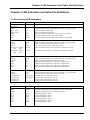
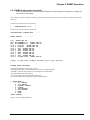
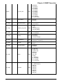
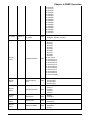
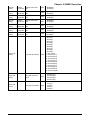
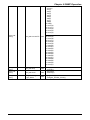
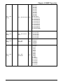
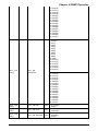
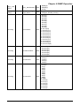
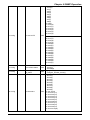
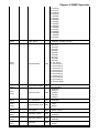
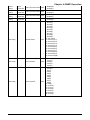
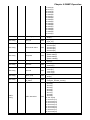
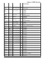
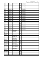
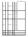
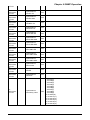
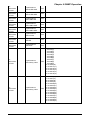
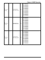
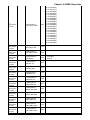
Chapter 9 SNMP Operation
e1performanc
e-E1B1
e1performanc
e-E1B1
e1performanc
e-E1B1
e1-performanceE1B1-history-index
RW
31: record31(31)
32: record32(32)
33: record33(33)
34: record34(34)
35: record35(35)
36: record36(36)
37: record37(37)
38: record38(38)
39: record39(39)
40: record40(40)
41: record41(41)
42: record42(42)
43: record43(43)
44: record44(44)
45: record45(45)
RW
46: record46(46)
47: record47(17)
48: record48(48)
49: record49(49)
50: record50(50)
51: record51(51)
52: record52(52)
53: record53(53)
54: record54(54)
55: record55(55)
56: record56(56)
57: record57(57)
58: record58(58)
59: record59(59)
60: record60(60)
RW
61: record61(61)
62: record62(62)
63: record63(63)
64: record64(64)
65: record65(65)
66: record66(66)
67: record67(67)
68: record68(68)
69: record69(69)
70: record70(70)
71: record71(71)
72: record72(72)
73: record73(73)
74: record74(74)
75: record75(75)
108
Chapter 9 SNMP Operation
e1performanc
e-E1B1
e1performanc
e-E1B1
e1performanc
e-E1B1
e1performanc
e-E1B1
e1performanc
e-E1B2
e1performanc
e-E1B2
e1performanc
e-E1B2
e1performanc
e-E1B2
e1performanc
e-E1B2
e1performanc
e-E1B2
e1performanc
e-E1B2
e1performanc
e-E1B2
e1performanc
e-E1B2
e1performanc
e-E1B2
e1-performanceE1B1-history-index
RW
e1-performanceE1B1-history-ES
RO
e1-performanceE1B1-history-UAS
RO
e1-performanceE1B1-Reset
RW
e1-performanceE1B2-Err-Cnt
RO
e1-performanceE1B2-Err-Rate
RO
e1-performanceE1B2-BPV-Cnt
RO
e1-performanceE1B2-CRC-Cnt
RO
e1-performanceE1B2-CURR-ES
RO
e1-performanceE1B2-CURR-UAS
RO
e1-performanceE1B2-CURR-SEC
RO
e1-performanceE1B2-LONG-ES
RO
e1-performanceE1B2-LONG-UAS
RO
e1-performanceE1B2-LONG-SEC
RO
76: record76(76)
77: record77(77)
78: record78(78)
79: record79(79)
80: record80(80)
81: record81(81)
82: record82(82)
83: record83(83)
84: record84(84)
85: record85(85)
86: record86(86)
87: record87(87)
88: record88(88)
89: record89(89)
90: record90(90)
91: record91(91)
92: record92(92)
93: record93(93)
94: record94(94)
95: record95(95)
96: record96(96)
1: normal(0)
2: clear(1)
109
Chapter 9 SNMP Operation
e1performanc
e-E1B2
e1performanc
e-E1B2
e1performanc
e-E1B2
e1performanc
e-E1B2
e1performanc
e-E1B2
e1performanc
e-E1B2
e1-performanceE1B2-counter
RO
e1-performanceE1B2-ES
RO
e1-performanceE1B2-UAS
RO
e1-performanceE1B2-history-index
RW
1: record1(1)
2: record2(2)
3: record3(3)
4: record4(4)
5: record5(5)
6: record6(6)
7: record7(7)
8: record8(8)
9: record9(9)
10: record0(10)
11: record11(11)
12: record12(12)
13: record13(13)
14: record14(14)
15: record15(15)
RW
16: record6(16)
17: record7(17)
18: record8(18)
19: record9(19)
20: record20(20)
21: record21(21)
22: record22(22)
23: record23(23)
24: record24(24)
25: record25(25)
26: record26(26)
27: record27(27)
28: record28(28)
29: record29(29)
30: record30(30)
RW
31: record31(31)
32: record32(32)
33: record33(33)
34: record34(34)
35: record35(35)
36: record36(36)
37: record37(37)
38: record38(38)
39: record39(39)
40: record40(40)
41: record41(41)
42: record42(42)
43: record43(43)
44: record44(44)
45: record45(45)
110
Chapter 9 SNMP Operation
e1performanc
e-E1B2
e1performanc
e-E1B2
e1performanc
e-E1B2
e1performanc
e-E1B2
e1performanc
e-E1B2
e-E1B2
RW
46: record46(46)
47: record47(17)
48: record48(48)
49: record49(49)
50: record50(50)
51: record51(51)
52: record52(52)
53: record53(53)
54: record54(54)
55: record55(55)
56: record56(56)
57: record57(57)
58: record58(58)
59: record59(59)
60: record60(60)
RW
61: record61(61)
62: record62(62)
63: record63(63)
64: record64(64)
65: record65(65)
66: record66(66)
67: record67(67)
68: record68(68)
69: record69(69)
70: record70(70)
71: record71(71)
72: record72(72)
73: record73(73)
74: record74(74)
75: record75(75)
e1-performanceE1B2-history-index
RW
76: record76(76)
77: record77(77)
78: record78(78)
79: record79(79)
80: record80(80)
81: record81(81)
82: record82(82)
83: record83(83)
84: record84(84)
85: record85(85)
86: record86(86)
87: record87(87)
88: record88(88)
89: record89(89)
90: record90(90)
91: record91(91)
92: record92(92)
93: record93(93)
94: record94(94)
95: record95(95)
96: record96(96)
e1-performanceE1B2-history-ES
RO
e1-performanceE1B2-history-UAS
RO
e1-performanceE1B2-Reset
RW
`
e1-performanceE1B2-history-index
1: normal(0)
2: clear(1)
111
Chapter 9 SNMP Operation
Alarm messages for ERM-MUX/Plus SNMP
Alarm messages have the following format:
[Slot #] + [card type] + [channel] + [Alarm info] + [time] for example:
I/O Slot 8 FXS Plug_In Time 05.09.10.01.58.45
Slot
Card Type
Channel 1/2/3/4/5/6
E1A1/E1B1/E1A2/E1B2
Fan 1/2/3/4/5
Expansion Fan 1/2/3/4/5
Power A/B
Expansion Power A/B
DEFAULT
SYSTEM
CPU-A
CPU-B
E1-A
E1-B
I/O SLOT1
…
I/O SLOT10
EXPANSION I/O SLOT1
…
EXPANSION I/O SLOT10
DEFAULT
SNMP
FAN
POWER
CPU
2*E1
1*E1
N64K/V35
G703-64K
FXS
FXO
E&M
MGNTO
X.50
N64K/232
ET100*2
A/SYNC-128K
SUB E1 * 2
SYSTEM
DEFAULT
CHANNEL1/FAN1/E1A1/E1B1/PowerA
CHANNEL2/FAN2/E1A2/E1B2/PowerB
CHANNEL3/FAN3/Extend PowerA
CHANNEL4/FAN4/Extend PowerB
CHANNEL5/FAN5
CHANNEL6/Extend FAN1
CHANNEL7/Extend FAN2
CHANNEL8/Extend FAN3
CHANNEL9/Extend FAN4
CHANNEL10/Extend FAN5
112
Chapter 9 SNMP Operation
Alarm Information
Alarm Date-Time
TURN ON
TURN OFF
NORMAL
ALARM
SYNC
SYNC LOSS
SIGNAL NORMAL
SIGNAL LOSS
REMOTE SYNC
REMOTE SYNC LOSS
STOP WORKING
BACKUP WORKING
PLUG IN
PLUG OUT
CHANGE CARD
EXTERNAL CLOCK SIGNAL LOSS
EXTERNAL CLOCK SIGNAL NORMAL
AIS NORMAL
AIS ALARM
User login
MARK
SPACE
ALT
EMPTY
ACTIVE(FXS/FXO voice call)
Yymmddhhmmss
113
Appendix A
Appendix A Specifications of ET100 card
When the ERM-MUX/PLUS uses the ET100 card, it is not only a multifunctional TD-intercrossing multiplexer, but
also, a high performance 10/100M Ethernet Bridge over E1 LINK. The physical interface of ET100 is RJ-45 Ethernet.
Each card provides two ports. The rate of WAN in each port ranges from 64Kbps~1984Kbps and can be selected
according to user's needs when any E1 line of the device is linked. The rate of LAN is 10M/100M auto-negotiation, and
user can set to link HUB or PC without changing the cable (MDIX).
Features
LAN
10/100Mbps full-duplex/half-duplex
Support IEEE802.3 flow control
Auto-MDI/MDIX detects and corrects crossed cable
256 MAC address with 5 minute automatic aging
Auto-address update
Up to 340 packages buffer
WAN
Support HDLC protocol.
Sending data follows external E1 clock.
Provide loop test function.
Rate is assigned according to user need.
Illustration of LED Indicators:
Name
Color
PWR
Alarm
Link status
ERR
DP_STAT
Speed
WRXD
WTXD
green
red
yellow
yellow
green
green
green
green
Descriptions
Light on-indicates Card power normal, off - Card power fault
Light on-indicates Card alarm, off – normal
Light on-indicates linked, off - not linked
Light on-indicates some error event happened, off - normal
Light on-indicates full-duplex, off - half-duplex
Light on-100M. off - 10M
Light on-receive data from WAN, off- line is idle.
Light on- transmit data from WAN, off- line is idle.
Interface and Cable
Ethernet LAN Interface on RJ-45 connecter
ET100 port provides Auto MDIX, using direct connect cable to PC or HUB.
RJ-45 Pins assignment: Pin 1,2 TD+ TD-, Pin 3,6 RD+ RD-.
Notice: When select MDI mode (SW1-1 at OFF state):
Cable connecting to PC must be direct cable, and cable to HUB must be crossed cable.
114
Appendix A
Configuration
Hardware setting
Auto-MDI/MDIX Setting
SW1-1
Description
ON
Auto-MDI/MDIX mode
OFF
MDI mode
Memory Settings
SW1-2
ON
ON
OFF
OFF
SW1-3
ON
OFF
ON
OFF
Description
LAN TO WAN 308 packages, WAN TO LAN 32 packages.
LAN TO WAN 170 packages, WAN TO LAN 170 packages.
LAN TO WAN 32 packages, WAN TO LAN 320 packages.
No defined.
SW1-4: No defined.
Parameters setting by Monitor menu or NMP Management
Auto-Negotiation.
Communication Speed: 10Mor100M
Flow Control.
Mac Filtering.
Communication Mode: Full/Half duplex.
Local Loop(only for manufacturer testing).
E1 channel selection.
E1 Time slots selection
ET100 Monitor menu setup
Set ET100 card
Selecting one ET100 card, it displays the current configuration and status information of the N64K/V35 card selected.
slot 04 ET100 card STATE:NORMAL
It shows the slot number, card type, and card status
CH1:NOE1:NULL,ANEG ENABLE,FULL,100M,FLOW CONTROL DISABLE,AUTO MAC ENABLE,NOLOOP
CH2:NOE1:NULL,ANE ENABLE,FULL,100M,FLOW CONTROL DISABLE,AUTO MAC ENABLE,NOLOOP
It shows the status of each channel, including multiplexed E1 channel, timeslot, ANEG or not, full/half
duplex,10M/100M,flow control or not, auto MAC or not, loop mode.
ET100 Menu Display
<< I/O CONFIG-ET100 >>
1. CH1
2. CH2
Set channel 1
Set channel 2
0. EXIT
Return to the input box of I/O card
configuration
INPUT SELECT:1
Press 0 or ESC to return to the I/O card selection menu, Press 1-2 to enter ET100 channel configuration (the same
configuration menu applies for both channels, 1 and 2).
115
Appendix A
ET100 Channel Menu Display
Select a channel, say channel 1, and enter configuration menu, the menu displays:
<< IO CONFIG-ET100-CHANNEL 1 >>
1.CONNECT E1
2.CONNECT TIMESLOT
3. Auto-Negotiation
4. Communication Mode
5. Speed
6. Flow Control
7. Mac Filtering
8. Local Loop
0.EXIT
INPUT SELECT:
Set multiplex E1 channel
Set multiplex timeslot
Set ANEG
Set Full/Half duplex
Set 10M/100M
Set Flow control
Set Auto MAC
Set Local Loop(only for manufacturer testing)
Return to the upper menu
Press 0 or ESC to return to the upper menu, and press 1-8 to enter the corresponding configuration.
Set multiplex E1 number
Press 1 to enter the configuration menu of setting E1 channel. The menu displays:
<< IO CONFIG-ET100-CHANNEL 1-E1 >>
*1.
2.
3.
4.
DISABLE
E1A1
E1A2
E1B1
No multiplexing
Multiplexing from E1A1
Multiplexing from E1A2
Multiplexing from E1B1
5. E1B2
Multiplexing from E1B2
0. EXIT
Return to the upper menu
INPUT SELECT:
('*'indicates the current setting.)
Press number 1 to 5 to configure and press 0 or ESC to return to the upper menu. After selecting a number, the menu
will refresh, and '*' will indicate the new settings.
Set multiplex timeslot
Press 2 to configure multiplex timeslot, if users do not set any E1 channel connection, then the system displays:
PLEASE CHOOSE CONNECT E1 FIRST!
If any E1 channel connection has been set, say E1A1, then the system displays the idle timeslots of all E1 channels.
FREE TIMESLOT IS:
E1A1: 01-30,
E1A2: 01-31,
E1B1: 01-31,
E1B2: 01-31,
It also displays the current status that there is no timeslot connection from E1A1.
CURRENT:E1A1-NULL
INPUT EXAMPLE: 3-9,11
INPUT TIMESLOT:
One or more than one idle timeslots can be assigned to one channel:
You can assign one single timeslot number or consecutive timeslot numbers. For example, 5,10-20,27 means the
timeslots 5, 10 to 20, and 27 of E1A1 (selected earlier) are assigned to CH1.
Input the idle timeslot number and press Enter to confirm. Return to the upper menu. If the input timeslot is being used
then the system prompts:
THE TIMESLOT ALREADY USED!
INPUT AGAIN!
116
Appendix A
INPUT TIMESLOT
If no timeslot number has been input, then press Enter or ESC return to the upper menu.
Set Auto-Negotiation mode
Press 3 to set Auto-Negotiation mode, the menu displays
<< I/O CONFIG-ET100-CHANNEL 1-ANEG >>
Auto Enable
Auto Disable
Return to the upper
*1. ENABLE
2. DISABLE
0. EXIT
INPUT SELECT:0
('*'indicates the current setting.)
Press 1 or 2 to select configuration, and press 0 or ESC to return to the upper menu. The system will refresh the display,
and '*' will indicate the new setting.
Set Work mode
Press 4 to set Work mode, the menu displays
<< I/O CONFIG-ET100-CHANNEL 1-DPLEX >>
*1. FULL
2. HALF
Full duplex
Half duplex
0. EXIT
INPUT SELECT:0
Return to the upper menu
('*'indicates the current setting.)
Press 1 or 2 to select configuration, and press 0 or ESC to return to the upper menu. The system will refresh the display,
and '*' will indicate the new setting.
Set Speed
Press 5 to set Speed, the menu displays
<< I/O CONFIG-ET100-CHANNEL 1-SPEED >>
*1. 100M
2. 10M
100BASE-TX
10BASE-T
0. EXIT
INPUT SELECT:0
Return to the upper menu
('*'indicates the current setting.)
Press 1 or 2 to select configuration, and press 0 or ESC to return to the upper menu. The system will refresh the display,
and '*' will indicate the new setting.
Set Flow Control mode
Press 6 to set Flow Control mode, the menu displays
<< I/O CONFIG-ET100-CHANNEL 1-FLOW CONTROL >>
Without Flow Control
With Flow Control
Return to the upper menu
*1. DISABLE
2. ENABLE
0. EXIT
INPUT SELECT:0
('*'indicates the current setting.)
Press 1 or 2 to select configuration, and press 0 or ESC to return to the upper menu. The system will refresh the display,
and '*' will indicate the new setting.
117
Appendix A
Set Auto MAC mode (filtering)
Press 7 to set Auto MAC mode, the menu displays
<< I/O CONFIG-ET100-CHANNEL 1-AUTO MAC >>
Without Auto MAC
With Auto MAC
Return to the upper menu
*1. DISABLE
2. ENABLE
0. EXIT
INPUT SELECT:0
('*'indicates the current setting.)
Press 1 or 2 to select configuration, and press 0 or ESC to return to the upper menu. The system will refresh the display,
and '*' will indicate the new setting.
Set loop mode
Press 8 to set loop mode, the menu displays
<< IO CONFIG- ET100-CHANNEL 1-LOOPBACK >>
With loop
Without loop
Return to the upper menu
*1. LOOP
2. NORMAL
0. EXIT
INPUT SELECT:0
('*'indicates the current setting.)
Press 1 or 2 to select configuration, and press 0 or ESC to return to the upper menu. The system will refresh the display,
and '*' will indicate the new setting.
118
Appendix B
Appendix B Specifications of Expansion Chassis
B-1 Introduction
If the ports on all the I/O cards are not enough, extension chassis can be used. It can extend IO card to 20 slots, voice
channel can be extended up to 120.
There is no need to insert CPU or E1 cards in the expansion chassis, but power modules are required, and those external
clock interface, SNMP input, two ends of RS-485 and major/ minor alarm contact points on its backplane cannot be
used.
For the device management, system uses the main chassis and expansion chassis as one device and supports either
terminal or NMP/SNMP management mode. MUX-PLUS main chassis can have only one expansion chassis.
The connection to expansion chassis
1. Connect main chassis to expansion chassis by HDB62 expansion chassis signal cable. Cable connector is on the
backplane as following Fig B1 (cable pin assignment see section 4).
2. Confirm no CPU or E1 cards are in expansion chassis.
3. Power on without regard to sequence; however it is suggested to switch on the main chassis first.
4. Set the parameters for each port to start work of expansion chassis. (see section 3).
Fig B1 Connections on backplane
119
Appendix B
B-2 Settings for Extension Case by Terminal
After power on, system displays on screen
<< MAIN MENU >>
1. E1 CONFIG
2. I/O CONFIG
3. DISPLAY CONFIG
4. CONFIG
5. SET DEFAULT
6. SET SYSTEM
0. EXIT
Select 2, displays:
INPUT SELECT:2
IO CONFIG
SEARCH.....
BOARD NO:1,4,5,6,7,8,9,10,17(E-1),19(E-3),20(E-4),21(E-5),23(E-7),26(E-10)
INPUT BOARD NO: 26
EXTEND slot 10 N64/V35
STAT:NORMAL
CH1:E1A1:1-30 ,DCE,INTERNAL CLOCK,NOLOOP
CH2:E1A2:1-31,DCE,INTERNAL CLOCK,NOLOOP
CH3:E1B1:1-31,DCE,INTERNAL CLOCK,NOLOOP
CH4:E1B2:1-31,DCE,INTERNAL CLOCK,NOLOOP
Next settings is as same as the main case.
Note: In the expansion chassis, the first slot displays 17(E-1), second slot, 18 (E-2), and so on up to 26 (E-10) which
means the expansion chassis slot 10.
For example:
To set slot 1, enter 17.
To set slot 2, enter 18.
To set slot 3, enter 19.
In turn, enter 26 to set slot 10 in expansion chassis. The settings of other parameters are the same as with the main
chassis.
120
Appendix B
DB62 Cable Pins and Definitions Table (male to male)
62 core pins allocations
1
2
3
4
5
6
62 core pins allocations
1
2
3
4
5
6
Definitions
signal
signal
(GND)
signal
signal
(GND)
7
8
7
8
signal
(GND)
twisted-pair
9
10
9
10
signal
(GND)
twisted-pair
11
12
11
12
signal
(GND)
twisted-pair
13
14
13
14
signal
(GND)
twisted-pair
15
16
17
15
16
17
signal
(GND)
signal
single
twisted-pair
18
19
41
18
19
41
signal
(GND)
signal
single
twisted-pair
21
22
23
44
21
22
23
44
signal
signal
signal
(GND)
single
single
twisted-pair
24
45
24
45
(GND)
signal
twisted-pair
25
46
25
46
signal
(GND)
twisted-pair
26
47
26
47
(GND)
signal
twisted-pair
27
48
27
48
signal
(GND)
twisted-pair
28
49
28
49
(GND)
signal
twisted-pair
29
50
29
50
signal
(GND)
twisted-pair
30
51
30
51
(GND)
signal
twisted-pair
31
52
31
52
signal
(GND)
twisted-pair
32
53
32
53
(GND)
signal
twisted-pair
33
54
33
54
signal
(GND)
twisted-pair
34
55
34
55
GND)
signal
twisted-pair
35
56
35
56
signal
(GND)
twisted-pair
36
57
36
57
(GND)
signal
twisted-pair
37
58
37
58
signal
(GND)
twisted-pair
38
59
38
59
(GND)
signal
twisted-pair
39
60
39
60
signal
(GND)
twisted-pair
40
61
40
61
(GND)
signal
twisted-pair
42
43
62
42
43
62
signal
signal
signal
single
single
single
Note 1:PIN20 has no connection.
Note 2:The length of cable should not be longer than 0.5m
121
single
twisted-pair
single
twisted-pair
Appendix C
Appendix C Specifications of NMP
Specifications of NMP Network Management Functional Extension and Multiple Chassis application
C-1 Connecting NMP network management access
The NMP network management system can connect via local PC or from cascaded equipment such as the ETU-DXC or
other ERM-MUX/PLUS via E1 line. We refer to this as in-band network management mode. (See the Network
Management Protocol System Operational User Manual.)
Note: Before using NMP network functions, the ERM-MUX/PLUS must be configured with console terminal to select
the network management mode and other necessary settings. (See Chapter 5)
C-1.1 Local NMP network management
Connect the DB9 serial cable between the PC COM port and the CPU card's front panel NM Ctrl connecter.
Communication mode: RS-232 9600/8/N/1
RS-232 Pin assignment: 2-TXD, 3-RXD, 5-ground.
Using the RS-485 connecters (RJ-45x2) can extend management to multiple chassis.
Note: RJ-45 Pin assignment for RS-485: 1(+), 2(-) NMP RXD; 3(+), 4(-) NMP TXD; 7, 8 ground.
Multiple chassis RS485 links can only use from the top layer (parent) in the NMP network topology structure.
Fig 1
Notes:
1) When using double CPU cards, the CPU cards will work in Backup Mode automatically after power on, without any
other settings.
2) Local control serial console cable should connect to working CPU's port.
3) After setting by the terminal menu, in-band management will connect from E1A1 line to child device (only requires
one timeslot of E1 line) See fig 2.
Note: Only E1A1 line or its backup E1 line can connect with in-band NMP network management.
Fig 2
C-2. Adding MUX-PLUS Devices in NMP System
To add one MUX-PLUS device in NMP, configuration of the MUX-PLUS parameters in NMP system and local
terminal is needed. Please refer to the NMP Operation Users Guide.
C-3.1 NMP Configuration
Terminal configuration (definition for device address and NMP parent/child ports)
Connect the DB9 serial cable between the PC COM port and CPU module front panel LOC Ctrl connecter.
Communication settings: RS-232 9600/8/N/1
Run HyperTerminal on the PC.
Power on the MUX-PLUS and enter the main menu for device management.
First select menu items 6->3->3 to clear any previous NMP parameters.
In the main menu, select items 6->3->5, input MUX-PLUS address. (See 5.7.3.4)
C-3.2 Modify NMP up port (connected to a parent device)
When local MUX-PLUS device connects with NMP system directly by RS-232 port on the front panel, in the main
menu, select items 6-->3-->1-->1-->1 to define local NMP mode.
When MUX-PLUS device connects with NMP system by RS-485 port on the backplane, in main menu, select items 6->3-->1-->2-->1-->5. UP-485.
When MUX-PLUS device connects with NMP by E1 cable (in-band NMP), in main menu, select items 6-->3-->1-->2->1-->1/2/3/4 (corresponding to E1A1/E1A2/E1B1/E1B2), then enter the NMP timeslot.
Modify the NMP lower port (connected as a child device)
122
Appendix C
a. For the local device connected with NMP directly, in main menu, select items 6-->3-->1-->2-->1/2/3/4,
(corresponding to E1A1/E1A2/E1B1/E1B2), enter the lower NMP timeslot. if there is no child device, enter 0 to clear
the lower NMP timeslot.
b. For the device connected with NMP by other device, in main menu, select items 6-->3-->2-->2-->1/2/3/4
(corresponding to E1A1/E1A2/E1B1/E1B2), enter the lower NMP timeslot, if no child device, enter 0 to clear the lower
NMP timeslot.
Return to main menu and save all parameters. The configuration is finished.
C-3.3 Definition for device addresses and the port connected to NMP
MUX-PLUS connects to the NMP system by only one port.
Local device: the NM Ctrl port (DB9) on front panel of CPU module.
Non-local device: the port can be E1A1 (in-band) or RS-485.
Every MUX-PLUS address is generated by NMP system according to the parent device and the port connected to NMP.
The user can modify the MUX-PLUS device address according to the Address Protocol. However, we suggest that you
let the system auto-generating addresses, which is safer, and do not modify the addresses at random, unless the device
cannot connect with NMP system correctly.
MUX-PLUS device supports Tree mode and Linear mode in the network topology. According to Address Protocol:
In Linear mode, device address should be different only in last part (there are 4 parts in an address), and the address of
device farthest from NMP should be higher than that of device nearest NMP.
In Tree mode, the last part of address of up device should be smaller than that of lower or child device.
C-3.4 Connection of MUX-PLUS in NMP topology structure
1. Point to point connection of MUX-PLUS in NMP topology structure, with E1 line or multiple chassis RS-485 port.
PC
MUX- PLUS 1
E1/ RS485
MUX- PLUS
NMP/ SNMP
2. Liner mode connection of MUX-PLUS in NMP topology structure, with E1 line or multiple chassis RS-485 port,
Supports up to 48 nodes. The address for each device must be different.
P C
MUX- PLUS 1
NMP/ SNMP
E1
MUX- PLUS
E1
MUX- PLUS
RS485
MUX- PLUS
E1
MUX- PLUS
E1
MUX- PLUS
RS485
MUX- PLUS
E1
MUX- PLUS
123
E1
MUX- PLUS
Appendix C
3. Tree mode connection of MUX-PLUS in NMP topology structure, with E1 line or multiple chassis RS-485 port.
Supports up to 48 nodes. The address for each device must be different.
PC
MUX- PLUS 1
NMP/ SNMP
E1
MUX- PLUS
RS485
E1
MUX- PLUS
MUX- PLUS
MUX- PLUS
E1
MUX- PLUS
MUX- PLUS
MUX- PLUS
E1
MUX- PLUS
MUX- PLUS
RS485
MUX- PLUS
MUX- PLUS
E1
MUX- PLUS
C-4 Liner mode connection of MUX-PLUS combined with Tree mode NMP topology structure
PC
ETU/ ERM- DXC
LEVEL 1
NMP
E1
E1
ETU/ ERM- MUX
LEVEL 1
ETU/ ERM- DXC
LEVEL 2
ETU/ ERM- DXC
LEVEL 2
E1
ETU/ ERM- DXC
LEVEL 3
MUX- PLUS l i ner
sect i on LEVEL 1
E1
ETU/ ERM- MUX
LEVEL 2
ETU/ ERM- DXC
LEVEL 3
ETU/ ERM- MUX
LEVEL 1
ETU/ ERM- MUX
LEVEL 2
MUX- PLUSl i ner
sect i on LEVEL 2
E1
ETU/ ERM- MUX
LEVEL 3
ETU/ ERM- MUX
LEVEL 3
Supports up to 48 nodes. The address of each device must be different.
124
MUX- PLUS l i ner
sect i on LEVEL 3
Appendix D
Appendix D Basic Configuration
ERM-MUX-PLUS AC standard configurations list
Sequence
No.
1
Item
Host
Component name
Quantity
EMP-rack
EMP-MB
(motherboard)
EMP-AC power
module
EMP-ACV voice
power module
EMP-1xE1, single
E1 line module
EMP-2xE1, double
E1 line module
EMP-CPU control
module
EMP-C/B control
sub-card
Expansion chassis
Exp-C/B control
sub-card
1
multiple chassis
2
3
4
5
6
7
8
9
10
11
Optional
module
G703-EXTCLK
EMP-N64K/V.35
module
EMP-A/SYNC128K module
EMP-G703-64K
module
EMP-MAGNETO
module
EMP-FSO voice
module
EMP-FXS voice
module
EMP-E&M voice
module
EMP-ET100 LAN
module
EMP-X50 module
EMP-SUBE1
module
1
Attached cable
Number of
cables
Power cord
1
1 or 2
1 or 2
2 cables for
one E1 line
2 cables for
one E1 line
1 or 2
BNC cable
1 or 2
BNC cable
1 or 2
DB9 (male) /DB9 (female) directconnected cable
1
DB62(male)/ DB62(male)cable
1
1
1
according
to user
RJ45 cable
BNC cable
according to
user
1
HP68 (male)/4XV35 (female)cable
DB62 (male) /6XDB25 (female)
cable
6XRJ45 cable
6X RJ45/RJ11 cable
6X RJ45/RJ11 cable
6X RJ45/RJ11 cable
6X RJ45 cable
2X RJ45 cable
DB62(male)/5XDB25(female)cable
BNC cable
125
Cables can be
provided
according to
user
requirements
Appendix E
Appendix E Firmware upgrade
The setting of TCP/IP after CPU firmware upgrade
After upgrading the firmware of the CPU, the CPU version will not be shown until the next log in. Press "3" will go into
the TCP/IP setting. An example shown below and those values will help you to finish the TCP/IP setting. To bypass any
parameter entry, press "n" to go to the next setting and press "back space" to delete any characters you may have typed
in error. When doing the TCP/IP settings, the MAC address is in hexadecimal format after version V2.01. All other
numbers in TCP/IP settings are decimal format. Please keep that in mind when you are doing the TCP/IP setting.
Key-in example:
CURRENT MAC ADDR:.7B.0A.78.7B.16.D5
INPUT NEW MAC ADDR:7Dn
INPUT ERR,INPUT AGAIN!
INPUT NEW MAC ADDR:7D.0A.24.3D.42.D2
CURRENT MAC ADDR:.7d.0a.24.3d.42.d2
CURRENT IP ADDR:.192.168.010.110
INPUT NEW IP ADDR:n
CURRENT SUBNET MASK:.255.255.255.000
INPUT NEW SUBNET MASK:n
CURRENT GATEWAY IP:.202.100.064.068
INPUT NEW GATEWAY IP:n
CURRENT TFTP SERVER IP:.202.102.010.010
INPUT NEW TFTP SERVER IP:n
CURRENT TFTP PATH:
INPUT NEW TFTP PATH:N
CURRENT COMMUNITY RD/WR:00000000
INPUT NEW COMMUNITY RD/WR:N
CURRENT COMMUNITY RD ONLY:00000000
INPUT NEW COMMUNITY RD ONLY:Public
CURRENT COMMUNITY RD ONLY:Public
CURRENT ACCESS IP ADDR #1:.000.000.000.000
INPUT NEW ACCESS IP ADDR #1:192.168.10.4
CURRENT ACCESS IP ADDR #1:.192.168.010.004
CURRENT ACCESS IP ADDR #2:.000.000.000.000
INPUT NEW ACCESS IP ADDR #2:192.168.10.5
CURRENT ACCESS IP ADDR #2:.192.168.010.005
CURRENT ACCESS IP ADDR #3:.000.000.000.000
INPUT NEW ACCESS IP ADDR #3:192.168.10.6
CURRENT ACCESS IP ADDR #3:.192.168.010.006
CURRENT ACCESS IP ADDR #4:.000.000.000.000
INPUT NEW ACCESS IP ADDR #4:198.168.10.7
CURRENT ACCESS IP ADDR #4:.198.168.010.007
CURRENT TELNET MANAGER:0000
INPUT NEW TELNET MANAGER:Admin
INPUT TOO LONG,INPUT AGAIN!
INPUT NEW TELNET MANAGER:User
CURRENT TELNET MANAGER:User
CURRENT TELNET PASSWORD:0000
INPUT NEW TELNET PASSWORD:user
CURRENT TELNET PASSWORD:user
Press the "Enter" or "ESC" key to skip all setting and go back to previous page of "NMP/SNMP"
126
Appendix F
Appendix F Version II NMP/SNMP functions
F-1 Additional functions for Version II NMP/SNMP
(The additional functions below only show the difference in Version II, otherwise everything else is the same as with
Version I module)
In the system menu, press "6" button to go into the menu.
<< SYSTEM MENU >>
1. VERSION
2. CLOCK
3. NMP MODE
4. E1 BACKUP
5. CHANGE PASSWORD
6. SETUP TIME
7. SETUP EXTEND BOX
0. EXIT
INPUT SELECT:1
To show the version info.
To modify system clock.
To modify the management parameters of NMP/SNMP
To modify the backup mode of E1 module
To change password
To setup the system time
To setup expansion chassis
Press 0 to exit
All the following menus in this appendix deal with the management of expansion chassis. The "Up" refers to the parent
equipment where management is passed from and the "Down" refers to child equipment that has management passed to
it.
F-2. NMP / SNMP management parameters
From the main menu press "3", to enter the NMP/SNMP setting menu:
NMP MODE:MAJOR
UP:NMP
OWN:E1A1:NULL E1A2:NULL E1B1:NULL E1B2:NULL
<< SYSTEM CONFIG-NMP MODE >>
Descriptions
*1. MAJOR JOINT
Major Joint
2. SUB JOINT
Sub Joint
3.
4.
5.
0.
Disable NMP management function
Modify the TCP/IP setting of SNMP agent
Modify the hardware address setting
Press 0 to exit
DISABLE NMP
IP ADDRESS
DEVICE ADDRESS
EXIT
INPUT SELECT:1
Select 1 through 5 to go into the setting, or press 0, Enter or ESC key to get back the upper pages
F-3. The system configuration of NMP mode
In NMP/SNMP menu, press 1 to modify the system config-nmp mode-major.
<<SYSTEM CONFIG-NMP MODE-MAJOR >>
*1. UP
2. DOWN
0. EXIT
INPUT SELECT:1
Network management channel (Up channel)
Network management channel (Down
channel)
Press 0 to exit
Press 1 or 2 to go into the sub-menu
Or press 0, Enter or ESC to go back to the upper menu
127
Appendix F
F-3-1 System config-nmp mode-major-up setting
In "SYSTEM CONFIG-NMP MODE-MAJOR" menu, press 1 for "up channel sub-menu"
<< SYSTEM CONFIG-NMP MODE-MAJOR-UP >>
*1. LOCAL NMP
2. SNMP
0. EXIT
INPUT SELECT:1
Local NMP setting
The SNMP setting
Press 0 to exit
Press 1 for local NMP setting, press 2 for SNMP setting; Or press 0, Enter or ESC to go to upper menu
F-3-2 SYSTEM CONFIG-NMP MODE-MAJOR-DOWND setting
In "SYSTEM CONFIG-NMP MODE-MAJOR" menu press 2 for "SYSTEM CONFIG-NMP MODE-MAJORDOWND"
<< SYSTEM
*1. DOWN1
2. DOWN2
3. DOWN3
4. DOWN4
CONFIG-NMP MODE-MAJOR-DOWND >>
E1A1
E1A2
E1B1
E1B2
E1A1 Down
E1A2 Down
E1B1 Down
E1B2 Down
Press 0 to exit
0. EXIT
INPUT SELECT:1
Press 1 to 4 to go into the submenu, the following example is shown when pressing 2:
FREE TIMESLOT IS:
E1A2: 1-15,17-31,
CURRENT:E1A2-NULL
INPUT TIMESLOT(INPUT 0 TO CANCLE):31;
Press 0, Enter or ESC to go to the upper menu
F-4 "SYSTEM CONFIG-NMP MODE-MAJOR" setting
In NMP/SNMP menu, press 2 to modify the "SYSTEM CONFIG-NMP MODE-MAJOR"
<<SYSTEM CONFIG-NMP MODE-MAJOR >>
*1. UP
Network management up channel
2. DOWN
Network management down channel
0. EXIT
Press 0 to exit
INPUT SELECT:1
Press 1 to 2 to go into the submenu, press 0, Enter or ESC to go upper menu
128
Appendix F
F-4-1 "SYSTEM CONFIG-NMP MODE-SUB-UP" setting
In "SYSTEM CONFIG-NMP MODE-SUB" menu press 1 for "SYSTEM CONFIG-NMP MODE-SUB-UP", parameters
below:
<< SYSTEM CONFIG-NMP MODE-SUB-UP >>
1. UP E1A1
2. UP E1A2
3. UP E1B1
4. UP E1B2
5. UP 485
0. EXIT
INPUT SELECT:1
E1A1 Up
E1A2 Up
E1B1 Up
E1B2 Up
RS-485 Up
Press 0 to exit
Press 1 to 4 to go into the submenu, when press 2 shown below:
FREE TIMESLOT IS:
E1A2: 1-15,17-31,
CURRENT:E1A2-NULL
INPUT TIMESLOT(INPUT 0 TO CANCEL):31;
Press 0, Enter or ESC to go upper menu
F-4-2 "SYSTEM CONFIG-NMP MODE-SUB-DOWN" setting
In "SYSTEM CONFIG-NMP MODE-SUB " menu press 2 for "SYSTEM CONFIG-NMP MODE-MAJORDOWND" setting
<< SYSTEM CONFIG-NMP MODE-MAJOR-DOWND >>
*1. DOWN1 E1A1
E1A1Down
E1A2Down
E1B1Down
2. DOWN2 E1A2
3. DOWN3 E1B1
E1B2Down
Press 0 to exit
4. DOWN4 E1B2
0. EXIT
INPUT SELECT:1
Press 1 to 4 to go into the submenu, when press 2 shown below:
FREE TIMESLOT IS:
E1A2: 1-15,17-31,
CURRENT:E1A2-NULL
INPUT TIMESLOT(INPUT 0 TO CANCLE):31;
Press 0, Enter or ESC to go to the upper menu
F-5 ADD / DELETE expansion rack
In normal situation, the CPU will not detect if there is an extension rack or not. When adding a new ERM-MUX-plus
rack as an expansion rack, you need to do the proper setting to add an expansion rack.
In system menu, press 3 to show if there were an extension rack there. To add / delete extension rack:
CURRENT EXTEND BOX STATE:NO
ADD(A) OR DELETE(D) EXTERN BOX
PLEASE INPUT:
129
Appendix F
F-6 A new status display for IO card
6.1 There are new added statuses LEDs for N64/V35 and A/SYNC-128 cards in each direction. Those LEDs are
MARK, SPACE and ALT.
Example:
SLOT 01 A/SYNC-128K LINE 1 MARK (TD)
SLOT 01 A/SYNC-128K LINE 1 MARK (RD)
SLOT 01 A/SYNC-128K LINE 5 ALT (TD)
SLOT 01 A/SYNC-128K LINE 5 ALT (RD)
SLOT 01 A/SYNC-128K LINE 3 ALT (TD)
SLOT 01 A/SYNC-128K LINE 3 ALT (RD)
SLOT 02 N64/V35 LINE 1 ALT (RD)
SLOT 02 N64/V35 LINE 1 MARK (RD)
SLOT 02 N64/V35 LINE 4 ALT (RD)
SLOT 02 N64/V35 LINE 4 MARK (RD)
There are new added statuses LEDs for FXS/FXO card. Those LEDs are Normal, Active and alarm.
Example:
SLOT 05
SLOT 05
SLOT 05
SLOT 05
SLOT 05
SLOT 05
SLOT 05
SLOT 07
SLOT 07
SLOT 07
SLOT 07
SLOT 07
SLOT 07
SLOT 07
FXS
FXS
FXS
FXS
FXS
FXS
FXS
FXO
FXO
FXO
FXO
FXO
FXO
FXO
NORMAL
LINE 1
LINE 2
LINE 3
LINE 4
LINE 5
LINE 6
NORMAL
LINE 1
LINE 2
LINE 3
LINE 4
LINE 5
LINE 6
NORMAL
NORMAL
NORMAL
NORMAL
NORMAL
NORMAL
NORMAL
NORMAL
NORMAL
NORMAL
NORMAL
NORMAL
130
Appendix G
Appendix G New released functions for E1 module
The new release Error and Performance function for E1 module
G-1 The functions of BERT
<< MAIN MENU >>
1. E1 CONFIG
2. I/O CONFIG
3. DISPLAY CONFIG
4. CONFIG
5. SET DEFAULT
6. SET SYSTEM
7. BERT
0. EXIT
INPUT SELECT:
The configuration of E1 module
Retrieve and modify I/0 card setting
Display the configuration
Save and configure the system parameters
Restore all the parameters back to factory default
Retrieve and modify the system setting
Bit-error-rate test function
exit
Select 1 through 7 to go into the relative function
Select 7 to go into BERT test function
Press 0 or ESC key to go back to the upper page
G-2 BERT functions
<< BERT TEST >>
1. FUNCTION
2. CHANNEL
3. PATTERN
4. ERROR INSERT
5. RESULT
0. EXIT
INPUT SELECT:1
Start / Stop BERT test
Modify the E1 channel which will be tested
Setup the test pattern
Insert error codes into the E1 trunk
Test result
Back to the main menu
Press 0 or ESC, to go back to the main menu
Press 1 through 5 to enter the sub-menu
G-3 Start / Stop BERT testing
<< FUNCTION >>
Description
1. STOP
2. START/RESTART
0. EXIT
INPUT SELECT:
To stop the BERT testing
To start or restart the BERT testing
Back to the upper menu
Press 0 or ESC, to go back to the upper menu
Press 1 or 2 to select the test function
Note: The E1 performance monitoring is always on and can not be turned off.
131
Appendix G
G-4 Channel selection
When select the E1 channel which will be tested, please refer to your actual configuration.
Only one E1 module shown below:
<< CHANNEL >>
1. E1A1
Select the first E1 channel of the first E1 module
2. E1A2
Select the second E1 channel of the first E1 module
0. EXIT
Back to the upper page
INPUT SELECT:1
Press 0 or ESC, to go back to the upper menu
Press 1 or 2 to select the E1 channel will be tested
Note: The E1 performance monitoring is always on, can not be off.
Two E1 modules with single channel shown below:
<< CHANNEL >>
1. E1A1
Select the first E1 module
2. E1B1
Select the second E1 module
0. EXIT
Back to the upper page
INPUT SELECT:1
Press 0 or ESC, to go back to the upper menu
Press 1 or 2 to select the E1 channel will be tested
Two E1 modules and two channels shown below:
<< CHANNEL >>
1. E1A1
Select the first E1 channel of the first E1 module
2. E1A2
Select the second E1 channel of the first E1 module
3. E1B1
Select the first E1 channel of the second E1 module
4. E1B2
Select the second E1 channel of the second E1 module
0. EXIT
Back to the upper page
INPUT SELECT:1
Press 0 or ESC, to go back to the upper menu
Press 1 through 4 to select the E1 channel will be tested
G-5 Test pattern selection
Choose the appropriate test pattern
<< PATTERN >>
1. 2^9-1
2. 2^11-1
3. 2^15-1
4. QRSS
5. ALL 0
6. ALL 1
7. ALT
8. 3 IN 24
9. 1 IN 16
A. 1 IN 8
B. 1 IN 4
0. EXIT
INPUT SELECT: 1
The 2^9-1 test pattern
The 2^11-1 test pattern
The 2^15-1 test pattern
The QRSS test pattern
The ALL 0 test pattern
The ALL 1 test pattern
The ALT test pattern
The 3 IN 24 test pattern
The 1 IN 16 test pattern
The 1 IN 8 test pattern
The 1 IN 4 test pattern
Back to upper page
Press 0 or ESC, to go back to the upper menu
Press 1 through B to select the test pattern will be sent
132
Appendix G
G-6 Bit error rate insertion
<< ERROR INSERT >>
1. NONE
2. SINGLE
3. 1E-1
4. 1E-2
5. 1E-3
6. 1E-4
7. 1E-5
8. 1E-6
9. 1E-7
0. EXIT
INPUT SELECT:
None of error inserts
Insert just one error
Insert 1E-1 errors into the E1 link
Insert 1E-2 errors into the E1 link
Insert 1E-3 errors into the E1 link
Insert 1E-4 errors into the E1 link
Insert 1E-5 errors into the E1 link
Insert 1E-6 errors into the E1 link
Insert 1E-7 errors into the E1 link
Back to upper page
Press 0 or ESC, to go back to the upper menu
Press 1 through 9 to select the bit-error-rate will be sent
G-7 Display performance and test result of the E1 link
E1A1 PERFORMANCE
Bipolar violations count(BPV):
Current CRC-4 error count:
Current errored seconds(ES):
Current unavailable seconds(UAS):
Current Seconds(SEC):
Long-term errored seconds(LES):
Long-term unavailable seconds(LUAS):
Long-term seconds(LSEC):
OLD Current errored seconds(ES):
OLD Current unavailable seconds(UAS):
BIT ERROR:
BIT ERROR RATE:
<ESC> <CR> CLEAR. <SPACE> REFRESH.
Press ESC to back to upper page
Press <CR> to clear the result
133
0
0
0
0
0
0
0
0
0
0
0
0
E1 Transmission Series
CTC Union Technologies Co., Ltd.
Far Eastern Vienna Technology Center
(Neihu Technology Park)
8F, No.60, Zhouzi Street
Neihu, Taipei, Taiwan
Phone:(886) 2.2659.1021 Fax:(886) 2.2799.1355
E-mail: [email protected] http://www.ctcu.com