1
22.3
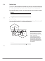
Replacing a CAN-Bus Device
Follow these instructions to replace a CAN-Bus device.
1.
2.
3.
4.
5.
6.
7.
8.
22.4
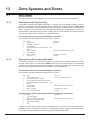
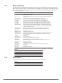
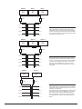
Note the node number of the CAN-Bus device that needs to be replaced.
On the S3 Control Unit locate the CAN-Bus device that need to be replaced in the
Parameters/Ports list. The device is listed under its node number. If the S3 can’t
communicate with the device the device should be marked with an X
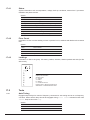
Press the right button on the S3 keypad to display the Cut and Paste menu.
To copy the settings of the device chose Cut
Return to the Parameters/Ports list and select the new device. The new device
should be marked with a ?
Press the right button on the S3 keypad to display the Cut and Paste menu.
To paste the settings of the old device onto the new device chose Paste
Restart the system
Adding a new CAN-Bus Device
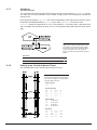
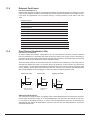
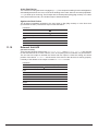
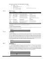
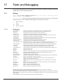
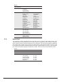
Buttons and I/O cards are programmed the same way as I/O ports on the S3 Control Unit. For
FloorIndicatorsthefloortheindicatorisinstalledonischosen(floordesignationsareprogrammed
under the Parameters/Indicators menu). Master buttons are listed under their unique node
number and the slave buttons are listed under the master button, where the action of the button is
configured.Slavebuttonscanbereplacedwithouttheneedforareset.
22.4.1
Programming a Button (S4-PB05)
1.
2.
3.
4.
5.
6.
7.
8.
22.4.2
Programming an I/O-card (S4-IO8)
1.
2.
3.
4.
5.
6.
7.
22.4.3
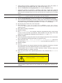
Connect the button to the CAN-Bus
On the S3 Control Unit locate the button in the Parameters/Ports list. The button is
listed under its node number and should be followed by a ?
Press enter to display the Configure Button Menu. SW1 is the master button and
SW2isthefirstslave-button,andsoon.
Select SW1 and press enter
Select Function and press enter
Select the desired function in the list
Program possible slave buttons on SW2-7
Reset the computer
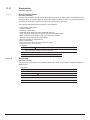
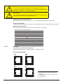
Connect the I/O-card to the CAN-Bus
On the S3 Control Unit locate the I/O-card in the Parameters/Ports list. The I/O-card
is listed under its node number and should be followed by a ?
Press enter to display the B11-18 Ports Menu. B11-18 represents the I/O ports of
the I/O card.
Select B11 and press enter
Select Function and press enter
Select the desired function in the list
Reset the computer
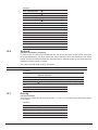
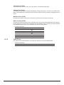
Programming a Floor Indicator (S3-DF03, S3-DF04, S4-MIO2, S4-MIO3)
1.
2.
3.
4.
5.
S3 Control Unit User Guide
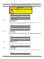
ConnectthefloorindicatortotheCAN-Bus
OntheS3ControlUnitlocatethefloorindicatorintheParameters/Ports list. The
floorindicatorislistedunderitsnodenumberandshouldbefollowedbya?
Press enter to display the Floor Menu.
Selectthefloorthefloorindicatorisinstalledonandpressenter
Reset the computer
63
Rev B2 - May 2009