1
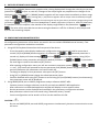
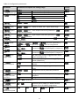
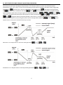
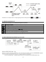
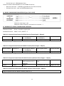
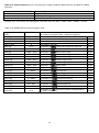
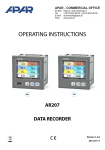
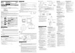
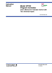
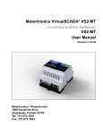
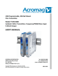
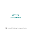
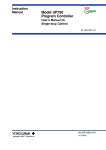
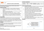
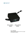
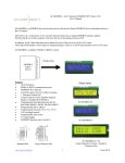
USER MANUAL PROCESS ANALOGUE CALIBRATOR AR904 Version 1.1.1 2013.02.13 Thank you for choosing our product. This user manual will help you with proper and safe operation and full use of the process analogue calibrator device. Before installing and operating, please read and understand this manual. If you have any additional questions, please contact the technical advisor. TABLE OF CONTENTS 1. 2. 3. 4. 5. 6. 7. 8. 9. 10. 11. 12. 13. 14. 15. 16. SAFETY PRECAUTIONS………………………………………………………………………………………… INSTALLATION NOTES…………………………………………………………………………………………. GENERAL PROCESS ANALOGUE CALIBRATOR CHARACTERISTICS………………………… PACKAGE CONTENTS………………………………………………………………………………………….. TECHNICAL DATA……………………………………………………………………………………………….. HOUSING DIMMENSIONS AND INSTALLATION DATA………………………………………….. TERMINAL STRIPS AND ELECTRICAL CONNECTIONS DESCRIPTION……………………… BUTTONS DESCRIPTION……………………………………………………………………………………… OUTPUT SETPOINT VALUE CHANGE……………………………………………………………………. CONFIGURATION PARAMETERS SETUP………………………………………………………………. SOFT START/STOP AND TRIANGLE WAVEFORM GENERATOR…………………………….. MESSAGES AND ERRORS LIST……………………………………………………………………………… RS485 COMMUNICATION INTERFACE (per EIA RS-485)………………………………………. RS232C COMMUNICATION INTERFACE (per EIA RS-232C)………………………………….. MODBUS-RTU SERIAL TRANSMISSION PROTOCOL……………………………………………… USER NOTES……………………………………………………………………………………………………….. 3 3 3 4 4 5 5 6 7 7 9 10 10 11 11 13 Pay special attention to information marked with this sign! Manufacturer reserves the right to make changes in design and software of the device without compromising technical parameters 2 1. SAFETY PRECAUTIONS Before using the unit, please read this manual carefully. To avoid electrical shock or damage to the device, mechanical and electrical installation have to be performed by a qualified personnel. Before turning on the power make sure that all cables are properly connected. Before making any modifications to the wiring connections, turn off all voltages applied to the device. You have to ensure proper working conditions, according to the specifications of the device (power supply voltage, humidity, temperature, chapter 5). 2. INSTALLATION NOTES This instrument was designed to provide the appropriate level of resistance to most disturbances that may occur in industrial environments. In environments with unknown level of interference it is recommended to use the following measures to prevent possible interference with operation of the instrument: Do not power supply the device from the same line as the power component without the appropriate network filters. Use only shielded power and signal cables taking into account that the grounding of the shield should be a single point, made as close to the device as possible. Avoid placing signal cables very close and parallel to energy and power cables. It is recommended to twist signal cables in pairs. Avoid proximity of remote controlled devices, electromagnetic meters, high power loads, loads with phase or group power control and other devices that generate large impulse disturbances. Ground or zero metal rails that are used to mount rail devices. Before using the device, remove the protective film from the LED display. 3. GENERAL PROCESS ANALOGUE CALIBRATOR CHARACTERISTICS This device allows you to control or test devices with current or voltage input (proportional valves, servomotors, inverters, motors, etc.) 2 analogue outputs (working simultaneously): - current 4÷20mA or 0÷20mA (active, cannot be powered from 2 wires current loop) - voltage 0÷10V Soft start/stop (ramping) or triangle wave generator with manual or automatic (activated after device power on) trigger. Programmable setpoint value, output signal change step, display range, soft start/stop options, communication options, access options and other configuration parameters. 7-segment LED display with brightness adjustment. Optional RS485/RS232 serial interface (galvanically isolated, MODBUS-RTU protocol). Parameters configuration methods: - Using IP65 foil keyboard located on the device front panel - Using AR955 programmer or RS485/RS232 interface with PC software (Windows 2000/XP/Vista/7) Available free software that allows parameters configuration. Access to configuration parameters can be password protected. High accuracy and high resistance to interference. 3 Available accessories: - AR955 programmer - RS485 to USB converter CAUTION: Before starting work with the process analogue calibrator, read this manual carefully and perform electrical and mechanical installation properly and set parameters correctly. 4. PACKAGE CONTENTS Process analogue calibrator User manual Warranty card 5. TECHNICAL DATA Analogue outputs Current (active) 0/4÷20mA (1) 2 3,8÷21mA / 0÷21mA / 21÷3,8mA, 21÷0mA R0 ≤ 1kΩ 1,7µA 0÷10,5V / 10,5÷0V R0 > 3,2kΩ (load current I0 < 4.5mA) 0,84mV Full range Load resistance Resolution (maximum) Voltage 0/2÷10V Full range Load resistance Resolution (maximum) Processing errors (ambient temperature 25C): Main: Additional from ambient temperature changes Output response time (10÷90%) RS485 communication Protocol interface Transmission speed Character format Galvanic isolation 7-segment LED display Number of digits Height Colour Power supply 230V AC 24V AC/DC (optional) Working conditions Working environment Protection level Weight Electromagnetic compatibility (EMC) 0,1% full output range ± 1 digit <0,005% output range / C 200ms MODBUS-RTU 2,4 ÷ 38,4kb/s 8N1 (no parity bit, 1 stop bit) 500V, 50Hz, 1 min 4 20mm Red (with brightness adjustment) 85 ÷ 260 V AC / 4VA 20 ÷ 50V AC / 4VA, 20 ÷ 72V DC / 4W 0 ÷ 50C, <90% RH (no condensation) Air and natural gases IP65 from front, IP20 from terminals ~160g Resistance: according to PN-EN 61000-6-2 Emissivity: according to PN-EN-61000-6-4 (1) - Output cannot be powered from two wires current loop 4 6. HOUSING DIMMENSIONS AND INSTALLATION DATA Housing type Material Housing dimensions Table window Fitting Panel, Incabox XT L57 Self-extinguishing NORYL 94V0, polycarbonate 96 x 48 x 79mm 92 x 46mm Brackets on housing sides 7. TERMINAL STRIPS AND ELECTRICAL CONNECTIONS DESCRIPTION Terminals 1-2 3-4 5-6-7 8-9 PRG Description Current output 0/4÷20mA Voltage output 0÷10V RS485/RS232 serial interface (MODBUS-RTU transmission protocol) Power supply input 230V AC or 24V AC/DC Programming socket for use with AR955 programmer (do not use simultaneously with RS485/RS232 interface) a) Terminals and output signals description CAUTION: Only AR955 programmer can be connected to PRG socket. Connecting other devices to PRG socket can damage connected device and AR904 process analogue calibrator. 5 8. BUTTONS DESCRIPTION a) Buttons functions in setpoint value display mode (normal mode) Button Description (and how they are marked in the manual) [UP] or [DOWN]: Output signal setpoint value increase or decrease by given step (parameter 6: , chapter 10) [SET] + [UP]: Step (fast) output signal setpoint value change – upper range value (parameter 3: ) or settings narrowing (5: ) [SET] + [DOWN]: Step (fast) output signal setpoint value change – lower range value (parameter 2: ) or settings narrowing (4: ) [UP] and [DOWN] (simultaneously): Opens parameters configuration menu (when pressed and hold for more than 1 second). If parameter 13: (password protection is turned on), you will have to enter protection password (chapter 10) [SET]: Soft start/stop function activation/deactivation (when pressed and hold for more than 1,5 second). If parameter 8: and 9: , function is inactive (chapter 11) b) Buttons functions in parameters configuration mode (chapter 10) Button Description [SET]: - Current parameter value change - Confirm and save modified parameter value [UP] or [DOWN]: - Go to the next or previous parameter - Change value of edited parameter [UP] and [DOWN] (simultaneously): - Cancel value change (return to parameter name display) - Return to setpoint value display mode (when pressed and hold longer than 0.5s) 6 9. OUTPUTS SETPOINT VALUE CHANGE Pressing [UP] or [DOWN] button while setpoint value is being displayed will change the value by pre-set step (parameter 6: , chapter 10, table 10). Changes of the output signal are proportional to changes of the displayed value. Pressing [SET] + [DOWN] buttons together will set output value immediately to lower range value (2: or 4: ) while pressing [SET] + [UP] buttons together will set output value immediately to upper range value (3: (parameter 7: or 5: ). In addition, the output signal may be given also in parameters programming mode ) and using serial interface RS485/RS232 or AR955 programmer (chapter 15, table 15). Moreover, it is possible to set the setpoint value outside of the display range based on the parameters 2: and 3: . The value of this override that can be set using the buttons is ±5% for 4÷20mA (2÷10V) output and 6,2% for the remaining outputs. 10. CONFIGURATION PARAMETERS SETUP All configuration parameters of the device are saved in the non-volatile EEPROM internal memory. Two parameters configuration methods are available: 1. Using IP65 foil keyboard located on the front panel of the device: - From the setpoint value display mode enter configuration menu (press and hold for more than 1 second [UP] and [DOWN] buttons together). If parameter 13: turned on), display will show message and then (password protection is with first digit blinking. Using [UP] or [DOWN] button enter protection password (by default parameter 12: the next digit or confirm the code use [SET] button. ). To proceed to - After opening configuration menu you will see mnemonic parameter names ( <-> <-> <-> etc.), [UP] button will proceed to the next parameter and [DOWN] button will go back to the previous parameter (all parameters are listed in table 10). - To change or display current parameter value press the [SET] button. - Using [UP] or [DOWN] button change the edited parameter value. - Confirm modified value using [SET] button or cancel using [UP] and [DOWN] buttons (simultaneously), then parameter name will be displayed. 2. Using RS485/RS232 port or AR955 programmer and pc software ARSOFT-WZ1: - Connect process analogue calibrator to the PC port and start ARSOFT-WZ1 application. - After connection is established application window will display current setpoint value. - Device parameters can be displayed and modified in the parameters configuration window. - New parameters values have to be saved using “Zatwierdź zmiany” button. - Current configuration can be saved in a file or can be read from the file. CAUTION: - Do not use RS485/RS232 port and AR955 programmer simultaneously, because communication errors will occur. 7 Table 10. Configuration parameters Parameter Parameter description and settings range Standard 4..20mA (0..10V) Standard 4..20mA (0..10V) Without dot 0: current (voltage) output type 1: Factory default dot position (0.0) 2: display lower range units – display for 0mA, 4mA, 0V – lower output range 3: display upper range units – display for 20mA, 10V – upper output range 4: setpoint lower range units – lower setpoint value limit (parameter 7: when set using buttons ) 5: setpoint upper range units – upper setpoint value limit (parameter 7: when set using buttons ) 6: value change step units, setpoint value change step (parameter 7: using buttons 7: value Lower limit: parameter 2: setpoint or 5: 8: time soft start 9: time soft stop , upper limit: parameter 3: , changes step: 6: , when set using buttons The duration of the rising edge (ramp). Function is turned on for value (description in chapter 11) The duration of the falling edge (ramp). Function is turned on for value (description in chapter 11) Soft start/stop (ramp) is triggered after device power on (chapter 11) Soft start/stop (ramp) manual using [SET] button (chapter 11) Setpoint value change (using buttons) lock inactive Setpoint value change (using buttons) lock active Configuration menu protection password 10: ramp trigger mode 11: setpoint value setting lock 12: protection password Configuration menu is not protected using password Configuration menu is protected using password 13: password configuration data protection (10% step) 14: display brightness Individual device address in RS485 network (chapter 13) or for AR955 programmer 15: MODBUSRTU address 16: RS485/RS232 or AR955 transmission speed or 4: ) when set kbit/s kbit/s kbit/s 8 kbit/s kbit/s kbit/s 11. SOFT START/STOP AND TRIANGLE WAVEFORM GENERATOR This device has soft start and stop (ramp) function. This function works as shown on the below charts (illustrations 11.1, 11.2, 11,3). To turn on this function you will have to configure soft start time (rising slope, parameter 8: 10: , chapter 10) or soft stop time (falling slope, parameter 9: ). If both times are different than 0 (8: and 9: ) and trigger mode (parameter ) device outputs will generate triangle periodical signal. Amplitudes (end values) of output signals are defined by parameter 2: . Function is activated automatically after device power on (when parameter 10: , 3: , 4: and 5: ) or manually (10: ) using [SET] button (pressed and hold for more than 1.5 seconds). Moreover ramp function can be stopped and resumed at any time using [SET] button (short message will be displayed - start or Output status in this mode is refreshed 4 times per second. Illustration 11.1. Output status in soft start mode (parameter Illustration 11.2. Output status in soft stop mode (parameter 9 ). ). - stop). Illustration 11.3. Output status in triangle signal generator mode (parameter ). 12. MESSAGES AND ERRORS LIST Following short messages can be displayed during device operation: Code Message description Entering protection password input mode (chapter 10) Incorrect protection password entered Entering parameters configuration menu Setpoint value setting lock on (11: , chapter 10) Ramp function is on and setpoint value change lock is activated Manual start of soft start/stop function (using [SET] button) Manual stop of soft start/stop function (using [SET] button) 13. RS485 COMMUNICATION INTERFACE (per EIA RS-485) Maximum RS485 cable length – 1km. Maximum number of devices in RS485 line – 30. To increase this number you can use RS485/RS485 repeater. Terminal resistors when MASTER is on the line beginning (above illustration): - On the line beginning – 2 x 820Ω to ground and +5V of the MASTER and 150Ω between lines, 10 - On the line end - 150Ω between lines. Terminal resistors when MASTER is in the middle of the line: - Near the converter – 2 x 820Ω to ground and +5V of the converter, - On both line ends – each end 150Ω between lines. 14. RS232C COMMUNICATION INTERFACE (per EIA RS-232C) 15. MODBUS-RTU SERIAL TRANSMISSION PROTOCOL Character format: 8 bits, 1 stop bit, no parity bit Available functions: READ – 3 or 4, WRITE – 6 Table 15.1. Request frame format for READ function (frame length – 8 Bytes): Device address Function 4 or 3 Read register address: Read registers number: 0 ÷ 22 (0x0016) 1 ÷ 23 (0x0017) 1 Byte 1 Byte 2 Bytes (HB – LB) 2 Bytes (HB – LB) Example 15.1. Read register with address 0: 0x01 – 0x04 – 0x0000 – 0x0001 – 0x31CA Control sum CRC 2 Bytes (LB – HB) Table 15.2. Request frame format for WRITE function (frame length – 8 Bytes): Device address Function 6 Write register address: Write register value: Control sum CRC 0 ÷ 22 (0x0016) 1 Byte 1 Byte 2 Bytes (HB – LB) 2 Bytes (HB – LB) 2 Bytes (LB – HB) Example 15.2. Write register with address 10 (0xA) with value 0: 0x01 – 0x06 – 0x000A – 0x0000 – 0xA9C8 Table 15.3. Response frame format for READ function (minimum frame length – 7 Bytes): Device address Function 4 or 3 Bytes number for data Data field – register Control sum CRC field (maximum 23*2 = value 46 Bytes) 1 Byte 1 Byte 1 Byte 2 ÷ 46 Bytes (HB – LB) 2 Bytes (LB – HB) Example 15.3. Response frame for register value equal 0: 0x01 – 0x04 – 0x02 – 0x0000 – 0xB930 Table 15.4. Response frame format for WRITE function (frame length – 8 Bytes): Copy of request frame for WRITE function (Table 15.2) 11 Table 15.5. Special response (errors: function field = 0x84 or 0x83 for READ function and 0x86 for WRITE function): Error code (HB – LB in data field) Error description 0x0001 Register address doesn’t exist 0x0002 Incorrect write register value 0x0003 Incorrect function number Example 15.5. Error frame for read register that does not exist: 0x01 – 0x84 – 0x02 – 0x0001 – 0x5130 Table 15.6. MODBUS-RTU protocol registers map Register address HEX (DEC) 0x00 (0) 0x01 (1) 0x02 (2) 0x03 ÷ 0x05 0x06 (6) 0x07 (7) 0x08 (8) 0x09 (9) 0x0A (10) 0x0B (11) 0x0C (12) 0x0D (13) 0x0E (14) 0x0F (15) 0x10 (16) 0x11 (17) 0x12 (18) 0x13 (19) 0x14 (20) 0x15 (21) 0x16 (22) DEC Value -1999 ÷ 9999 904 20 ÷ 99 0 0÷1 0÷3 -1999 ÷ 9999 -1999 ÷ 9999 -1999 ÷ 9999 -1999 ÷ 9999 1 ÷ 5000 -1999 ÷ 9999 0 ÷ 8160 0 ÷ 8160 0÷1 0÷1 0 ÷ 9999 0÷1 10 ÷ 100 1 ÷ 247 0÷4 Register and access type description (R – read only register, R/W – read/write register) Current setpoint value (register in RAM volatile memory) Device type identifier Firmware version number Not used or reserved Parameter 0: output type (chapter 10, table 10) Parameter 1: dot position Parameter 2: display lower range Parameter 3: display upper range Parameter 4: setpoint lower range Parameter 5: setpoint upper range Parameter 6: value change step Parameter 7: setpoint value Parameter 8: soft start time Parameter 9: soft stop time Parameter 10: ramp trigger mode Parameter 11: setpoint value setting lock Parameter 12: protection password Parameter 13: password data protection Parameter 14: display brightness Parameter 15: MODBUS-RTU address Parameter 16: transmission speed for RS485/RS232 or for AR955 programmer 12 R/W R R R R/W R/W R/W R/W R/W R/W R/W R/W R/W R/W R/W R/W R/W R/W R/W R/W R/W 16. USER NOTES 13