1
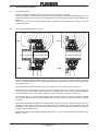
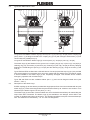
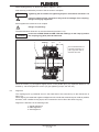
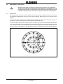
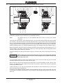
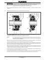
Then pull the second elastic ring (5) and retaining ring (6) onto the long side of the hub of coupling
part 2 (2) / 20 (20).
Caution!
Before fitting the second half of the elastic ring (5) care must be taken that the
two arrows marking the hole on the outer fixing point are located one above the
other (see item 10.1).
Insert two screws (7) offset at about 180° relative to one another and screw the nuts on as far as possible
by hand. The fit the other screws (7) and screw the nuts (8) on as far as possible by hand. If part 2 (2) /
20 (20) has been pulled off the shaft, it must be remounted in accordance with the instructions in
section 6.
On types EF and EFS insert into part 3 (3) / 30 (30) two screws (11) offset by 180° relative to one another.
Lay coupling part 2 (2) / 20 (20) with the attached parts in the corresponding groove in coupling ring
(9/19) or part 3 (3) / 30 (30) and insert the retaining ring (10). Screw on as far as possible by hand two
nuts (12) offset by 180° relative to one another. On types EF and EFS fit the remaining bolts (11).
Then screw on all the other nuts (12) likewise as far as possible by hand.
Tighten the nuts (8; 12) in turn (not crosswise) with the spanner. Each individual nut must not be turned
further than a quarter-turn.
If the force to be applied is sensibly greater, bring the retaining rings (6; 10) into contact with the offset
ring surfaces. Now tighten all the nuts (8; 12) in accordance with the tightening torques (see section 6,
item 6.5).
Caution!
After 24 hours the elastic rings (5) will have bedded down. At the end of this time
undo one nut (8; 12), apply Loctite 242 at one point on the threaded pin and
retighten the nut to the prescribed torque (see section 6, item 6.5).
This operation must be repeated for all nuts (8; 12).
For re-assembly, the instructions in section 6, ”Assembly”, and section 7, ”Start-up”, must be carefully
observed.
11.
Spare parts, customer-service addresses
By stocking the most important spare and wearing parts on site, you can ensure that the coupling is
ready for use at any time.
When ordering spare parts, always state the following:
– Original order no.
– Part no. (see section 11.1.)
– Description / size
– Quantity
We guarantee only the original spare parts supplied by us.
Caution!
Please note that spare parts and accessories not supplied by us have not been
tested or approved by us. The installation or use of such products may
therefore impair essential characteristics of the coupling under certain
circumstances and so pose an active or passive hazard. FLENDER will assume
no liability or guarantee for damage caused by spare parts and accessories not
supplied by FLENDER.
Please note that certain components often have special production and supply specifications and that
we supply you with spare parts which comply fully with the current state of technical development as
well as current legislation.
BA 3300 EN 01.04