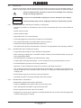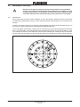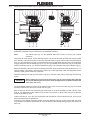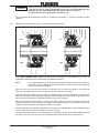
1
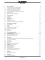
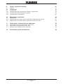
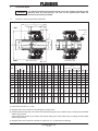
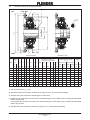
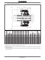
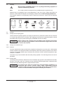
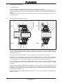
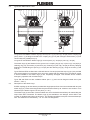
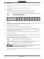
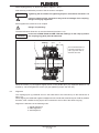
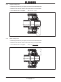
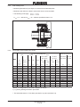
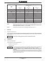
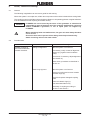
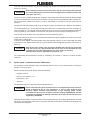
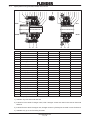
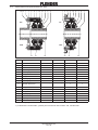
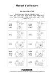
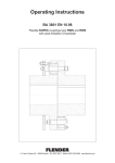
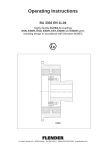
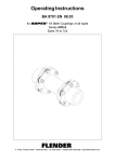
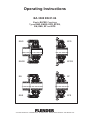
Operating Instructions
BA 3300 EN 01.04
Elastic ELPEX Couplings
Types ENG, ENGS, EFG, EFGS,
EN, ENS, EF and EFS
ENG
EFG
ENGS
EFGS
EN
EF
ENS
EFS
A. Friedr. Flender AG ⋅ 46393 Bocholt ⋅ Tel. 02871/92-0 ⋅ Telefax 02871/92-2596 ⋅ www.flender.com
Contents
1.
Technical data
1.1
1.2
1.3
1.4
1.5
1.6
1.6.1
Geometric data of types ENG and ENGS
Geometric data of types EFG and EFGS
Geometric data of types EN and ENS
Geometric data of types EF and EFS
Connecting dimensions for flanges, brake disks etc.
Performance data
Determination of the coupling size
4
5
6
7
8
9
10
2.
General notes
11
2.1
2.2
Introduction
Copyright
11
11
3.
Safety notes
11
3.1
3.2
3.3
Proper use
Obligations of the user
Warnings and symbols used in these Instructions
11
12
12
4.
Handling and storage
12
4.1
4.2
4.3
4.3.1
4.3.2
4.3.2.1
4.3.2.2
Scope of supply
Handling
Storage
Storage of the coupling parts
Storage of the elastic rings
General
Storage area
12
13
13
13
13
13
13
5.
Technical description
14
5.1
5.2
5.3
5.4
General description
Types ENG / ENGS and EFG / EFGS
Types EN / ENS and EF / EFS
Description of the elastic rings
14
14
15
15
6.
Assembly
16
6.1
Instructions for applying the finished bore and fitting the axial retaining means,
set screws and balancing
Finish bore
Axial fastening
Balancing
General information on installation
Mounting the coupling parts
Alignment
Angular misalignment
Radial misalignment
Axial misalignment
Permissible shaft misalignment values
Assignment of tightening torques
16
16
16
16
16
16
17
18
18
19
19
20
7.
Start-up
20
7.1
Procedure before start-up
20
8.
Operation
20
8.1
General operating data
20
6.1.1
6.1.2
6.1.3
6.2
6.3
6.4
6.4.1
6.4.2
6.4.3
6.4.4
6.5
4
BA 3300 EN 01.04
9.
Faults, causes and remedy
21
9.1
9.2
9.3
9.3.1
9.3.2
9.3.3
General
Possible faults
Incorrect use
Possible faults when selecting the coupling or coupling size
Possible faults when installing the coupling
Possible faults in maintenance
21
21
22
22
22
22
10.
Maintenance and repair
23
10.1
10.2
10.3
Maintenance
Replacement of the elastic rings on types ENG / ENGS and EFG / EFGS
Replacement of the elastic rings on types EN / ENS and EF / EFS
23
24
25
11.
Spare parts, customer-service addresses
26
11.1
11.2
11.3
Spare parts list of types ENG, ENGS, EFG, EFGS
Spare parts list of types EN, ENS, EF, EFS
Spare-part and customer service addresses
27
28
29
12.
Declaration by the manufacturer
34
BA 3300 EN 01.04
1.
Technical data
If a dimensioned drawing has been made out for the coupling, the data in this
drawing must be given priority. The user of the system must make the
dimensioned drawing available.
Caution!
1.1
Geometric data of types ENG and ENGS
l3
u1
u2
w1
w2
ENG
from size 840
w2
1
2
l1
l2
Size 270 to 430
ENGS
d2
l1
D2
D1
d1
da
S1
v
v
w1
Mass moment of inertia
2) 3)
Weight
2)
D1
D2
d a d 1 d 2 l 1 l 2 l 3 u 1 u 2 S 1 w 1 w 2 v Exterior parts Interior parts
from to from to
ENG ENGS ENG ENGS ENG ENGS
mm mm mm mm mm mm mm mm mm mm mm mm mm mm mm mm kgm2 kgm2 kgm2 kgm2 kg
kg
270
45
80
45
70 270 128
320
55 100
55
85 320 160 115 100 180 286 16
375
430
500
v
Size 500 to 970
Bore
1)
Size
v
94
80 155 245 14
86.0 10
79.0
42
–
0.21
0.23
0.038 0.038
32
33
97.5
88.5
48
–
0.49
0.53
0.086 0.086
55
57
65 115
65 105 375 184 143 120 205 335 18 111.8 10 103.2 62
–
1.0
1.1
0.22
0.22
87
90
75 130
75 120 430 208 165 140 235 383 22 126.0
68
–
2.0
2.2
0.39
0.39
125 130
90 150
90 150 500 240 202 160 260 432 25 139.7 12 132.3 80
–
3.9
4.2
0.88
0.88
195 200
8.9
9.1
1.80
1.80
280 290
310 320
3.90
3.90
390 410
410 430
425 445
11.50 11.50
760 800
790 830
6
8 117.0
590
100 140
224
100 170 590
230 190 310 510 28 162.7 10 157.3 95
140 180
288
–
8.2
8.4
690
110 140
224
140 180 110 200 690 288 278 220 350 580 32 175.6 10 184.4 102 70
180 210
336
16.3
16.8
16.9
17.8
18.3
18.4
840
140 180
288
140 240 840
342 280 395 685 42 231.0 10 174.0 105 90
180 220
352
49.0
50.0
54.0
55.0
970
160
200
240
280
200
320
104
240
384
106
160 280 970
390 350 505 867 70 277.0 12 230.0 137 110
280
448
110
320
512
115
4)
27
4)
1365
1410
1460
1520
4)
Table 1.1: Dimensions and weights of types ENG and ENGS
1) Hub-centre recess D1/2 +1 mm
2) Weights and mass moments of inertia apply to mean bores
3) External parts are all parts connected to the external fixing point of the elastic rings, including the associated
elastic ring portions.
Internal parts are all parts connected to the internal fixing point of the elastic rings, including the associated
elastic ring portions.
4) Weights and mass moments of inertia on request or acc. to dimensioned drawing
BA 3300 EN 01.04
1.2
Geometric data of types EFG and EFGS
u4
3
EFG
2
w1
w2
l2
l1
da
d2
D2
k
v
v
s
d3
w2
w1
30
EFGS
Size 270 to 430
Size 500 to 970
Bore
1)
Size
D2
Flanged connection 2)
SAE J620d or DIN 6288
da
d2
l1
l2
w1
w2
v
Size
d3
k
mm
mm
from to
mm mm mm mm mm mm mm mm mm
Mass moment of inertia
3) 4)
Weight
3)
s Num- u 4 Exterior parts Interior parts
ber
EFG EFGS EFG EFGS EFG EFGS
mm kgm2 kgm2
mm
kgm2
kgm2
kg
kg
270
45
70 270
94
–
155 79.0
42
–
14
466.7 438.2 13
8
12
0.47
0.49
0.038 0.038
28
29
320
55
85 320 115
–
180 88.5
48
–
16
517.5 489.0 13
8
14
0.87
0.90
0.086 0.086
45
47
375
65 105 375 143
–
205 103.2
62
–
18
571.5 542.9 17
6
16
1.54
1.61
0.022 0.022
69
73
430
75 120 430 165
–
235 117.0
68
–
21
673.5 641.4 17
12
20
3.43
3.58
0.39
0.39
106
111
500
90 150 500 202 160 260 132.3
80
–
21
673.5 641.4 17
12
20
3.96
4.26
0.88
0.88
158
163
590
100 170 590 230 190 310 157.3
95
–
24
733.5 692.2 21
12
24
7.0
7.73
1.8
1.8
208
218
690
110 200 690 278 220 350 184.4 102 70
850
890
850
17
32
24
14.7
16.2
3.9
3.9
291
311
840
140 240 840 342 280 395 174
105 90 1060 1105
1060
21
32
30
45.7
50.5
11.5
11.5
561
601
970
160 280 970 390 350 505 230
137 110 1320 1385
1320
31
24
35 130
5)
1111
5)
5)
27
Table 1.2: Dimensions and weights of types EFG and EFGS
1) Hub-centre recess D2 + 1 mm
2) Alternative flanged connection dimensions on request of acc. to dimensioned drawing
3) Weights and mass moments of inertia apply to mean bores
4) External parts are all parts connected to the external fixing point of the elastic rings, including the associated
elastic ring portions.
Internal parts are all parts connected to the internal fixing point of the elastic rings, including the associated
elastic ring portions.
5) Weights and mass moments of inertia on request or acc. to dimensioned drawing
BA 3300 EN 01.04
1.3
Geometric data of types EN and ENS
l3
u1
u2
w1
2
l2
D2
l1
D1
d1
da
1
d2
EN
S1
20
w1
ENS
Mass moment of inertia
1) 2)
Bore
Size
D1
from
D2
to
from
da
d1
d2
l1
l2
l3
u1
u2
S1
w1
Exterior parts
EN
ENS
EN
ENS
EN
ENS
mm mm
mm
kgm2
kgm2
kgm2
kgm2
kg
kg
to
mm mm mm mm mm mm mm mm mm mm mm
Weight
1)
Interior parts
140
20
45
20
32 140
72
48
50
60 114
8
43.0
4
21.0 0.0098 0.010 0.001
0.0013
4.9
5.1
180
25
55
25
42 180
88
64
60
80 144
9
53.5
4
30.5 0.030
0.033 0.0035 0.0038
9.3
9.6
220
35
65
35
55 220 104
83
70 100 176
11
68.0
6
38.0 0.083
0.085 0.013
0.013
17
17.5
270
45
80
45
65 270 128
98
80 125 211
14
86.0
6
45.0 0.230
0.24
0.033
0.035
31
33
320
55 100
55
80 320 160 120 100 140 246
16
97.5
6
48.5 0.5
0.53
0.07
0.075
51
53
375
65
115
65 100 375 184 150 120 160 288
18 111.8
8
56.2 1.1
1.2
0.18
0.19
81
84
430
75 130
75 115 430 208 172 140 180 328
22 126.0
8
62.0 2.1
2.2
0.33
0.35
120
125
500
90 150
90 140 500 240 210 160 200 368
25 139.7
8
68.3 4.1
4.4
0.75
0.8
180
190
Table 1.3: Dimensions and weights of types EN and ENS
1) Weights and mass moments of inertia apply to mean bores
2) External parts are all parts connected to the external fixing point of the elastic rings, including the associated
elastic ring portions.
Internal parts are all parts connected to the internal fixing point of the elastic rings, including the associated
elastic ring portions.
BA 3300 EN 01.04
1.4
Geometric data of types EF and EFS
u4
z
3
EF
w1
da
d2
D2
l2
d2
d3
k
d4
2
s
20
w1
30
EFS
l4
Bore
Size
D2
from
Mass moment of inertia
1) 2)
Flanged connection
da
d2
l2
to
l4
w1
d3
d4
k
s
j6
Num- u 4
ber
mm mm mm mm mm mm mm mm mm mm mm
z
mm mm
140
20
32 140
48
60
64 21.0 140 176 160
9
6
180
25
42 180
64
80
84 30.5 180 232 210
11
220
35
55 220
83 100 106 38.0 220 268 245
11
270
45
65 270
98 125 131 45.0 270 325 300
320
55
375
65
430
75
115 430 172 180 188 62.0 430 515 475
500
90
140 500 210 200 208 68.3 500 585 545
Exterior parts
Weight
1)
Interior parts
EF
EFS
EF
EFS
EF
EFS
kgm2
kgm2
kgm2
kgm2
kg
kg
6
3
0.0085 0.0088 0.0010 0.0013
3.3
3.4
6
8
3
0.030
0.032
0.0035 0.0038
6.5
6.9
8
10
4
0.075
0.078
0.013
0.015
12.5
13.0
14
8
12
4
0.14
0.18
0.033
0.035
21
22.5
80 320 120 140 146 48.5 320 392 360
18
8
14
5
0.45
0.48
0.07
0.075
34
36
100 375 150 160 168 56.2 375 448 415
18
8
16
5
0.88
0.93
0.18
0.19
53
57
22
8
20
5
1.7
1.8
0.33
0.35
78
82
22
10
20
5
3.1
3.3
0.75
0.80
115
125
Table 1.4: Dimensions and weights of types EF and EFS
1) Weights and mass moments of inertia apply to mean bores
2) External parts are all parts connected to the external fixing point of the elastic rings, including the associated
elastic ring portions.
Internal parts are all parts connected to the internal fixing point of the elastic rings, including the associated
elastic ring portions.
BA 3300 EN 01.04
Connecting dimensions for flanges, brake disks etc.
ELPEX couplings of types ENG, ENGS, EN and ENS can also be ordered without coupling part 1.
Flanges, brake disks etc can then be screwed directly on the coupling ring using existing threaded
bores. The design of the screw connection must be checked by the customer. FLENDER recommend
the use of screws of min. quality class 8.8.
t
da
Size
k
s
Coupling ring (9 / 19)
da
1.5
k
s
t
Number
h8
mm
mm
mm
140
140
120
M 8
13
6
180
180
158
M 10
16
6
220
220
196
M 10
16
8
270
270
244
M 12
18
8
320
320
288
M 16
24
8
375
375
342
M 16
24
8
430
430
390
M 20
30
8
500
500
460
M 20
30
10
590
590
542
M 24
36
10
690
690
642
M 24
36
12
840
840
780
M 30
46
12
970
950
880
M 36
53
15
Table 1.5: Connecting dimensions for flanges, brake disks etc.
BA 3300 EN 01.04
1.6
Performance data
Rated
torque
Maximum
torque
Fatigue
torque
TKN
TKmax
TKW
Nm
Nm
Nm
Speed
nmax
Axial
spring
rigidity
Radial
spring
rigidity
Ca
Cr
1x
TKN
N/mm
N/mm
Nm/rad
130
170
1400
1100
890
520
160
190
2250
1800
1400
830
250
310
3300
2750
2150
1250
450
300
350
5300
4300
3400
2000
700
380
450
7500
6200
4900
2800
950
430
510
10500
8900
7000
4000
1350
570
690
15000
12500
10000
5700
1850
660
770
22000
18500
14500
8300
2800
680
810
30000
25500
20000
11500
4000
780
910
38000
32000
25000
14500
4900
850
1010
50000
42000
32000
18000
5800
970
1130
63000
53000
41000
22500
7500
1020
1210
77000
63000
48000
26000
7000
Size
140
180
220
270
320
375
430
500
590
690
840
970
-1
100
300
40
-2
160
480
64
-1
250
750
100
-2
400
1200
160
-1
560
1680
224
-2
800
2400
320
-1
1120
3360
448
-2
1600
4800
640
-1
2240
6720
896
-2
2800
8400
1120
-1
3550
10650
1420
-2
4500
13500
1800
-1
5600
16800
2240
-2
7100
21300
2840
-1
9000
27000
3600
-2
11200
33600
4480
-1
14000
42000
5600
-2
18000
54000
7200
-1
22400
67200
8960
-2
28000
84000
11200
-1
35500
106500
14200
-2
45000
135000
18000
-1
71000
213000
28400
-2
90000
270000
36000
GG
Steel
1/min 1/min
4900
3800
3100
2500
4250
2150
3600
1800
3100
1600
2650
1350
2300
1150
2000
980
1650
820
1350
710
1180
dynamic torsional stiffness CTdyn
0.75x
TKN
0.5x
TKN
0.25x
TKN
0x
TKN
Nm/rad Nm/rad Nm/rad Nm/rad
1160
1350
97000
79000
61000
34000
10500
1230
1460
125000
97000
73000
41000
14000
1410
1630
155000
120000
90000
50000
16500
1510
1790
190000
145000
110000
62000
19500
1710
1990
240000
185000 140000
79000
29000
1820
2150
295000
230000 175000
98000
33500
2060
2390
365000
285000 215000 120000
41000
2270
2680
540000
420000 315000 175000
57000
2570
2990
685000
535000 400000 220000
75000
2670
3160
910000
680000 520000 290000 100000
3020
3510
1100000
880000 640000 350000 130000
damping coefficient = 1.1
Resonance factor VR = 5.7
The performance data are valid for:
S max. 25 starts per hour
S daily operating cycle of up to 24 h
S operation within the specified alignment
S Operation in the temperature range -30 °C to +80 °C in the immediate vicinity of the coupling
Caution!
For sustained faultfree operation the coupling must be designed with an safety
factor SS and temperature factor Sϑ appropriate to the application. In the event
of a change in operating conditions (e.g. output, speed, starting frequency,
changes to the prime mover and driven machine) the design must always be
checked (see item 1.6.1).
BA 3300 EN 01.04
1.6.1
Determination of the coupling size
It is to be selected from the coupling series the coupling to which applies:
TKN w TN
SS
Sϑ
TKN
TN
SS
SS
Sϑ
= Rated coupling torque
= Rated system torque rated drive torque acting on the coupling
= 1.4 for small coefficients of cyclic variation
(eg. diesel-motor generator drive)
= 1.6 for large coefficients of cyclic variation
(eg. diesel-motor compressor drive)
= Temperature factor
The temperature in the immediate vicinity of the coupling must be applied.
TU
from -40 °C to +40 °C
from +40 °C to +60 °C
from +60 °C to +70 °C
from +70 °C to +80 °C
Sϑ
1
1.25
1.4
1.6
Table 1.6.1: Temperature factor Sϑ
During starting or operation torque impulses up to 25 times per hour are permissible. The following
applies:
TKmax w Tmax
Sϑ
TKmax = Maximum coupling torque
Tmax = Maximum system torque peak drive torque acting on the coupling
Sϑ
= Temperature factor
The following must apply to the alternating torques occurring during operation:
TKW w TW
Sf
Sϑ
TKW
TW
Sϑ
= Fatigue torque load on the coupling
= Alternating torque load on the coupling
= Temperature factor
f
Ǹ10Hz
Sf
+
Sf
+ 1.0
f Err
Err
for f Err > 10 Hz
for f Err v 10 Hz
= excitation frequency of the alternating torque load in Hz
Caution!
When selecting the coupling, the permissible maximum speed and the
permissible maximum bore must also be taken into consideration.
Caution!
The shaft displacement values specified in section 6, item 6.4.4, must not be
exceeded.
BA 3300 EN 01.04
2.
General notes
2.1
Introduction
These Operating Instructions (BA) are an integral part of the coupling delivery and must be kept in its
vicinity for reference at all times.
All persons involved in the installation, operation, maintenance and repair of
the coupling must have read and understood these Operating Instructions and
must comply with them at all times. We accept no responsibility for damage or
disruption caused by disregard of these Instructions.
Caution!
The ”Coupling” described in these operating instructions has been developed for stationary use in
general engineering applications. The coupling serves to transmit power and torque between two shafts
or flanges connected by this coupling.
The coupling is designed only for the application described in section 1, ”Technical data”. Other
operating conditions must be contractually agreed.
The coupling described in these Instructions reflects the state of technical development at the time
these Instructions went to print.
In the interest of technical progress we reserve the right to make changes to the individual assemblies
and accessories which we regard as necessary to preserve their essential characteristics and improve
their efficiency and safety.
2.2
Copyright
The copyright to these Operating Instructions (BA) is held by FLENDER AG.
These Operating Instructions (BA) must not be wholly or partly reproduced for competitive purposes,
used in any unauthorised way or made available to third parties without our agreement.
Technical enquiries should be addressed to the following works
FLENDER AG
D 46393 Bocholt
Telephone: 02871/92-2868
Telefax:
02871/92-2579
or to one of our customer-service addresses. A list of our customer-service addresses is given in
section 11, ”Spare parts, customer-service addresses”.
3.
Safety notes
3.1
Proper use
S The coupling has been manufactured in accordance with the state of the art and is delivered in a
condition for safe and reliable use. Any changes on the part of the user which may affect safety and
reliability are prohibited. This applies equally to safety features designed to prevent accidental
contact.
S The coupling must be used and operated strictly in accordance with the conditions laid down in the
contract governing performance and supply.
BA 3300 EN 01.04
3.2
Obligations of the user
S The operator must ensure that all persons involved in installation, operation, maintenance and repair
have read and understood these Operating Instructions (BA) and comply with them at all times in
order to:
– avoid injury or damage,
– ensure the safety and reliability of the coupling,
and
– avoid disruptions and environmental damage through incorrect use.
S During transport, assembly, installation, dismantling, operation and maintenance of the unit, the
relevant safety and environmental regulations must be complied with at all times.
S The coupling must be operated, maintained or repaired only by authorised, duly trained and qualified
personnel.
S All work must be carried out with great care and with due regard to safety.
S All work on the gear unit must be carried out only when it is at a standstill.
The drive unit must be secured against being switched on accidentally (e.g. by locking the key switch
or removing the fuses from the power supply). A notice should be attached to the ON switch stating
clearly that work is in progress.
S The coupling must be fitted with suitable safeguards to prevent accidental contact. The operation of
the coupling must not be impaired by the safeguard.
S The drive unit must be shut down as soon as changes to the coupling are detected during operation.
S If the coupling is intended for installation in plant or equipment, the manufacturer of such plant or
equipment must ensure that the contents of the present Operating Instructions are incorporated in
his own instructions.
S All spare parts must be obtained from FLENDER.
3.3
Warnings and symbols used in these Instructions
This symbol indicates safety measures which must be observed to avoid personal
injury.
Caution!
Note:
This symbol indicates safety measures which must be observed to avoid damaging
the coupling.
This symbol indicates general operating instructions which are of particular
importance.
4.
Handling and storage
4.1
Scope of supply
The products supplied are listed in the despatch papers. Check immediately on receipt to ensure that
all the products listed have actually been delivered. Parts damaged during transport or missing parts
must be reported in writing immediately.
ELPEX couplings are supplied with finished bore and in pre-assembled condition.
BA 3300 EN 01.04
4.2
Handling
When handling FLENDER products, use only lifting and handling equipment of
sufficient load-bearing capacity!
Note:
The coupling must be transported using suitable transport equipment only.
Different forms of packaging may be used depending on the size of the coupling and method of
transport. Unless otherwise agreed, the packaging complies with the HPE Packaging Guidelines.
The symbols marked on the packaging must be observed at all times. These have the following
meanings:
bild-transport
This way
up
Fragile
4.3
Storage
4.3.1
Storage of the coupling parts
Keep
dry
Keep
cool
Centre of
gravity
Use no
hand hook
Attach
here
Unless otherwise expressly agreed, the coupling is delivered in a preserved condition and can be stored
in a covered, dry place for up to 3 months. If the coupling is to be stored for a protracted period, it should
be treated with a long-term preservative agent (FLENDER must be consulted).
Caution!
4.3.2
Before cleaning the coupling parts and applying the long-term preservative
agent, the elastic ring (5) must be covered. The eleastic ring (5) must not come
in contact with solvents.
Storage of the elastic rings
4.3.2.1 General
Correctly stored elastic rings (5) retain their properties unchanged for up to five years. Unfavourable
storage conditions and improper treatment will negatively affect the physical properties of the elastic
rings (5). Such negative effects may be caused by e.g. the action of ozone, extreme temperatures, light,
moisture, or solvents.
The elastic rings must be laid flat with the bead pointing upwards. The matching halves must not be
separated.
4.3.2.2 Storage area
The storage area must be dry and free from dust. The elastic rings (5) must not be stored with chemicals,
solvents, motor fuels, acids, etc. Furthermore, they should be protected against light, in particular direct
sunlight and bright artificial light with a high ultraviolet content.
Caution!
The storage areas must not contain any ozone-generating equipment, e.g.
fluorescent light sources, mercury vapour lamps, high-voltage electrical
equipment. Damp storage areas are unsuitable. Ensure that no condensation
occurs. The most favourable atmospheric humidity is below 65 %.
BA 3300 EN 01.04
5.
Technical description
5.1
General description
ELPEX couplings are highly elastic, torsional-vibration-insulating couplings.
They are suitable for connecting machines and can compensate for important shaft misalignment. The
restorative forces set up are low and can be determined with the specified axial and radial rigidities (see
section 1).
Because of the friction connection of the elastic rings (5) in the metal parts the coupling is free of
torsional backlash.
5.2
Types ENG / ENGS and EFG / EFGS
36 13,14 1 7 9 11 5 17 10 12 6 8 16 2
36 7 3 11 5 17 10 12 6 8 16 2
ENG
EFG
ENGS
EFGS
19
21
22
30
21
22
On types ENG and ENGS the elastic rings (5) connect part 1 (1) to part 2 (2) via the coupling ring (9/19).
Part 1 (1) is flange-mounted to the coupling ring (9/19) with hexagon head screws (14) and centred with
two parallel pins (13).
On types EFG and EFGS the elastic rings (5) connect part 3 (3) / part 30 (30) to part 2 (2).
The elastic rings (5) are fastened in the groove in the coupling ring (9/19) / of part 3 (3) / 30 (30) by a
retaining ring (10), set screws (11) and nuts (12). Fastening on part 2 (2) is done by clamping between
the raised flange of part 2 (2) and the retaining ring (6), using set screws (7) and nuts (8).
The retaining ring (17) / stop ring (22) between the two elastic rings (5) is also in two parts, enabling
the fitting and demounting of the split elastic rings (5) to be carried out without moving the coupled
machines.
Types ENGS and EFGS are fitted with a fail-safe device. The stop rings (21; 22) are provided with cams
engaging in one another which come into contact with one another only if a maximum torque is well
exceeded or if the elastic rings (5) are irreparably damaged. This fail-safe device enables emergency
operation with a limited torque.
Types ENG and ENGS are also available without part 1 (1) and can be flange-mounted direct (see
section 1, item 1).
BA 3300 EN 01.04
5.3
Types EN / ENS and EF / EFS
13,14
1
7
9
11
5 10 12
6
8
2
7
EN
EF
ENS
EFS
19
21
20
3
30
11
5 10 12
21
6
8
2
20
On types EN and ENS the elastic rings (5) connect part 1 (1) to part 2 (2) / 20 (20) via the coupling ring
(9/19). Part 1 (1) is flange-mounted to the coupling ring (9 /19) with hexagon head screws (14) and
centred with two parallel pins (13).
On types EF and EFS the elastic rings (5) connect part 3 (3) / 30 (30) to part 2 (2) / 20 (20).
The elastic rings (5) are fastened in the groove in the coupling ring (9/19) / of part 3 (3) / 30 (30) by a
retaining ring (10), set screws (11) and nuts (12). Fastening on part 2 (2) / 20 (20) is done by clamping
between the raised flange of part 2 (2) / 20 (20) and the retaining ring (6), using set screws (7) and
nuts (8).
Types ENS and EFS are fitted with a fail-safe device. Part 20 (20) and the stop ring (21) are provided
with cams engaging in one another which come into contact with one another only if a maximum torque
is well exceeded or the elastic rings (5) are irreparably damaged. This fail-safe device enables
emergency operation with a limited torque.
Types EN and ENS are also available without part 1 (1) and can be flange-mounted direct (see
section 1, item 1).
5.4
Description of the elastic rings
ELPEX couplings up to size 220 are provided with single-part and from size 270 to size 690 with two-part
elastic rings (5). These are arranged with the part surfaces offset by 90° relative to one another. From
size 840 up the elastic rings are in four parts ( 4 x 90°).
The elastic rings (5) are made of natural rubber into which the double-thread inlays for transmitting the
torque have been vulcanised. The elastic rings (5) are available in two designs, which differ in the
number of double-thread inlays vulcanised in. This enables two different torques to be transmitted per
size. This distinction is indicated by -1 or -2 in the size designation.
BA 3300 EN 01.04
6.
Assembly
6.1
Instructions for applying the finished bore and fitting the axial retaining means, set screws and balancing
6.1.1
Finish bore
ELPEX couplings are supplied with finished bore and with fitted keyway.
6.1.2
Axial fastening
Axial securing of the coupling halves is effected by means of set screws or end plates.
Set screws with cup points to DIN 916 must be used when replacing the set screws.
The length of the set screw must be selected so that it fills the threaded hole,
but does not project from the hub.
(Lmin. = set screw diameter x 1.2)
Set screw size
M5
M6
M8
M 10
M 12
M 16
M 20
M 24
M 30
Tightening torque TA
3
4
8
15
25
70
130
230
470
Table 6.1.2: Tightening torques of the set screws
6.1.3
Balancing
ELPEX coupling are executed to customer specifications or in accordance with half parallel keyway
agreement (DIN ISO 8821) with balancing quality G16 (DIN ISO 1940).
6.2
General information on installation
During assembly, the ”Safety Instructions” in Section 3 must be observed.
Assembly and installation work must be done with great care by trained and qualified personnel.
As early as during the planning phase it must be ensured that sufficient space is available for installation
and subsequent care and maintenance work.
Adequate lifting equipment must be available before beginning the installation and assembly work.
6.3
Mounting the coupling parts
ELPEX coupling are assembled ready for installation. For fitting the coupling parts with types
ENG / ENGS and EN / ENS screws (14) must be undone.
Prior to starting the fitting, the wooden parts for supporting the elastic rings (5) must be removed and
the shaft ends as well as the coupling parts thoroughly cleaned.
Note manufacturer’s instructions for handling solvent.
If necessary, heating part 1 (1) (to max. + 150 °C) will facilitate fitting. Part 2 (2) / 20 (20) may only be
heated up to a max. temperature of + 80 °C due to the elastic ring (5) screwed on it.
Take precautions to avoid burns from hot components!
Caution!
The coupling parts must be fitted with the aid of suitable equipment to avoid
damaging the shaft bearings through axial joining forces.
Always use suitable lifting equipment.
The coupling parts must be fitted completely on the shaft, while the shaft ends must not project from
the inner sides of the hub.
BA 3300 EN 01.04
Allow coupling parts (1; 2; 20) to cool down to approx. + 30 °C.
Axial securing is effected by means of the set screw or end plate.
Caution!
Tightening the set screws to a tightening torque in accordance with item 6.1.2.
Failure to observe these instructions may result in breakage of the coupling.
Danger from flying fragments!
Move together the machines to be coupled.
Danger of squeezing!
The axial reference dimension w must be observed (see item 6.4.4).
Caution!
In the case of ENG / ENGS and EN / ENS the markings on the coupl (1) and on
the coupling ring (9/19) must be observed.
1
Identification
marking
9/19
w
* The actual dimension “w”
has been punched in on
part 2 (2) in the case of
sizes 840 and 970.
*
w
Place the screws (14) and tighten slightly. Knock in the parallel pins (13) displaced relative to one
another by 180° and tighten the screws (14) (for tightening torque, see item 6.5).
6.4
Alignment
The couplings pick up positional errors in the shaft ends to be connected up to the data shown in
item 6.4.4.
When aligning, the radial and angular misalignment of the shaft ends must be kept as small as possible,
because, other conditions being equal, this increases the service life of the elastic rings (5).
Alignment is best done in the following order:
1. angular alignment
2. radial alignment
3. axial alignment
BA 3300 EN 01.04
6.4.1
Angular misalignment
S Measuring dimension b (see figure) on several circumferential points.
S Maximum and minimum values b max and b min are to be recorded.
S In accordance with 6.4.4 applies:
W w b max – b min
b
Radial misalignment
S Measuring dimension a (see figure) on several circumferential points.
S Maximum and minimum values a max and a min are to be recorded.
S In accordance with 6.4.4 applies:
K Rperm w
a max * a min
2
a
6.4.2
BA 3300 EN 01.04
6.4.3
Axial misalignment
S Measuring dimension b (see figure) on several circumferential points.
S Maximum and minimum values b max and b min are to be recorded.
S The following must apply:
w min < b min
w max > b max
w min = w – Ka and w max = w + Ka are specified on item 6.4.4.
w
b
6.4.4
Permissible shaft misalignment values
max. perm. shaft misalignment
angular
axial
radial
ENG, ENGS,
EFG, EFGS
Size
Kr
Kr max.
continuous
mm
short-time
Kw
W
Ka
w min
w max
Reference dimension w
EN, ENS,
EF, EFS
w min
ENG, ENGS, EN, ENS,
EFG, EFGS EF, EFS
w max
w – Ka w + Ka w – Ka w + Ka
°
mm
mm
mm
mm
mm
mm
mm
mm
140
1.0
2.0
0.2
0.5
1.0
–
–
20.0
22.0
–
21.0
180
1.4
3.0
0.2
0.6
1.4
–
–
29.1
31.9
–
30.5
220
1.8
3.5
0.2
0.7
1.8
–
–
36.2
39.8
–
38.0
270
2.2
4.5
0.2
0.9
2.2
76.8
81.2
42.8
47.2
79.0
45.0
320
2.6
5.0
0.2
1.1
2.6
85.9
91.1
45.9
51.1
88.5
48.5
375
3.0
6.0
0.2
1.3
3.0
100.2
106.2
53.2
59.2
103.2
56.2
430
3.4
7.0
0.2
1.5
3.4
113.6
120.4
58.6
65.4
117.0
62.0
500
3.8
7.5
0.2
1.7
3.8
128.5
136.1
64.5
72.1
132.3
68.3
590
4.2
8.5
0.2
2.0
4.2
153.1
161.5
–
–
157.3
–
690
4.6
9
0.2
2.4
4.6
179.8
189.0
–
–
184.4
–
840
5.0
10
0.2
2.9
5.0
w–5
w+5
–
–
*
–
970
5.5
11
0.2
3.4
5.5
w – 5.5
w + 5.5
–
–
*
–
mm
Table 6.4.4: Assignment of the shaft misalignment values
1) e.g. during starting and switch processes
* The actual dimension “w” has been punched in on part 2 (see item 6.3).
BA 3300 EN 01.04
6.5
Assignment of tightening torques
Tightening torques
TA
Size
Part no. 8
Part no. 12
Part no. 13
Nm
Nm
Nm
140
4.5
4.5
25
180
7.5
7.5
49
220
18
18
49
270
35
18
86
320
35
35
210
375
55
55
210
430
55
55
410
500
130
55
410
590
130
130
710
690
250
130
710
840
250
250
1450
970
435
435
2530
Table 6.5: Assignment of tightening torques
Note:
Tightening torques apply to screws with untreated surfaces which are not or only
lightly oiled (coefficient of friction µ = 0.14). The use of lubricant paint or the like, which
affects the coefficient of friction µ, is not permitted.
Note:
The tightening torques of the set screws are specified in item 6.1.2.
7.
Start-up
7.1
Procedure before start-up
Before starting up, check the tightness of the set screws, check and, if necessary, adjust the alignment
and the distance dimension w, and check the specified tightening torques of all the screw connections
(see section 6).
Caution!
Then fit the coupling guard to prevent unintentional contact.
8.
Operation
8.1
General operating data
During operation of the coupling watch for:
– changes in running noise
– sudden shocks
Caution!
If any irregularities are noticed during operation, switch the drive assembly off
at once. Determine the cause of the fault, using the table in section 9.
This table contains a list of possible faults, their causes and suggested
remedies.
If the cause cannot be identified or the unit repaired with the facilities available,
you are advised to contact one of our customer-service offices for specialist
assistance (see section 11.).
BA 3300 EN 01.04
9.
Faults, causes and remedy
9.1
General
The following irregularities can serve as a guide for fault tracing.
Where the system is a complex one, all the other component units must be included when tracing faults.
The coupling must run with little noise and without vibration in all operating phases. Irregular behaviour
must be treated as a fault requiring immediate remedy.
Caution!
FLENDER will not be bound by the terms of the guarantee or otherwise be
responsible in cases of improper use of the coupling, modifications carried out
without FLENDER’s agreement, or use of spare parts not supplied by
FLENDER.
When remedying faults and malfunctions, the gear unit must always be taken
out of service.
Secure the drive unit to prevent it from being started up unintentionally.
Attach a warning notice to the start switch!
9.2
Possible faults
Malfunctions
Sudden changes in
the noise level and/or
sudden vibrations.
Causes
Change of alignment.
Remedy
take the system out of service.
if necessary, rectify causes of alignment
change (e.g. tighten loose foundation
bolts).
Check and, if necessary, adjust alignment
(see section 6).
Wear check, procedure as described in
section 10.
Elastic rings (5) worn.
take the system out of service.
Demount coupling and remove remains
of elastic rings (5).
Check and replace damaged coupling
parts
Place new elastic rings (5);
use associated halves only.
Assembly of coupling according to
section 6. and section 7.
Table 9.2: Possible faults
BA 3300 EN 01.04
9.3
Incorrect use
Experience has shown that the following faults can result in incorrect use of the ELPEX coupling. In
addition to observing the other instructions in this BA, care must therefore be taken to avoid these faults.
Failure to observe these instructions may result in breakage of the coupling.
Danger from flying fragments!
9.3.1
Caution!
Incorrect use of the ELPEX coupling can result in damage to the coupling.
Caution!
Coupling damage may result in stoppage of the drive and the entire system.
Possible faults when selecting the coupling or coupling size
S Important information for describing the drive and the environment will not be communicated to
others.
S System torque too high.
S System speed too high.
S Application factor not correctly selected.
S Chemically aggressive environment not taken into consideration.
S The ambient temperature is not permissible. See also section 1.
S Finished bore with unpermissible diameter (Section 1).
S The transmission capacity of the shaft-hub connection is not appropriate to the operating conditions.
9.3.2
Possible faults when installing the coupling
S Components with transport or other damage are being fitted.
S When mounting coupling parts in a heated condition, already mounted ELPEX elastic rings (5) are
being inadmisisbly heated.
S The shaft diameter is outside the specified tolerance range.
S Coupling parts are being interchanged, i.e. their assignment to the specified shaft is incorrect.
S Prescribed tightening torques are not being adhered to.
S Alignment or shaft misalignment values do not match the operating instructions.
S The coupled machines are not correctly fastened to the foundation, so a shifting of the machines e.g.
through loosening of the foundation screw connection is causing excessive displacement of the
coupling parts.
S ELPEX elastic rings (5) are not being correctly positioned.
S Operating instructions are being changed without authorisation.
9.3.3
Possible faults in maintenance
S Maintenance intervals are not being adhered to.
S Original FLENDER ELPEX elastic rings (5) are not being used.
S Old or damaged ELPEX elastic rings (5) are being used.
S Elastic ring halves are used, which do not match.
S Leakage in the vicinity of the coupling is not being identified and as a result chemically aggressive
media are damaging the coupling.
BA 3300 EN 01.04
10.
Maintenance and repair
All work on the gear unit must be carried out only when it is at a standstill.
The drive unit must be secured against being switched on accidentally (e.g. by
locking the key switch or removing the fuses from the power supply). A notice
should be attached to the ON switch stating clearly that work is in progress.
10.1
Maintenance
During maintenance of the machine installation in which the ELPEX coupling has been incorporated,
the externally situated elastic ring (5) is to be visually inspected. Dismounting is nor necessary to this
purpose.
Cracks in the rubber surface do not affect the functionability and service life of the elastic ring (5), as
the torque is mostly transmitted by the embedded double-thread inlays.
The functionability of the ELPEX coupling can be checked only by the torsional displacement between
the in- and output side. Three triangles have been applied to the elastic ring (5) (see illustration). If the
inner triangle is inside the zone enclosed by the two outer triangle,s the coupling is fully functionable.
As soon as the inner triangle is to the right or left of this zone, the elastic rings (5) must be replaced.
BA 3300 EN 01.04
10.2
Replacement of the elastic rings on types ENG / ENGS and EFG / EFGS
36 13;14 1 7 9 11 5 17 10 12 6 8 16 2
4
36 7 3 11 5 17 10 12 6 8 16 2
ENG
EFG
ENGS
EFGS
19
21
22
30
21
22
Only original ELPEX elastic rings must be used for replacement for the elastic ring (5) in order to
guarantee troublefree torque transmission and faultfree operation.
Note:
The elastic rings (5) can be replaced without the need of moving the coupled
machines.
After removal of the nuts (8; 12) the retaining rings (6; 10) can be removed up to the hub end (if possible
even further). Pull back and remove the now exposed elastic ring (5). Remove the two-part retaining
ring (17) / two-part stop ring (22). On sizes 840 and 970 of types ENG and EFG remove the adaptor
ring (4) and place with the retaining rings (6; 10). On type ENGS pull out the stop ring (21) and place
with the retaining rings (6; 10). Remove parallel key (36). Pull back anbd remove the elastic ring (5).
Before reassembly clean the area for mounting the elastic rings (5) and check the parallel pins (7; 11)
for firm seating. If necessary, resecure with Loctite (e.g. Loctite Type 242). Clean and degrease screws
carefully. Allow grease solvent to evaporate.
Assembly takes place with the new elastic rings (5) in reverse order and by observing the following
points.
Caution!
Before fitting the second half of the elastic ring (5) care must be taken that the
two arrows marking the hole on the outer fixing point are located one above the
other (see item 10.1).
On types ENGS and EFGS care must be taken that the cams on the outer stop ring (21) are centred
precisely between the cams on the inner stop ring (22).
Both on the inner and on the outer fixing point first screw on as far as possible by hand only two of the
nuts (8; 12), displaced at 180° relative to each other. Then screw on all the other nuts (8; 12) likewise
as far as possible by hand.
Tighten the nuts (8; 12) in turn (not crosswise) with the spanner. Each individual nut (8; 12) must not
be turned further than a quarter-turn.
If the force to be applied is sensibly greater, bring the retaining rings (6; 10) into contact with the offset
ring surfaces. Now tighten all the nuts (8; 12) in accordance with the tightening torques (see section 6,
item 6.5).
BA 3300 EN 01.04
After 24 hours the elastic rings (5) will have bedded down. At the end of this time
undo one nut (8; 12), apply Loctite 242 at one point on the threaded pin and
retighten the nut to the prescribed torque (see section 6, item 6.5).
This operation must be repeated for all nuts (8; 12).
Caution!
For re-assembly, the instructions in section 6, ”Assembly”, and section 7, ”Start-up”, must be carefully
observed.
10.3
Replacement of the elastic rings on types EN / ENS and EF / EFS
13,14
1
7
9
11
5 10 12
6
8
2
7
EN
EF
ENS
EFS
19
21
20
3
30
11
5 10 12
21
6
8
2
20
Only original ELPEX elastic rings must be used for replacement for the elastic ring in order to
guarantee troublefree torque transmission and faultfree operation.
Note:
The coupled machines must be shifted to enable the elastic rings (5) to be replaced.
Up to size 220 part 2 (2)/20 (20) must be pulled off the shaft to enable the single-part
elastic rings (5) to be replaced.
After the nuts (12) have been removed, the retaining ring (10) must be located on the shaft and
part 2 (2) / 20 (20) pulled out of the coupling ring (9/19) or part 3 (3) / 30 (30).
After the nuts (8) and screws (7) are undone the retaining rings (6) can be removed or located on the
shaft. From size 270 up the split elastic rings (5) can be removed. Up to size 220 part 2 (2) / 20 (20) must
be removed from the shaft to enable the elastic rings (5) to be replaced.
Before reassembly clean the area for mounting the elastic rings (5). Check the set screws (11) in the
coupling ring (9/ 19) for firm seating. If necessary, resecure with Loctite (e.g. Loctite 242). Clean and
degrease screws carefully. Allow grease solvent to evaporate.
Assembly begins by scrrewing together the inner fixing point. Pull flexible ring (5) and a retaining ring (6)
onto the short side of the hub of coupling part 2 (2) / 20 (20).
On types ENS and EFS lay the outer stop ring (21) on the elastic ring (5). Care must be taken here that
the cams of the outer stop ring (21) are centred precisely between the cams of the hub (20).
BA 3300 EN 01.04
Then pull the second elastic ring (5) and retaining ring (6) onto the long side of the hub of coupling
part 2 (2) / 20 (20).
Caution!
Before fitting the second half of the elastic ring (5) care must be taken that the
two arrows marking the hole on the outer fixing point are located one above the
other (see item 10.1).
Insert two screws (7) offset at about 180° relative to one another and screw the nuts on as far as possible
by hand. The fit the other screws (7) and screw the nuts (8) on as far as possible by hand. If part 2 (2) /
20 (20) has been pulled off the shaft, it must be remounted in accordance with the instructions in
section 6.
On types EF and EFS insert into part 3 (3) / 30 (30) two screws (11) offset by 180° relative to one another.
Lay coupling part 2 (2) / 20 (20) with the attached parts in the corresponding groove in coupling ring
(9/19) or part 3 (3) / 30 (30) and insert the retaining ring (10). Screw on as far as possible by hand two
nuts (12) offset by 180° relative to one another. On types EF and EFS fit the remaining bolts (11).
Then screw on all the other nuts (12) likewise as far as possible by hand.
Tighten the nuts (8; 12) in turn (not crosswise) with the spanner. Each individual nut must not be turned
further than a quarter-turn.
If the force to be applied is sensibly greater, bring the retaining rings (6; 10) into contact with the offset
ring surfaces. Now tighten all the nuts (8; 12) in accordance with the tightening torques (see section 6,
item 6.5).
Caution!
After 24 hours the elastic rings (5) will have bedded down. At the end of this time
undo one nut (8; 12), apply Loctite 242 at one point on the threaded pin and
retighten the nut to the prescribed torque (see section 6, item 6.5).
This operation must be repeated for all nuts (8; 12).
For re-assembly, the instructions in section 6, ”Assembly”, and section 7, ”Start-up”, must be carefully
observed.
11.
Spare parts, customer-service addresses
By stocking the most important spare and wearing parts on site, you can ensure that the coupling is
ready for use at any time.
When ordering spare parts, always state the following:
– Original order no.
– Part no. (see section 11.1.)
– Description / size
– Quantity
We guarantee only the original spare parts supplied by us.
Caution!
Please note that spare parts and accessories not supplied by us have not been
tested or approved by us. The installation or use of such products may
therefore impair essential characteristics of the coupling under certain
circumstances and so pose an active or passive hazard. FLENDER will assume
no liability or guarantee for damage caused by spare parts and accessories not
supplied by FLENDER.
Please note that certain components often have special production and supply specifications and that
we supply you with spare parts which comply fully with the current state of technical development as
well as current legislation.
BA 3300 EN 01.04
11.1
Spare parts list of types ENG, ENGS, EFG, EFGS
36 13,14 1 7 9 11 5 17 10 12 6 8 16 2
4
36 7 3 11 5 17 10 12 6 8 16 2
ENG
EFG
ENGS
EFGS
19
Part no.
21
22
30
Description
ENG
ENGS
1
Part 1
x
x
2
Part 2
x
x
3
Part 3
4
Adaptor ring
5
Elastic ring
6
Retaining ring
7
Screw stud
2)
8
Hexagon nut
2)
9
Coupling ring
10
Retaining ring
11
Screw stud
3)
12
Hexagon nut
3)
13
14
21
22
EFG
EFGS
x
x
x
1)
x
x
x
x
x
x
x
x
x
x
x
x
x
x
x
x
x
x
x
x
x
x
x
x
x
x
x
x
x
x
Parallel pin
x
x
Hexagon head screw
x
x
16
Parallel key
x
x
x
x
17
Split retaining ring
x
19
Coupling ring
x
21
Stop ring
x
x
22
Split stop ring
x
x
30
Part 30
36
Parallel key
x
x
x
4)
x
x
x
x
Table 11.1: Spare parts list
1) availabe only with sizes 840 and 970
2) Instead of screw studs / hexagon nuts, bolts / hexagon screws are used in the case of sizes 840
and 970.
3) Instead of screw studs / hexagon nuts, hexagon screws / cylinder pins are used in case of size 970.
4) available only up to and including size 690
BA 3300 EN 01.04
11.2
Spare parts list of types EN, ENS, EF, EFS
13,14
1
7
9
11
5 10 12
6
8
2
7
EN
EF
ENS
EFS
19
Part no.
21
Description
20
3
30
EN
ENS
x
11
5 10 12
21
6
8
2
20
EF
EFS
1
Part 1
x
2
Part 2
x
3
Part 3
5
Elastic ring
x
x
x
x
6
Retaining ring
x
x
x
x
7
Hexagon head screw
x
x
x
x
8
Hexagon nut
x
x
x
x
9
Coupling ring
x
10
Retaining ring
x
x
x
x
11
Screw stud
Hexagon head screw
x
x
x
12
Hexagon nut
x
x
x
x
13
Parallel pin
x
x
14
Hexagon head screw
x
x
19
Coupling ring
x
20
Part 20
x
x
21
Stop ring
x
x
30
Part 30
x
x
1)
x
1)
x
Table 11.2: Spare parts list
1) Instead of the screw studs, cylinder pins are used in case of sizes 140, 180 and 220.
BA 3300 EN 01.04
11.3
Spare-part and customer service addresses
When ordering spare parts or requesting the services of our specialist engineers, please apply first to
FLENDER AG.
FLENDER Germany
A. FRIEDR. FLENDER AG
46393 Bocholt - Tel.: (0 28 71) 92-0 - Fax: (0 28 71) 92 25 96
E-mail: [email protected] S www.flender.com
Shipping address: Alfred - Flender - Strasse 77 - 46395 Bocholt
A. FRIEDR. FLENDER AG - Kupplungswerk Mussum
Industriepark Bocholt - Schlavenhorst 100 - 46395 Bocholt - Tel.: (0 28 71) 92 28 68 - Fax: (0 28 71) 92 25 79
E-mail: [email protected] S www.flender.com
A. FRIEDR. FLENDER AG - Werk Friedrichsfeld
Am Industriepark 2 - 46562 Voerde - Tel.: (0 28 71) 92-0 - Fax: (0 28 71) 92 25 96
E-mail: [email protected] S www.flender.com
Winergy AG
Am Industriepark 2 - 46562 Voerde - Tel.: (0 28 71) 924 - Fax: (0 28 71) 92 24 87
E-mail: [email protected] S www.winergy-ag.com
A. FRIEDR. FLENDER AG - Getriebewerk Penig
Thierbacher Strasse 24 - 09322 Penig - Tel.: (03 73 81) 60 - Fax: (03 73 81) 8 02 86
E-mail: [email protected] S www.flender.com
FLENDER - TÜBINGEN GMBH
72007 Tübingen - Tel.: (0 70 71) 7 07-0 - Fax: (0 70 71) 70 74 00
E-mail: [email protected] S www.flender.com
Shipping address: Bahnhofstrasse 40 - 72072 Tübingen
LOHER GMBH
94095 Ruhstorf - Tel.: (0 85 31) 3 90 - Fax: (0 85 31) 3 94 37
E-mail: [email protected] S www.loher.de
Shipping address: Hans-Loher-Strasse 32 - 94099 Ruhstorf
FLENDER SERVICE GMBH
44607 Herne - Tel.: (0 23 23) 940-0 - Fax: (0 23 23) 940 333
E-mail: [email protected] S www.flender-service.com
24h Service Hotline +49 (0) 17 22 81 01 00
Shipping address: Südstrasse 111 - 44625 Herne
A. FRIEDR. FLENDER AG - FLENDER GUSS
Obere Hauptstrasse 228-230 - 09228 Chemnitz / Wittgensdorf - Tel.: (0 37 22) 64-0 - Fax: (0 37 22) 64 21 89
E-mail: [email protected] S www.flender-guss.de
BA 3300 EN 01.04
Germany
A. FRIEDR. FLENDER AG
46393 BOCHOLT - TEL.: (0 28 71) 92 - 0 - FAX: (0 28 71) 92 25 96
SHIPPING ADDRESS: ALFRED - FLENDER - STRASSE 77 - 46395 BOCHOLT
––––––––––––––––––––––––––––––––––––––––––––––––––––––––––––––
E-mail: [email protected]
S
www.flender.com
––––––––––––––––––––––––––––––––––––––––––––––––––––––––––––––
VERTRIEBSZENTRUM BOCHOLT
46393 Bocholt
Alfred-Flender-Strasse 77, 46395 Bocholt
Tel.: (0 28 71) 92 - 0
Fax: (0 28 71) 92 - 14 35
E-mail: [email protected]
___________________________________________________________________________________________________________
VERTRIEBSZENTRUM STUTTGART
70472 Stuttgart
Friolzheimer Strasse 3, 70499 Stuttgart
Tel.: (07 11) 7 80 54 - 51
Fax: (07 11) 7 80 54 - 50
E-mail: [email protected]
___________________________________________________________________________________________________________
VERTRIEBSZENTRUM MÜNCHEN
85750 Karlsfeld
Liebigstrasse 14, 85757 Karlsfeld
Tel.: (0 81 31) 90 03 - 0
Fax: (0 81 31) 90 03 - 33
E-mail: [email protected]
___________________________________________________________________________________________________________
VERTRIEBSZENTRUM BERLIN
Schlossallee 8, 13156 Berlin
Tel.: (0 30) 91 42 50 58
Fax: (0 30) 47 48 79 30
E-mail: [email protected]
___________________________________________________________________________________________________________
BA 3300 EN 01.04
FLENDER International
EUROPE
AUSTRIA
Flender Ges.m.b.H.
Industriezentrum Nö-Süd
Strasse 4, Objekt 14, Postfach 132
2355 Wiener Neudorf
Phone: +43 (0) 22 36 6 45 70
Fax: +43 (0) 22 36 6 45 70 10
E-mail: [email protected]
www.flender.at
BELGIUM & LUXEMBOURG
N.V. Flender Belge S.A.
Cyriel Buyssestraat 130
1800 Vilvoorde
Phone: +32 (0) 2 - 2 53 10 30
Fax: +32 (0) 2 - 2 53 09 66
E-mail: [email protected]
(2003-12-01)
Flender - Graffenstaden SA
1, rue du Vieux Moulin
67400 Illkirch-Graffenstaden
B.P. 84
67402 Illkirch - Graffenstaden
Phone: +33 (0) 3 - 88 67 60 00
Fax: +33 (0) 3 - 88 67 06 17
E-mail: [email protected]
GREECE
Flender Hellas Ltd.
2, Delfon str., 11146 Athens
Phone: +30 210 - 2 91 72 80
Fax: +30 210 - 2 91 71 02
E-mail: [email protected]
Mangrinox S.A.
14, Grevenon str., 11855 Athens
Phone: +30 210 - 3 42 32 01
Fax: +30 210 - 3 45 99 28
E-mail: [email protected]
BULGARIA
A. Friedr. Flender AG
Branch Office
c/o Auto - Profi GmbH
Alabin Str. 52, 1000 Sofia
Phone: +359 (0) 2 - 9 80 66 06
Fax: +359 (0) 2 - 9 80 33 01
E-mail: [email protected]
HUNGARY
A. Friedr. Flender AG
Branch Office
Bécsi Út 3-5, 1023 Budapest
Phone: +36 (0) 1 - 3 45 07 90 / 91
Fax: +36 (0) 1 - 3 45 07 92
E-mail: [email protected]
CROATIA / SLOVENIA
BOSNIA-HERZEGOVINA
A. Friedr. Flender AG
Branch Office
c/o HUM - Naklada d.o.o.
Mandroviceva 3, 10000 Zagreb
Phone: +385 (0) 1 - 2 30 60 25
Fax: +385 (0) 1 - 2 30 60 24
E-mail: [email protected]
ITALY
Flender Cigala S.p.A.
Parco Tecnologico Manzoni
Palazzina G
Viale delle industrie, 17
20040 Caponago (MI)
Phone: +39 (0) 02 - 95 96 31
Fax: +39 (0) 02 -95 74 39 30
E-mail: [email protected]
CZECH REPUBLIC
A. Friedr. Flender AG
Branch Office
Hotel DUO, Teplicka 17
19000 Praha 9
Phone: +420 (0) 2 - 83 88 23 00
Fax: +420 (0) 2 - 83 88 22 05
E-mail: [email protected]
THE NETHERLANDS
Flender Nederland B.V.
Industrieterrein Lansinghage
Platinastraat 133
2718 ST Zoetermeer
Postbus 725
2700 AS Zoetermeer
Phone: +31 (0) 79 - 3 61 54 70
Fax: +31 (0) 79 - 3 61 54 69
E-mail: [email protected]
www.flender.nl
DENMARK
Flender Scandinavia A/S
Rugmarken 35 B, 3520 Farum
Phone: +45 - 70 22 60 03
Fax: +45 - 44 99 16 62
E-mail: [email protected]
www.flenderscandinavia.com
ESTHONIA / LATVIA / LITHUANIA
Flender Branch Office
Addinol Mineralöl Marketing OÜ
Suur-Söjamäe 32
11415 Tallinn / Esthonia
Phone: +372 (0) 6 - 27 99 99
Fax: +372 (0) 6 - 27 99 90
E-mail: [email protected]
www.addinol.ee
FINLAND
Flender Oy
Ruosilantie 2 B, 00390 Helsinki
Phone: +358 (0) 9 - 4 77 84 10
Fax: +358 (0) 9 - 4 36 14 10
E-mail: [email protected]
www.flender.fi
FRANCE
Flender s.a.r.l.
3, rue Jean Monnet - B.P. 5
78996 Elancourt Cedex
Phone: +33 (0) 1 - 30 66 39 00
Fax: +33 (0) 1 - 30 66 35 13
E-mail: [email protected]
SALES OFFICES:
Flender s.a.r.l.
36, rue Jean Broquin
69006 Lyon
Phone: +33 (0) 4 - 72 83 95 20
Fax: +33 (0) 4 - 72 83 95 39
E-mail: [email protected]
SALES OFFICES:
Flender Nederland B.V.
Lage Brink 5-7
7317 BD Apeldoorn
Postbus 1073
7301 BH Apeldoorn
Phone: +31 (0) 55 - 5 27 50 00
Fax: +31 (0) 55 - 5 21 80 11
E-mail: [email protected]
Bruinhof B.V.
Boterdiep 37
3077 AW Rotterdam
Postbus 9607
3007 AP Rotterdam
Phone: +31 (0) 10 - 4 97 08 08
Fax: +31 (0) 10 - 4 82 43 50
E-mail: [email protected]
www.bruinhof.nl
NORWAY
Elektroprosess AS
Frysjaveien 40, 0884 Oslo
Postboks 165, Kjelsås
0411 Oslo
Phone: +47 (0) 2 - 2 02 10 30
Fax: +47 (0) 2 - 2 02 10 50 / 51
E-mail: [email protected]
POLAND
A. Friedr. Flender AG
Branch Office
Przedstawicielstwo w Polsce
ul. Wyzwolenia 27
43 - 190 Mikolów
Phone: +48 (0) 32 - 2 26 45 61
Fax: +48 (0) 32 - 2 26 45 62
E-mail: [email protected]
www.flender.pl
BA 3300 EN 01.04
PORTUGAL
Rodamientos FEYC, S.A
R. Jaime Lopes Dias, 1668 CV
1750 - 124 Lissabon
Phone: +351 (0) 21 - 7 54 24 10
Fax: +351 (0) 21 - 7 54 24 19
E-mail: [email protected]
ROMANIA
A. Friedr. Flender AG
Branch Office
98 - 106, Soseaua Mihai Bravu
Sector 2, Bloc D 16, Sc 1, Apartament 4
021331 Bucuresti - 2
Phone: +40 (0) 21 - 4 91 10 08
Fax: +40 (0) 21 - 4 91 10 08
E-mail: [email protected]
RUSSIA
F & F GmbH
Tjuschina 4-6
191119 St. Petersburg
Phone: +7 (0) 8 12 - 3 20 90 34
Fax: +7 (0) 8 12 - 3 40 27 60
E-mail: [email protected]
SLOVAKIA
A. Friedr. Flender AG
Branch Office
Vajanského 49
P.O. Box 286, 08001 Presov
Phone: +421 (0) 51 - 7 70 32 67
Fax: +421 (0) 51 - 7 70 32 67
E-mail: [email protected]
SPAIN
Flender Ibérica S.A.
Poligono Industrial San Marcos
Calle Morse, 31 (Parcela D-15)
28906 Getafe - Madrid
Phone: +34 (0) 91 - 6 83 61 86
Fax: +34 (0) 91 - 6 83 46 50
E-mail: [email protected]
www.flender.es
SWEDEN
Flender Scandinavia
Äsenvägen 2
44339 Lerum
Phone: +46 (0) 302 - 1 25 90
Fax: +46 (0) 302 - 1 25 56
E-mail: [email protected]
www.flenderscandinavia.com
SWITZERLAND
Flender AG
Zeughausstr. 48
5600 Lenzburg
Phone: +41 (0) 62 8 85 76 00
Fax: +41 (0) 62 8 85 76 76
E-mail: [email protected]
www.flender.ch
TURKEY
Flender Güc Aktarma Sistemleri
Sanayi ve Ticaret Ltd. Sti.
IMES Sanayi, Sitesi
E Blok 502. Sokak No. 22
81260 Dudullu - Istanbul
Phone: +90 (0) 2 16 - 4 66 51 41
Fax: +90 (0) 2 16 3 64 59 13
E-mail: [email protected]
www.flendertr.com
UKRAINE
A. Friedr. Flender AG
Branch Office, c/o DIV - Deutsche Industrievertretung, Prospect Pobedy 44
252057 Kiev
Phone: +380 (0) 44 - 4 46 80 49
Fax: +380 (0) 44 - 2 30 29 30
E-mail: [email protected]
UNITED KINGDOM & EIRE
Flender Power Transmission Ltd.
Thornbury Works, Leeds Road
Bradford
West Yorkshire BD3 7EB
Phone: +44 (0) 12 74 65 77 00
Fax: +44 (0) 12 74 66 98 36
E-mail: [email protected]
www.flender-power.co.uk
SERBIA-MONTENEGRO
ALBANIA / MACEDONIA
A. Friedr. Flender AG
Branch Office
c/o G.P.Inzenjering d.o.o.
III Bulevar 54 / 19
11070 Novi Beograd
Phone: +381 (0) 11 - 60 44 73
Fax: +381 (0) 11 - 3 11 67 91
E-mail: [email protected]
AFRICA
NORTH AFRICAN COUNTRIES
Please refer to Flender s.a.r.l.
3, rue Jean Monnet - B.P. 5
78996 Elancourt Cedex
Phone: +33 (0) 1 - 30 66 39 00
Fax: +33 (0) 1 - 30 66 35 13
E-mail: [email protected]
EGYPT
Sons of Farid Hassanen
81 Matbaa Ahlia Street
Boulac 11221, Cairo
Phone: +20 (0) 2 - 5 75 15 44
Fax: +20 (0) 2 - 5 75 17 02
E-mail: [email protected]
SOUTH AFRICA
Flender Power Transmission (Pty.) Ltd.
Cnr. Furnace St & Quality Rd.
P.O. Box 131, Isando 1600
Johannesburg
Phone: +27 (0) 11 - 5 71 20 00
Fax: +27 (0) 11 - 3 92 24 34
E-mail: [email protected]
www.flender.co.za
SALES OFFICES:
Flender Power Transmission (Pty.) Ltd.
Unit 3 Marconi Park
9 Marconi Crescent, Montague Gardens
P.O. Box 37291
Chempet 7442, Cape Town
Phone: +27 (0) 21 - 5 51 50 03
Fax: +27 (0) 21 - 5 52 38 24
E-mail: [email protected]
Flender Power Transmission (Pty.) Ltd.
Unit 3 Goshawk Park
Falcon Industrial Estate
P.O. Box 1608
New Germany 3620, Durban
Phone: +27 (0) 31 - 7 05 38 92
Fax: +27 (0) 31 - 7 05 38 72
E-mail: [email protected]
Flender Power Transmission (Pty.) Ltd.
9 Industrial Crescent, Ext. 25
P.O. Box 17609, Witbank 1035
Phone: +27 (0) 13 - 6 92 34 38
Fax: +27 (0) 13 - 6 92 34 52
E-mail: [email protected]
Flender Power Transmission (Pty.) Ltd.
Unit 14 King Fisher Park, Alton
Cnr. Ceramic Curve & Alumina Allee
P.O. Box 101995
Meerensee 3901, Richards Bay
Phone: +27 (0) 35 - 7 51 15 63
Fax: +27 (0) 35 - 7 51 15 64
E-mail: [email protected]
AMERICA
ARGENTINA
Chilicote S.A.
Avda. Julio A. Roca 546
C 1067 ABN Buenos Aires
Phone: +54 (0) 11 - 43 31 66 10
Fax: +54 (0) 11 - 43 31 42 78
E-mail: [email protected]
BRASIL
Flender Brasil Ltda.
Rua Quatorze, 60 - Cidade Industrial
32211 - 970, Contagem - MG
Phone: +55 (0) 31 - 33 69 21 00
Fax: +55 (0) 31 - 33 69 21 66
E-mail: [email protected]
SALES OFFICES:
Flender Brasil Ltda.
Rua James Watt, 142
conj. 142 - Brooklin Novo
04576 - 050, São Paulo - SP
Phone: +55 (0) 11 - 55 05 99 33
Fax: +55 (0) 11 - 55 05 30 10
E-mail: [email protected]
Flender Brasil Ltda.
Rua Campos Salles, 1095
sala 04 - Centro 14015 - 110,
Ribeirão Preto - SP
Phone: +55 (0) 16 - 6 35 15 90
Fax: +55 (0) 16 - 6 35 11 05
E-mail: [email protected]
CANADA
Flender Power Transmission Inc.
215 Shields Court, Units 4 - 6
Markham, Ontario L3R 8V2
Phone: +1 (0) 9 05 - 3 05 10 21
Fax: +1 (0) 9 05 - 3 05 10 23
E-mail: [email protected]
www.flenderpti.com
SALES OFFICE:
Flender Power Transmission Inc.
34992 Bemina Court
Abbotsford - Vancouver
B.C. V3G 1C2
Phone: +1 (0) 6 04 - 8 59 66 75
Fax: +1 (0) 6 04 - 8 59 68 78
E-mail: [email protected]
CHILE / ARGENTINA / BOLIVIA
ECUADOR / PARAGUAY / URUGUAY
Flender Cono Sur Limitada
Avda. Galvarino Gallardo 1534
Providencia, Santiago
Phone: +56 (0) 2 - 2 35 32 49
Fax: +56 (0) 2 - 2 64 20 25
E-mail: [email protected]
www.flender.cl
COLOMBIA
A.G.P. Representaciones Ltda.
Flender Liaison Office Colombia
Av Boyaca No 23A
50 Bodega UA 7-1, Bogotá
Phone: +57 (0) 1 - 5 70 63 53
Fax: +57 (0) 1 - 5 70 73 35
E-mail: [email protected]
www.agp.com.co
MEXICO
Flender de Mexico S.A. de C.V.
17, Pte, 713 Centro
72000 Puebla
Phone: +52 (0) 2 22 - 2 37 19 00
Fax: +52 (0) 2 22 - 2 37 11 33
E-mail: [email protected]
www.flendermexico.com
SALES OFFICES:
Flender de Mexico S.A. de C.V.
Lago Nargis No. 38
Col. Granada,
11520 Mexico, D.F.
Phone: +52 (0) 55 - 52 54 30 37
Fax: +52 (0) 55 - 55 31 69 39
E-mail: [email protected]
Flender de Mexico S.A. de C.V.
Ave. San Pedro No. 231-5
Col. Miravalle
64660 Monterrey, N.L.
Phone: +52 (0) 81 - 83 63 82 82
Fax: +52 (0) 81 - 83 63 82 83
E-mail: [email protected]
PERU
Potencia Industrial E.I.R.L.
Calle Victor González Olaechea N° 110
Urb. La Aurora - Miraflores,
P.O.Box: Av. 2 de Mayo N° 679
Of.108-Miraflores
Casilla N° 392, Lima 18
Phone: +51 (0) 1 - 2 42 84 68
Fax: +51 (0) 1 - 2 42 08 62
E-mail: [email protected]
BA 3300 EN 01.04
USA
Flender Corporation
950 Tollgate Road
P.O. Box 1449, Elgin, IL. 60123
Phone: +1 (0) 8 47 - 9 31 19 90
Fax: +1 (0) 8 47 - 9 31 07 11
E-mail: [email protected]
www.flenderusa.com
Flender Corporation
Service Centers West
4234 Foster Ave.
Bakersfield, CA. 93308
Phone: +1 (0) 6 61 - 3 25 44 78
Fax: +1 (0) 6 61 - 3 25 44 70
E-mail: [email protected]
VENEZUELA
F. H. Transmisiones S.A.
Urbanización Buena Vista
Calle Johan Schafer o Segunda Calle
Municipio Sucre, Petare
Caracas
Phone: +58 (0) 2 - 21 52 61
Fax: +58 (0) 2 - 21 18 38
E-mail: [email protected]
www.fhtransmisiones.com
ASIA
BANGLADESH / SRI LANKA
Please refer to Flender Limited
No. 2 St. George’s Gate Road
5th Floor, Hastings
Kolkata - 700 022
Phone: +91 (0) 33 - 2 23 05 45
Fax: +91 (0) 33 - 2 23 18 57
E-mail: [email protected]
PEOPLE’S REPUBLIC OF CHINA
Flender Power Transmission
(Tianjin) Co. Ltd.
ShuangHu Rd.- Shuangchen Rd. West
Beichen Economic Development
Area (BEDA)
Tianjin 300400
Phone: +86 (0) 22 - 26 97 20 63
Fax: +86 (0) 22 - 26 97 20 61
E-mail: [email protected]
www.flendertj.com
Flender Power Transmission
(Tianjin) Co. Ltd.
Beijing Office
C-415, Lufthansa Center
50 Liangmaqiao Road, Chaoyang District
Beijing 100016
Phone: +86 (0) 10 - 64 62 21 51
Fax: +86 (0) 10 - 64 62 21 43
E-mail: [email protected]
Flender Power Transmission
(Tianjin) Co. Ltd.
Shanghai Office
1101-1102 Harbour Ring Plaza
18 Xizang Zhong Rd.
Shanghai 200 001
Phone: +86 (0) 21 - 53 85 31 48
Fax: +86 (0) 21 - 53 85 31 46
E-mail: [email protected]
Flender Power Transmission
(Tianjin) Co. Ltd.
Wuhan Office
Rm. 1503, Jianyin Building,
709 Jianshedadao
Wuhan 430 015
Phone: +86 (0) 27 - 85 48 67 15
Fax: +86 (0) 27 - 85 48 68 36
E-mail: [email protected]
Flender Power Transmission
(Tianjin) Co. Ltd.
Guangzhou Office
Rm. 2802, Guangzhou International
Electronics Tower
403 Huanshi Rd. East
Guangzhou 510 095
Phone: +86 (0) 20 - 87 32 60 42
Fax: +86 (0) 20 - 87 32 60 45
E-mail: [email protected]
Flender Power Transmission
(Tianjin) Co. Ltd.
Chengdu Office
G-6 / F Guoxin Mansion,
77 Xiyu Street
Chengdu 610 015
Phone: +86 (0) 28 - 86 19 83 72
Fax: +86 (0) 28 - 86 19 88 10
E-mail: [email protected]
Flender Power Transmission
(Tianjin) Co. Ltd.
Shenyang Office
Rm. 2-163, Tower I, City Plaza Shenyan
206 Nanjing Street (N), Heping District
Shenyang 110 001
Phone: +86 (0) 24 - 23 34 20 48
Fax: +86 (0) 24 - 23 34 20 46
E-mail: [email protected]
Flender Power Transmission
(Tianjin) Co. Ltd.
Xi’an Office
Rm. 302, Shaanzi Zhong Da
International Mansion
30 Southern Rd.
Xi’an 710 002
Phone: +86 (0) 29 - 7 20 32 68
Fax: +86 (0) 29 - 7 20 32 04
E-mail: [email protected]
INDIA
Flender Limited
Head Office:
No. 2 St. George’s Gate Road
5th Floor, Hastings
Kolkata - 700 022
Phone: +91 (0) 33 - 22 23 05 45
Fax: +91 (0) 33 - 22 23 08 30
E-mail: [email protected]
Flender Limited
Industrial Growth Centre
Rakhajungle, Nimpura
Kharagpur - 721 302
Phone: +91 (0) 3222 - 23 33 07
Fax: +91 (0) 3222 - 23 33 64
E-mail: [email protected]
SALES OFFICES:
Flender Limited
Eastern Regional Sales Office
No. 2 St. George’s Gate Road
5th Floor, Hastings
Kolkata - 700 022
Phone: +91 (0) 33 - 22 23 05 45
Fax: +91 (0) 33 - 22 23 08 30
E-mail: [email protected]
Flender Limited
Western Regional Sales Office
Plot No. 23, Sector 19 - C
Vashi, Navi Mumbai - 400 705
Phone: +91 (0) 22 - 27 65 72 27
Fax: +91 (0) 22 - 27 65 72 28
E-mail: [email protected]
ISRAEL
Greenshpon Engineering Works Ltd.
Haamelim Street 20
P.O. Box 10108, 26110 Haifa
Phone: +972 (0) 4 - 8 72 11 87
Fax: +972 (0) 4 - 8 72 62 31
E-mail: [email protected]
www.greenshpon.com
SINGAPORE
Flender Singapore Pte. Ltd.
13 A, Tech Park Crescent
Singapore 637843
Phone: +65 (0) - 68 97 94 66
Fax: +65 (0) - 68 97 94 11
E-mail: [email protected]
www.flender.com.sg
JAPAN
Flender Japan Co., Ltd.
WBG Marive East 21F
Nakasa 2 - 6
Mihama-ku, Chiba-shi
Chiba 261-7121
Phone: +81 (0) 43 - 2 13 39 30
Fax: +81 (0) 43 - 2 13 39 55
E-mail: [email protected]
SYRIA
Misrabi Co & Trading
Mezzeh Autostrade Transportation
Building 4/A, 5th Floor
P.O. Box 12450, Damascus
Phone: +963 (0) 11 - 6 11 67 94
Fax: +963 (0) 11 - 6 11 09 08
E-mail: [email protected]
KOREA
Flender Ltd.
7th Fl. Dorim Bldg.
1823 Bangbae-Dong, Seocho-Ku,
Seoul 137-060
Phone: +82 (0) 2 - 34 78 63 37
Fax: +82 (0) 2 - 34 78 63 45
E-mail: [email protected]
TAIWAN
A. Friedr. Flender AG
Taiwan Branch Company
1F, No. 5, Lane 240
Nan Yang Street, Hsichih
Taipei Hsien 221
Phone: +886 (0) 2 - 26 93 24 41
Fax: +886 (0) 2 - 26 94 36 11
E-mail: [email protected]
KUWAIT
South Gulf Company
Al-Reqai, Plot 1, Block 96
P.O. Box 26229, Safat 13123
Phone: +965 (0) - 4 88 39 15
Fax: +965 (0) - 4 88 39 14
E-mail: [email protected]
LEBANON
Gabriel Acar & Fils s.a.r.l.
Dahr-el-Jamal
Zone Industrielle, Sin-el-Fil
B.P. 80484, Beyrouth
Phone: +961 (0) 1 - 49 82 72
Fax: +961 (0) 1 - 49 49 71
E-mail: [email protected]
MALAYSIA
Flender Singapore Pte. Ltd.
Representative Office
37 A - 2, Jalan PJU 1/39
Dataran Prima
47301 Petaling Jaya
Selangor Darul Ehsan
Phone: +60 (0) 3 - 78 80 42 63
Fax: +60 (0) 3 - 78 80 42 73
E-mail: [email protected]
Flender Limited
Southern Regional Sales Office
41 Nelson Manickam Road
Aminjikarai,
Chennai - 600 029
Phone: +91 (0) 44 - 23 74 39 21
Fax: +91 (0) 44 - 23 74 39 19
E-mail: [email protected]
PAKISTAN
Please refer to
A. Friedr. Flender AG
46393 Bocholt
Phone: +49 (0) 28 71 - 92 22 59
Fax: +49 (0) 28 71 - 92 15 16
E-mail: [email protected]
Flender Limited
Northern Regional Sales Office
209-A, Masjid Moth, 2nd Floor
(Behind South Extension II)
New Delhi - 110 049
Phone: +91 (0) 11 - 26 25 02 21
Fax: +91 (0) 11 - 26 25 63 72
E-mail: [email protected]
PHILIPPINES
Flender Singapore Pte. Ltd.
Representative Office
28/F, Unit 2814
The Enterprise Centre
6766 Ayala Avenue corner
Paeso de Roxas, Makati City
Phone: +63 (0) 2 - 8 49 39 93
Fax: +63 (0) 2 - 8 49 39 17
E-mail: [email protected]
INDONESIA
Flender Singapore Pte. Ltd.
Representative Office
Perkantoran Puri Niaga II
Jalan Puri Kencana Blok J1
No. 2i, Kembangan
Jakarta Barat 11610
Phone: +62 (0) 21 - 5 82 86 24
Fax: +62 (0) 21 - 5 82 86 23
E-mail: [email protected]
IRAN
Cimaghand Co. Ltd.
P.O. Box 15745-493
No. 13, 16th East Street
Beyhaghi Ave., Argentina Sq.
Tehran 15156
Phone: +98 (0) 21 - 8 73 02 14
Fax: +98 (0) 21 - 8 73 39 70
E-mail: [email protected]
BAHRAIN / IRAQ / JORDAN / LYBIA
OMAN / QATAR / U.A.E. / YEMEN
Please refer to A. Friedr. Flender AG
Middle East Sales Office
IMES Sanayi Sitesi
E Blok 502, Sokak No. 22
81260 Dudullu - Istanbul
Phone: +90 (0) 2 16 - 4 99 66 23
Fax: +90 (0) 2 16 - 3 64 59 13
E-mail: [email protected]
SAUDI ARABIA
South Gulf Co.
Al-Khobar, Dahran Str.
Middle East Trade Center
3rd floor, Flat # 23
P.O. Box 20434 31952 Al-Khobar
Phone: +966 (0) 3 - 8 87 53 32
Fax: +966 (0) 3 - 8 87 53 31
E-mail: [email protected]
BA 3300 EN 01.04
THAILAND
Flender Singapore Pte. Ltd.
Representative Office
23/F M Thai Tower, All Seasons Place
87 Wireless Road, Phatumwan
Bangkok 10330
Phone: +66 (0) 2 - 6 27 91 09
Fax: +66 (0) 2 - 6 27 90 01
E-mail: [email protected]
VIETNAM
Flender Singapore Pte. Ltd.
Representative Office
Suite 6/6A, 16F Saigon Tower
29 Le Duan Street, District 1
Ho Chi Minh City, Vietnam
Phone: +84 (0) 8 - 8 23 62 97
Fax: +84 (0) 8 - 8 23 62 88
E-mail: [email protected]
AUSTRALIA
Flender (Australia) Pty. Ltd.
9 Nello Place, P.O. Box 6047
Wetherill Park
N.S.W. 2164, Sydney
Phone: +61 (0) 2 - 97 56 23 22
Fax: +61 (0) 2 - 97 56 48 92, 97 56 14 92
E-mail: [email protected]
www.flender.com.au
SALES OFFICES:
Flender (Australia) Pty. Ltd.
Suite 3, 261 Centre Rd.
Bentleigh, VIC 3204 Melbourne
Phone: +61 (0) 3 - 95 57 08 11
Fax: +61 (0) 3 - 95 57 08 22
E-mail: [email protected]
Flender (Australia) Pty. Ltd.
Suite 5, 1407 Logan Rd.
Mt. Gravatt
QLD 4122, Brisbane
Phone: +61 (0) 7 - 34 22 23 89
Fax: +61 (0) 7 - 34 22 24 03
E-mail: [email protected]
Flender (Australia) Pty. Ltd.
Suite 2 403 Great Eastern Highway
W.A. 6104, Redcliffe - Perth
Phone: +61 (0) 8 - 94 77 41 66
Fax: +61 (0) 8 - 94 77 65 11
E-mail: [email protected]
NEW ZEALAND
Please refer to Flender (Australia) Pty. Ltd.
9 Nello Place, P.O. Box 6047
Wetherill Park
N.S.W. 2164, Sydney
Phone: +61 (0) 2 - 97 56 23 22
Fax: +61 (0) 2 - 97 56 48 92
E-mail: [email protected]
12.
Declaration by the manufacturer
Declaration by the manufacturer
in accordance with EC Engineering Guideline 98/37/EC, Appendix II B
We hereby declare that the
Elastic ELPEX Couplings
Types ENG, ENGS, EFG, EFGS,
EN, ENS, EF and EFS
described in these Operating Instructions are intended for incorporation in a machine, and that
it is prohibited to put them into service before verifying that the machine into which they are
incorporated complies with the EC Guidelines (original edition 98/37/EC including any subsequent amendments thereto).
This Manufacturer’s Declaration takes into account all the unified standards (inasmuch as
they apply to our products) published by the European Commission in the Official Journal of
the European Community.
Bocholt, 2004-01-05
Signature (person responible for products)
BA 3300 EN 01.04