1
User Manual ZMS-xA
Document No. 0573.00.95-02.0
Page 4/6
2.2 Installing
An installation place of the power supply should be carefully chosen in such a way as not to expose
it to mechanical damage, and not to exceed the permissible parameters of temperature and air
humidity. Power supplies should be installed near devices they power to eliminate voltage drops.
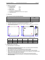
The cabinet should be mounted at a wall using the four holes on the brackets fastened to the
corners of the rear side of the cabinet. The cabinet must be fastened to the wall with 4 dowels and steel
screws. Due to the big weight (batteries) it is recommended the use of steel sleeve anchors and steel
screws.
The place of the mounting holes is included in the point 1.3 ‘Technical Description’.
2.3 Battery selection criteria
When selecting the battery capacity, for the determined battery backup time, please, take into
consideration the power supply quiescent current consumption, which is:
• 12V – 100mA
• 24V – 35mA
• 48V – 25mA
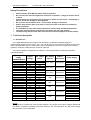
Selection of the battery capacity must be based on the size of the casing and an output voltage of
12V, 24V or 48V. In the table, the maximum capacity has been defined for each value of the output
voltage, separately for each of the three sizes of the casings.
In the modular power supplies mounted inside cabinets, the factory preset charging current is
equal to 25% of the nominal output current. An installer or a user can select higher charging current in
relation to the nominal output current (50%, 75% or 100%), especially for batteries with higher capacity
to shorten their charging time. It is important to use the tips in the User Manual. This setting does not
require dismounting the power supply but sliding the switch available on the bottom panel of the casing
from the front panel.
NOTE: please, take into consideration that the charging current must not exceed 30% of the
battery capacity.
2.4 Connecting
Please, note that the device must be connected to a fixed installation using the protective cable. It is
recommended to equip the installation with an anti-surge protection circuit. It is possible to lead the
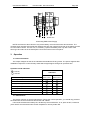
installation cables from the top through the PG11 glands (3 pcs.) and PG9 (1 pc.) located there. All
connections must be done according to the diagram located inside – on the cabinet door. If you do not
use one of the glands, its hole must be plugged with an additional cap delivered with the power supply.
The recommended cross-section of the 3-wire cable to connect the mains is 3 x 0.75 ... 1.5mm2.
The recommended output cable is LgY, which cross-section should be adapted to the value of the
output current and the distance from the receiver.
When connecting the remote indication it is recommended to use the 2-wire cable of the cross
section of 2 x 0.75mm2.
Please, insert the supplied temperature probe into the socket described TEMP PROBE and put it
next to the battery.
In addition, the potential-free relay indication contacts described MAINS FLT and BAT FLT are
accessible on the front panel of the power supply. To trigger the general fault indication, the both
terminals should be connected serially for the NO terminals or in parallel for the NC terminals. The
contacts are described on the figure on the front panel of the CAMELEON modular power supply, next
to the fault indication connector.