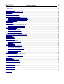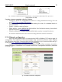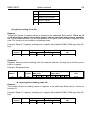
1
DATA LOGGER WITH WWW SERVER SM61 TYPE USER’S MANUAL 1 SM61-09C/1 User's manual 2 Contents: 1. Application........................................................................................................................................................... 3 2. Data logger set .................................................................................................................................................... 4 3. Basic requirements, safety of use........................................................................................................................ 4 4. Assembly............................................................................................................................................................ 5 4.1. Fixing way....................................................................................................................................................... 5 4.2. Electrical connections .................................................................................................................................... 6 4.3. Data logger configuration................................................................................................................................ 9 4.3.1. Configuration using USB interface ....................................................................................................... 11 4.3.2. Configuration using RS-485 interface................................................................................................... 12 4.3.3. Configuration using LAN interface........................................................................................................ 12 5. SM61Config software......................................................................................................................................... 13 5.1. Installation..................................................................................................................................................... 13 5.2. First start....................................................................................................................................................... 13 5.2.1. Selection of communication way.......................................................................................................... 13 5.2.2. First run using USB interface ............................................................................................................... 14 5.2.3. First run using LAN interface................................................................................................................ 15 5.3. Software functions........................................................................................................................................ 16 5.3.1. Main menu............................................................................................................................................ 17 5.3.2. List of SM61 devices............................................................................................................................. 17 5.3.3. Ethernet configuration........................................................................................................................... 18 5.3.4. Serial port configuration........................................................................................................................ 19 6. Web browser...................................................................................................................................................... 21 6.1. The beginning of work with the browser........................................................................................................ 21 6.2. Logging......................................................................................................................................................... 22 6.3. Overall look................................................................................................................................................... 22 6.4. Website menu............................................................................................................................................... 23 6.5. Administration............................................................................................................................................... 24 6.5.1. General settings.................................................................................................................................... 25 6.5.2. Date and time settings.......................................................................................................................... 26 6.5.3. Users.................................................................................................................................................... 26 6.5.4. Event log............................................................................................................................................... 27 6.6. Configuration................................................................................................................................................. 28 6.6.1. Channels configuration......................................................................................................................... 28 6.6.2. Alarms configuration............................................................................................................................. 33 6.6.3. Synoptic map configuration................................................................................................................... 36 6.6.4. Serial port configuration........................................................................................................................ 40 6.6.5. Ethernet configuration........................................................................................................................... 42 6.6.6. Archive uplaod...................................................................................................................................... 43 6.7. Data presentation.......................................................................................................................................... 44 6.7.1. Channels values presentation............................................................................................................... 44 6.7.2. Synoptic map presentation................................................................................................................... 46 6.8. Language change......................................................................................................................................... 47 7. FTP Client.......................................................................................................................................................... 47 8. Internal archive.................................................................................................................................................. 50 8.1. Archiving configuration.................................................................................................................................. 50 8.2. Downloading archive data............................................................................................................................. 51 8.3. Structure of archive files............................................................................................................................... 52 9. Alarms and binary inputs................................................................................................................................... 53 10. Interface RS-485.............................................................................................................................................. 54 10.1. Description of functions............................................................................................................................... 54 10.2. Error codes................................................................................................................................................. 56 10.3. Registers map............................................................................................................................................. 57 11. Technical data.................................................................................................................................................. 71 12. Ordering codes............................................................................................................................................... 72 13. Copyright.......................................................................................................................................................... 73 SM61-09C/1 User's manual 3 1. Application The SM61 data logger is meant to communication and archiving data in distributed measuring and control systems. It can service remote analogue and binary inputs/outputs modules, measuring transducers, inverters, microcontrollers, recorders, display panels, HMI panels etc. There are available two serial ports to the communication. PORT 1 is for communication with PC computer and HMI panels (RS-485, RS-232, USB), PORT 2 is for communication with such Slave devices (RS-485). The SM61 data logger reads and archives data from devices equipped with protocol Modbus RTU and serial interfaces (RS-485 or RS-232). Data exchange with main computer is done through computer network (Ethernet) with the use of network protocols (TCP/IP, FTP). The data logger has an innovative configuration and data presentation interface which is user friendly. It has an ability to monitor and configure through SM61Config software and through web browser. The data logger features: - possibility of simultaneous connection of two Modbus TCP clients, - up to 1 GB FLASH memory, - readout of up to 2500 values from Slave devices. The exemplary use of SM61 data logger in a local computer network is presented on fig. 1. Fig. 1. Exemplary use of SM61 SM61-09C/1 User's manual 4 2. Data logger set The set includes: 1. data logger SM61..................................................... 1 pc 2. quick start manual..................................................... 1 pc 3. guarantee card.......................................................... 1 pc 4. CD with the software and user's manual....................1 pc 3. Basic requirements, safety of use Symbols placed in the manual means: Especially important, you should know before you connect the data logger. Failure to follow the remarks could lead to damage of the data logger. Pay special attention if a data logger works inconsistently to your expectations Notice: The removal of the data logger casing during the guarantee contract period lead to its cancellation. Observations concerning the operational safety: All operations concerning transport, installation and commissioning as well as maintenance must be carried out by qualified, skilled personnel, and national regulations for the prevention of accidents must be observed. Before switching the data logger on, one must check the correctness of connections of the network. Before the remove of the casing one should switch off data logger power and measurement circuits. The device is destined to be installed and used in industrial electromagnetic environment conditions. A switch or a circuit - breaker should be located near the device, easy accessible by the operator and suitable marked. SM61-09C/1 User's manual 5 4. Assembly 4.1. Fixing way The SM61 data logger is fixing on rail bracket 35 mm. Dimensions and fixing way are shown at fig. 2. REC LAN Fig. 2. Dimensions and fixing way SM61-09C/1 User's manual 6 4.2. Electrical connections Power and external inputs should be connect according to the fig. 3 and table 1 in which is described destiny of the particular terminals in SM61 data logger. Terminals description of data logger Supply depend on the code version 85...253 V a.c., 90...300 V d.c. or 20...40 V a.c., 20...60 V d.c. or 10...16 V a.c., 10...20 v d.c. Terminal Diode signaling correct supply (green) or system error (red) - PWR diode Diode signaling reception/transmission of data on PORT 1 Diode signaling reception/transmission of data on PORT 2 Diode signaling correct (green) or incorrect (red) data archive LAN Table 1 Description 1 Input line (+ input 1) or line of alarm 1 2 Input line (- input 1) or line of alarm 1 3 Input line (+ input 2) or line of alarm 2 4 Input line (- input 2) or line of alarm 2 5 GND line 6 Line B (RS-485) 7 Line A (RS-485) 8 Line 5 V d.c. 9 Line + of power 10 Line - of power 11 not used 12 Output TxD (RS-232) 13 Output RxD (RS-232) 14 Line GND 15 Line A (RS-485) 16 Line B (RS-485) Fig. 3. Electrical connections of SM61 The SM61 has four communication interfaces: 1. PORT 1 - serial interface: • purpose - communication with Master device, • bus - RS-232, RS-485, • terminals - 14, 15, 16 (RS-485) and 12, 13, 14 (RS-232), • galvanically isolated from rest of the system, • maximum length of bus depends on the speed of transmission (for high speeds of up to several tens of meters, for small, e. g. 9600 bit/s to about 1.2 km). 2. PORT 2 - serial interface: • purpose - communication with Slave device, • bus - RS-485, SM61-09C/1 • • • User's manual 7 terminals - 5,6,7,8, galvanically isolated from rest of the system, maximum length of bus depends on the speed of transmission (for high speeds of up to several tens of meters, for small, e. g. 9600 bit/s to about 1.2 km). 3. USB - serial interface: • protocol of data exchange: Modbus RTU, • purpose - device configuration, • connection - mini USB. 4. LAN : • protocol of data exchange: Modbus TCP, • purpose - device configuration, • allow to connect device to Ethernet network (the way of connection shown on fig. 4), • connection - RJ-45. To connect SM61 to Ethernet network it is advisable to use a twisted-pair cable: • U/FTP – a twisted-pair cable with each pair on a separate screen with the film, • F/FTP – a twisted-pair cable with each pair on a separate screen in addition to filmscreen, • S/FTP ( formerly SFTP) – a twisted-pair cable with any pair foiled in addition to the screen mesh, • SF/FTP ( formerly S-STP) – a twisted pair cable with each pair twisted foil in addition to film and screen grid. SM61-09C/1 User's manual 8 RJ-45 socket Ethernet cable Fig. 4. Connecting Ethernet wire to RJ-45 socket The category of twisted pair according to European standard EN 50171 minimal: class D (category 5) – for fast local network, includes applications which uses the frequency band up to 100 MHz. Description of the connection is shown at table 2. For the interface Ethernet there should be applied a twisted-pair cable type STP (shielded) category 5 with a plug RJ-45 with cables colours (according to table 2) in the following standard: • EIA/TIA 568A for both connectors in simple connections SM61 to a hub or switch, • EIA/TIA 568A for first connector and EIA/TIA 568B for second connector in connection with crossover (connection SM61 to a computer). Wire colors in a RJ-45 plug Table 2 Wire Signal Wire color in accordance to standard No. EIA/TIA 568A EIA/TIA 568B 1 TX+ white - green white - orange 2 TX- green orange 3 RX+ white - orange white - green 4 EPWR+ blue blue 5 EPWR+ white - blue white - blue 6 RX- orange green 7 EPWR- white - brown white - brown 8 EPWR- brown brown After connection device to Ethernet network it is able to configure settings using HTTP protocol or Modbus TCP. SM61-09C/1 User's manual 9 The data logger set include CD with USB driver and software SM61Config, which is used to find devices in Ethernet network and configure them by Modbus RTU (USB) or Modbus TCP (Ethernet) protocol. Notice: To get full resistance of data logger on electromagnetic interference one should follow these rules: • do not supply the data logger from the network which is near pulse noise generators (inverters) and do not use common with them grounding circuits; • use network filters; • all shields should be grounded or connected to the protective unit, one sided the nearest to the data logger; • use the general rule, the wires leading different signals should be carried out in the greatest distance from each other (no less then 30 cm), the intersection of these beams is performed at 90. 4.3. Data logger configuration Notice: First run of a device requires configuration of basic parameters. Delivered device has default settings presented in table 3: SM61-09C/1 User's manual 10 Default settings Table 3 PORT 1 RS-485 Address 1 Mode RTU 8N1 Baud rate 9600 bit/s PORT 2 RS-232 Mode RTU 8N1 Baud rate 9600 bit/s RS-485 Mode RTU 8N1 Baud rate 9600 bit/s USB Address 1 Mode RTU 8N1 Baud rate 115200 bit/s LAN LAN interface IP Address 192.168.1.1 Mask 255.255.255.0 Gateway 0.0.0.0 LAN speed Auto Modbus TCP Address 255 Port 502 Ports TCP/IP HTTP 80 FTP command port 21 FTP data port 22 Search 2323 Running of SM61 comes in two stages. In the first stage the procedures of testing and configuration reading in the activated SM61, are initiated. First, the device makes a test of external memory. If the test result is not carried out correctly, the device will restart. After correct testing, the configuration data are read out. The configuration data readout error is signaled by switching on of a red diode PWR (fig. 3) and a proper setting of an error status value (table 21). The error of configuration readout imposes the setting of default data presented in the table 3. After configuring basic communication parameters, Modbus RTU for USB interface and RS-485/232 for Slave mode is activated. SM61-09C/1 User's manual 11 Then the device launches the next stage - the readout of channels configuration for Master RS-485. The configuration readout lasts for about 20 seconds and is signaled by switching on of REC diode (fig. 3) in green color. The occurrence of a configuration readout error disconnects the data readout and is signaled by switching on of a red diode PWR (fig. 3) and a proper setting of an error status value (table 21). The readout of the whole configuration imposes launching of remaining modules, such as: • LAN module, • Modbus RTU module for Master mode, • archive module, • alarms module, • statistical data operation module. After reading the configuration, the device is ready for further work. At first run, the data logger is using default settings. However, right after the first activation the data logger configuration ought to be carried out in order to prepare it for work at a defined environment. Configuration may be carried out using: • USB (VIRTUAL PORT COM, Modbus RTU), • PORT1 (RS-485, Modbus RTU), • LAN (Modbus TCP, HTTP). 4.3.1. Configuration using USB interface In order to configure the device through USB interface, the device ought to be connected with the mini USB cable to PC. After connecting a data logger, the operational system will notify of the occurrence of a new device by displaying a message presented in fig. 5. Found New Wizard of Universal Serial Bus will activate automatically. Wizard’s suggestions ought to be followed by selecting installation from the indicated localization and giving a tract for drivers, which can be found on an attached CD. Drivers are compatible with the following systems: Windows 2000, XP, Server 2003, Vista, Windows 7, Server 2008 (x86 and x64). At drivers installation, a message signaling lack of drivers digital signature can occur. Ignored them and proceed with further installation. Fig. 5. Message signaling detection of new device Data logger/Logger SM61 After closing the wizard, the system will immediately detect another device - USB Serial Port (fig. 6). Found new hardware wizard will be restarted. During the installation process, all wizard suggestions ought to be followed. Fig. 6. System message on finding new device After successful installation, the system will notify on installing a new device (fig. 7). Two new devices will appear in Device Manager - Data logger/Logger SM61 and Port COM named: data logger/Logger SM61, according to fig. 8. SM61-09C/1 User's manual 12 Fig. 7. System message finishing drivers installation of SM61 Succccessful instaled SM61 device with virtual port COM25 Fig. 8. Device manager window with installed SM61 with assigned port No. COM25 Then SM61Config software on attached CD ought to be run and installation procedures with user guide for first application run ought to be followed, point 5. SM61Config software. After entering configuration it ought to be saved and the device restarted so that a new configuration can be entered. Notice: After changing the parameters the device should be reset. 4.3.2. Configuration using RS-485 interface In order to configure the device by interface RS-485, the device ought to be connected using a converter (e.g. PD 10) to a PC. Then in accordance with tables 19 and 20 from point 10.3. Registers map, which contains registers map of SM61, using own program or a device compatible with Modbus RTU do the data logger configuration. 4.3.3. Configuration using LAN interface In order to configure the device by LAN interface, the device ought to be connected to the Ethernet network. Then SM61Config software on attached CD ought to be run and SM61-09C/1 User's manual 13 installation procedures from user guide for first application run ought to be followed, point 5. SM61Config software. Notice: After changing the parameters the device should be reset. In case of problems it is advised to restore default parameters and restart configuration, in accordance with points 4.3.1-3. Restoring default parameters can be done: • during device operation time by pressing the button located in the upper part of the casing, • by selecting “Default Settings” in the program “SM61Config” (see point 5. SM61Config software). 5. SM61Config software The SM61Config software allows for searching all data loggers in Ethernet network and to configure a selected SM61 device using protocol Modbus RTU (interface USB) or using protocol Modbus TCP (LAN interface). The SM61Config also allows for downloading archive files from data logger using FTP protocol. To apply any changes in configuration of the data logger it is required to enter the password for the administrator account. Default administrator password is: dbps For more information about users, see point 6.5.3. Users. 5.1. Installation Installation program is found on CD attached to SM61. To run an installation on a computer, the software SM61Config_install_v_X_X_X.exe should be started. This is an application that installs SM61Config with essential accessories on a user’s computer. During installation one ought to proceed in accordance with the instructions displayed on the screen. 5.2. First start At first start of SM61 it is required to configure basic IP settings, such as: – IP address, – subnet mask, – default gateway address. Needed information should be given from local network administrator in which device will be joined. The SM61Config software enables the user to configure network setting of SM61 by USB interface or by Modbus TCP (LAN interface, Ethernet). 5.2.1. Selection of communication way After installing the application one ought to run it. The default communication with device is Modbus TCP. After starting application the searching devices window appears. Then select the way of communication with the device, from the software menu (Option -> Communication), fig. 9. SM61-09C/1 User's manual 14 Fig. 9. Selection of communication way from the device Then proceed to the further configuration. 5.2.2. First run using USB interface After selecting communication way, proceed to list of devices (show devices connected via USB – fig. 10). Fig. 10. List of devices connected via USB After selecting device by left-click on proper line of list one can go to configuration by selecting a proper option from the menu (presented in fig. 11). Configuration of the Ethernet settings Configuration of the serial port Fig. 11. Left menu options Configuration of individual settings is described in points 5.3.3. Ethernet configuration and 5.3.4. Serial port configuration in further part of the user’s manual. After right-click on the appropriate line of the list the context menu appears (shown in fig.12). Fig. 12. Context menu searching via USB SM61-09C/1 User's manual 15 Notice: After changing the parameters the device should be reset. 5.2.3. First run using LAN interface After selecting the communication way with the device, open the SM61Config and display the list of searched devices connected to Ethernet network by selecting the option List of SM61 device from the menu shown in fig. 13. The list of searched devices Ethernet configuration Serial port configuration Download the archive files Fig. 13. Left menu options of SM61Config After left click on a selected device from the list of searched data loggers, new context menu presented on the fig. 14 Will appear. Fig. 14. Context menu allowing for IP settings change Selecting Change IP causes the appearance of window that enables for configuration of the following settings (fig. 15): SM61-09C/1 User's manual 16 Fig. 15. Change of IP settings After entering changes, clicking OK will cause the window to shut down and will save the changes in the device memory. Notice: After changing the parameters the device should be reset. 5.3. Software functions After opening of the software the window presented on the fig. 16. It is possible to open only one application window. Fig. 16. General appearance of SM61Config SM61-09C/1 5.3.1. Main menu User's manual 17 Main menu presented on the fig. 17 enables: 1. File • Exit - close software. 2. View • Status bar - show or hide status bar. 3. Options • Languages - language change. • Communication - allows for the change of communication way with the device. There are two ways of communication: USB (USB interface) and Modbus (LAN interface). Selecting an USB option requires connecting the device to the USB port and does not require selecting the device from the list. Selecting Modbus TCP option requires, for the sake of further work, selecting the device from the list. Communication via Modbus TCP is set as default. 4. Help • About - information about software version. Fig. 17. Structure of the main menu 5.3.2. List of SM61 devices Selecting an option List of SM61 devices allows for searching existing devices in Ethernet network or devices connected via USB (fig. 18). Fig. 18. Searched data loggers Selecting a device for configuration is done by left click on an IP address of a chosen device. Then the whole line will highlight in a way presented on the fig. 18. After selecting a device, move forward to its configuration by selecting a right option (Ethernet or Serial Port). Right click on an IP address of a selected device causes displaying of context menu presented on the fig. 19. SM61-09C/1 User's manual 18 Fig. 19. Menu invoked with a right click (left menu – communication via Modbus TCP, right menu – communication via USB) Functions of menu presented on the fig. 19 allow: • Change IP - allows for configuration of a device in a way presented on the fig. 15 in the point 5.2.3. First run using LAN interface. • Go to www - selecting this option causes moving to a site of a selected device in Internet browser. • Restart - causes a restart of device. • Delete archive - auses deleting the whole archive from the device memory (more about archive in the point 8. Internal archive). • Default configuration - causes restoring default data, requires to restart the device. All activities described above are carried out using Ethernet network connection. 5.3.3. Ethernet configuration One of the two possible ways of communication (USB or Modbus TCP) can be used for configuration. The selection of the communication way proceeds as follows: select Options from the main menu then Communication and from submenu way of communication as fig. 9 in the point 5.2.1. Selection of communication way presented. In case of selecting communication by Modbus TCP, it is first necessary to select a device with which a connection is to be made from the list. Configuration window is presented on the fig. 20. Fig. 20. Window of Ethernet configuration SM61-09C/1 User's manual 19 Parameters presented on the fig. 20 are described in the table 4. Parameters describe Name Description Table 4 Name device name, maximum 8 characters Description device description, maximum 20 characters DHCP on or off DHCP IP Address IP Address, address i fourth version Ipv4 Subnet mask subnet mask Gateway device gateway MAC Address address MAC, MAC is given in such a format XX:XX:XX:XX:XX:XX Baud rate baud rate: - auto (defalut) - 10Mbit - 100Mbit Web server port number of web server port, values from 80 (defalut) to 65535 FTP server data number of FTP server data port, possible values from port 20 to 65535 (default value 22) FTP server number FTP server command port, possible values command port from 20 to 65535 (default value 21) After entering changes, select Save configuration. After saving the configuration the information on successful or unsuccessful entry will be displayed. In the case of communication with a device using USB, the saving procedure may take more time than in the case of communication using Modbus TCP (Ethernet network). Notice: After changing the parameters the device should be reset. There is a possibility of re-loading of configuration by Load configuration. In the case of selecting communication using USB, there is an additional possibility to set default MAC Address (fig. 21). Fig. 21. Setting of default MAC Address 5.3.4. Serial port configuration For serial port configuration, like in the case of Ethernet configuration, one of the two possible ways of communication (USB and Modbus TCP) can be used. The selection of the SM61-09C/1 User's manual 20 way of communication is presented on the fig. 9 in the point 5.2.1. Selection of communication way. Configuration window is presented on the fig. 22. Fig. 22: Serial port configuration Parameters presented on the fig. 22 are described in the table 5. Parameter description Name Description Table 5 Modbus Master Bud rate Modbus Master transmission speed can assume the following values: 1200bit/s, 2400bit/s, 4800bit/s, 960bit/s, 19200bit/s, 38400bit/s, 57600bit/s, 115200bit/s Transmission mode Modbus Master transmission mode, two following values are possible: 8N2, 8E1, 8O1, 8N1 Modbus Slave Device Address Device address can assume values from 1 up to 255 Baud rate The same like for Modbus Master Transmission mode The same like for Modbus Master Modbus Slave TCP Address The same like for Modbus Slave TCP Modbus port number TCP Modbus Port Number can assume values from 10 up to 100 (default port number) Number of simultaneous connections with TCP Modbus Maximum number of simultaneous connections (possible setting from 1 to 4 simultaneous connections) TCP port closing TCP port closing time, possible values from 10s time up to 600s SM61-09C/1 User's manual 21 After entering changes, select Save configuration. After saving the configuration the information on successful or unsuccessful entry will be displayed. In the case of communication with a device using USB, the saving procedure may take more time than in the case of communication using Modbus TCP (Ethernet network). Notice: After changing the parameters the device should be reset. There is a possibility of re-loading of configuration via Load configuration. In the case of selecting communication using USB, configuration window looks exactly the same like for communication via Modbus TCP. 6. Web browser The data logger makes its own WWW server available to monitor and configure measurable values and a device condition. SM61 site enables to: – obtain information on a device (serial No., name, etc.), – view of current measurable values, – configure data logger settings. Notice: For proper working of web site one need to have the browser with JavaScript enabled and compatible with XHTML 1.0 (all popular browsers, Internet Explorer version minimum 8). 6.1. The beginning of work with the browser At its first run, the SM61 requires the setting of protocol IP essential information, such as: – own IP address, – network mask, – default gateway address. Needed information should be given from local network administrator in which device will be joined. SM61 first run ought to be carried out in accordance with point 4.3. Data logger configuration. To obtain access to server it is required to connect SM61 to Ethernet working in accordance with the TCP/IP protocol. The access to server is gained through entering data recorder IP address in the web browser, e.g.: http://192.168.1.1 (where 192.168.1.1 is data logger default address). One can also use web browser call in SM61Config software, which is presented on the fig. 17 in the point 5.3.2. List of SM61 devices. SM61-09C/1 User's manual 22 6.2. Logging To start work with a browser it is necessary to be logged at the site. User’s login and password need to be entered. SM61 has a default user: – login: root – password: dbps For safety reasons, after the first run of browser the logging and the password ought to be changed into different than default ones, (see point 6.5.3. Users). 6.3. Overall look After logging in the main site presented on the fig. 23. Main menu Left menu Fig. 23. Homepage There are the following elements of the site: a) The top menu of the site (fig. 24): Fig. 24. Top menu Detailed description of menu in the point 6.4. Site menu. b) Logout and language change option (fig. 25): Fig. 25. Change of language and user’s logout SM61-09C/1 User's manual 23 Language change option is described in the point 6.8. Language change. Logout option logs out the user. c) Left menu (fig. 26): Fig. 26. Left menu The content of the left menu depend on the option selected from the top menu. For all possible options the fixed element that appears in the left menu is general information about device, such as: – name, – IP Address, – name of the logged user, – the amount of an occupied area in data logger memory in percentage. d) Main part of the site (fig. 27): Fig. 27. Main part of the site This element of the site changes according to the option selected from the top menu. 6.4. Website menu The structure of the top menu of the site is presented on the fig. 28: SM61-09C/1 User's manual 24 Fig. 28. The structure of the top menu of the site The site menu consists of the following elements: a) Home - contains general information on module. b) Data presentation – contains the following elements: - Channels values - contain the presentation of values loaded from the device, presented as a table and as a chart (point 6.7.1.Presentation of channels values), - Synoptic map - contains the presentation of the current synoptic map (point 6.7.2. Presentation of synoptic map). c) Configuration- consists of the following elements: - Channels - allows for configuration of all channels and their values (point 6.6.1. Channel configuration). - Alarms - allow for alarms configuration (point 6.6.2. Alarms configuration), - Synoptic map- allows for synoptic map configuration (point 6.6.3. Synoptic map configuration), - Serial port - allows for serial port configuration (point 6.6.4. Serial port configuration), - Ethernet - allows for Ethernet settings configuration (point 6.6.5. Ethernet configuration). - Archive upload - archive files from the device are automatically sent to the remote FTP server (point 6.6.6. Archive upload) d) Administration - contains the following options: - General - allows for the change of name and device description, the change of records number in an archive file, archive mode and setting of starting page (point 6.5.1. General settings), - Date and time - allows for the change of date and time in a device (point 6.5.2. Date and time setting), - Users- allows for the change of login and password (point 6.5.3. Users). - Event log - displays information from the device about his work (point 6.5.4. Event log). e) Restart device - allows for device restart, after the restart configuration is reloaded. f) Reload page – allows reload page. 6.5. Administration The SM61 data logger allows for time synchronization by web browser. Option Administration allows for both time synchronization and users' accounts management. Going to Administration is presented on the fig. 29. SM61-09C/1 User's manual 25 Fig. 29. Top menu - administration 6.5.1. General settings To go to general settings select option Administration from the main menu and then from the submenu which is displayed select General in a way presented on the fig. 29. General settings possible for configuration are presented on the fig. 30 and in table 6. Fig. 30. General settings General settings description Name Description Table 6 Device name may contain maximum 8 characters Device description may contain maximum 20 characters Active channels how many channels from available 100 to use, affect performance Number of records in from 20 up to 32000 archive file Archive mode following cases are possible: - archiving able - archiving disable - archiving invoked by A1 (for device alarms – alarm 1) or by B1 (for device inputs) - archiving invoked by A2 (for device alarms – alarm 2) or by B2 (for device with with with with SM61-09C/1 User's manual 26 inputs) Session expiration time this is the time after which the user will be logged out from the site, a choice of values: -1 minute -5 minutes -30 minutes -1 hour - 5 hours Starting page there are three possibilities: - homepage - values - synoptic map 6.5.2. Date and time settings To set time and date choose option Administration from menu and then from submenu choose option Date and time, according to fig. 32 in the point 6.5. Administration. Data logger allows for the change of date and time, the window enabling for date and time configuration is presented on the fig. 31. Fig. 31. Date and time settings 6.5.3. Users To go to users settings choose option Administration from the menu and then choose option Users from the submenu according to fig. 32 in the point 6.5. Administration. Selecting the option Users displays the list of all users, presented on the fig. 32. Fig. 32. List of users There are two types of users accounts: – administrator's account, – normal account . Administrator has an access to a device configuration and to users accounts configuration. The normal account does not allow for changes in users accounts and does not have the option Administration in the menu. Administrator's account is the only one. The other accounts are of normal type. SM61-09C/1 User's manual 27 Option Add new (fig. 35) allows for adding a new user, giving a new user its name and password and defining an account type. Right click on one of the users name from the list displays a context menu presented on the fig. 33. Fig. 33. Users options menu Option Edit allows for editing user's settings and entering changes. The window editing a user is presented on the fig. 34. Fig. 34. User's data edition 6.5.4. Event log Event log tab displays information about the unit, as shown in fig. 35, it is information how to create files, save the configuration, turn on the device. The list of events can be refreshed or deleted by selecting the appropriate button positioned above the list of events. Fig. 35: Event log from device SM61-09C/1 User's manual 28 6.6. Configuration Notice: Data logger requires configuration. It is absolutely necessary to reset the device after parameters change. 6.6.1. Channels configuration The SM61 data logger has maximum 100 virtual channels, one channel has maximum 25 values. Values include measurable data delivered by registers. To go to channel configuration choose option Configuration from the menu and then option Channels from the submenu that will be displayed, as it is presented on the fig. 36. Fig. 36. Channels configuration Then the site presented on the fig. 37 displays: Fig. 37. Site view with channels configuration SM61-09C/1 User's manual 29 The left menu contains data logger general data and the option of channel selection which are to be displayed in the main part of the site. The following options are available : a) All - all channels are displayed, b) Active - he option displays channels with the channel mode set on: • monitored, • archived, • full, c) Monitored • monitored, • full, d) Archived • archived, • full, e) Turned off - the option displays channels with the channel mode set on- turned off. Displaying all channels is a default setting (regardless the work mode that is set on), they are displayed at the number of 25 on one site (fig. 39). The number of channels displayed on a site can be changed in a way presented on the fig. 38. Entering a number in a marked place, e.g. 25 and pressing Enter, displays a defined number of channels on a site. Fig. 38. Setting the number of channels displayed on a site Graphic signs using in channels configuration are presented in the table 7. The table presenting channels contains only selected information on a channel e.g.: – channel number, – name of the first channel value, – channel mode, – device address, SM61-09C/1 User's manual 30 – base register address, – register size, – registers type, – polling interval, – archiving interval, – device timeout, – number of values, – an icon informing whether the channel is active ( ), To go to a selected channel right click on a number of a selected channel and choose Edit from the context menu presented on a the fig. 39. Option Copy allows for copying the configuration from the other channel. Fig. 39. Context menu After selecting the option Edit the view containing all information about selected channel and its values is displayed. The view containing information about a channel is presented in the fig. 40. Fig. 40. Channel configuration Parameters displayed on the fig. 40 are described in the table 8. SM61-09C/1 User's manual Channels settings Name 31 Table 8 Description Channel mode the mode of a selected channel: - turned off, - monitored, - archived, - full (monitored and archived), setting archived and full mode will make all values of a given channel archive in a file- details on archiving (see point 8. Internal archive) Source type data source for a channel: - Modbus RS (Modbus Slave device), data is loaded from Modbus Slave device, - internal (constant or values from other channel), internal data of a device constitute the data source Device address values from 1 up to 255 Base register address register address that contains data loaded from a device connected to a data logger Register size the size of polling registers in bites (16 or 32 bites), all registers are 16-bite size except: - long, - ulong, - float, which can be set ether as 16 or 32-bite size Registers type sets the register type in a channel: - char – 16 bites - character data type (two characters ASCII), - uchar - unsigned char- 16 bites - character data type (two characters ASCII), - short - 16 bites (values ranging from 32768 to 32767), - ushort- unsigned char - 16 bites (values ranging from 0 to 65535), - long - 32 bites or 2x16 bites (values ranging from - 2147483648 to 214748647), - ulong - unsigned long - 32 bites or 2x16 bites (values ranging from 0 to 4294967295), - float1234 - 32 bites or 2x16 bites, a floating - point number, the least significant bite on the first position, - float4321 - 32 bites or 2x16 bites, a floating point number, the least significant bite on the last position Pooling interval value from 1 to 65535 Archiving interval value is active when the mode is archived or full, may assume values from 10 up to 65535 Device timeout values from 1 up to 65535 The table with channel values displays while editing a channel, fig. 41. SM61-09C/1 User's manual 32 Fig. 41. Editing channels value Right click on a number of a selected value displays a context menu presented on the fig. 42. Fig. 42. Context menu Selecting the option Add here adds a new value in the place of a highlighted value (the highlighted one goes to the next position), the option Delete deletes the highlighted value. Values properties which can be configured are presented in the table 9. Values settings Name Description Table 9 Value number values from 1 up to 25 Value name the name consists of maximum 15 characters Register address automatically calculated based on base register Unit presents available units Mathematical operations Mathematical operator +, -, /, *, = Argument of mathematical operations values from 1 up to 214748,36 Mathematical operations with other channels Mathematical operator +, - , / , *, = Channel number channel number is used for operations with other channels Value number value number of previously selected channel used for mathematical operations with other channels mathematical It is possible to carry out mathematical operations on configured channel values. Mathematical operations with a quoted argument or selected value from a selected channel can be carried out on the values. After configuring a single channel, all settings ought to be saved. Saving the channel will cause saving the configuration of a single channel only to a volatile memory which will not be recalled after the device restart. For the configuration to be remembered after the computer restart, go from channel edition to the view of all channels (button - green arrow in left) and save the configuration. SM61-09C/1 User's manual 33 Setting mathematical operations for the value will cause carrying out a mathematical operation on a value being downloading from a device. Notice: After changing the parameters the device should be reset. 6.6.2. Alarms configuration Alarms configuration is available to implementation with alarms, for implementation with binary inputs there is no this site element. Moving to alarms configuration is presented on the fig. 43. Fig. 43. The way of going to alarms configuration After the site downloads, the window presented on the fig. 44 will display. The data logger SM61 allows for setting of twenty five alarms. Each of them have the same set of parameters to be configured. Alarms parameters are presented in the table 10. For each alarm it is possibly to send email with information about its occurrence. To send a message, one must specify proxy credentials to the SMTP server. It is recommended that the server was located in the same network with the device. Notice: Intermediary SMTP server must support AUTH PLAIN authentication after unencrypted connection (usually port 25). SM61-09C/1 User's manual 34 Fig. 44. Alarms configuration When configured to send e-mails to several alarms it is recommended to check the option Group Messages. In this manner, in the case of the simultaneous occurrence of multiple alarms, it will be sent only one message, thereby excessive load on the server will be avoided. Each sending a message is recorded in the event registry. Also in case of problems with the delivery of messages, relevant information about the error are saved. Alarms parameters Name Description Table 10 Trigger source alarm trigger sources; - none (lack of the alarm) - channel value - configuration error - archiving error - lack of space in FLASH memory - memory filled in 80% - always turned on Channel number channel number applicable to an alarm, active when channel value is the trigger source Value number channel value number that applies to an alarm, active when channel value is the trigger source SM61-09C/1 User's manual Alarm type 35 - n-on (alarm sets when the value rises above the upper level and turns off when it drops below the lower level) - n-off (alarm turns off when the value rises above the upper level and turns on when it drops below the lower level) - on (when value within the range alarm on, when outside the range alarm off) - off (when value in the range alarm off, when outside the range alarm on) Lower alarm lower alarm threshold, max. 32500000 can be threshold set Upper alarm upper alarm threshold, max. 32500000 can be threshold set ON delay max. value is 1000s OFF delay max. value is 1000s Set relay allows you to set the relays for alarm, a choice of two relays Send mail allows you to send an email to the above table email address. You can send one email to all alarms After entering changes they ought to be saved. When an alarm is on, a bell symbol with the applicable alarm number is displayed on a site (fig. 45), left click on it cause information about the alarm (fig. 46), that contains the following data: – number of alarm which is displayed, – alarm trigger source. Fig. 45. Information about the alarm Fig. 46. Information about the alarm More information on alarms in the point 9. Alarms and binary inputs. SM61-09C/1 User's manual 6.6.3. Synoptic map configuration 36 Moving to synoptic map configuration is in accordance with fig. 47. Fig. 47. The way of moving to synoptic map configuration After the site downloads, the window presented on the fig. 48 displays: Fig. 48. Edition of synoptic map configuration On the left side of the window there is the menu allowing for creating and configuring of a synoptic map. The menu divides into the following parts: a) Background files - the element presented on the fig. 49 allows for setting a background file of a map. SM61-09C/1 User's manual 37 Fig. 49. Selection of files background Positioning the mouse cursor on a question mark displays information on how to load your own background files (fig. 49). In order to load your own background file, send your image files using FTP client to “WWW/bitmaps” catalog. Servicing FTP client is presented in point 7. FTP Client. After selecting a file, chose Set which displays the selected background on the site. Elements described in b) can be applied on the set background file. b) Elements – the part of the left menu presented on the fig. 50, allows for applying new elements on the map. Fig. 50. Elements of synoptic map To add an element, select Add. The added element displays on the map in a way presented on the fig. 51: Fig. 51. Element on a synoptic map The element can be randomly moved on the map. Maximum 15 elements can be placed on the map. An active element is highlighted. By using navigation arrows you can choose which element is to be active. c) Selected item- the part of the left menu presented on the fig. 52 contains the information on an active (selected) item: SM61-09C/1 User's manual 38 Fig. 52. The left menu of synoptic map- selected item Channel number and value number of a channel which is to be represented ought to be selected for an item. Numbers can be filled manually or by using a help as presented on the fig. 53: Fig. 53. Selecting a channel and value for an item Selecting a value and clicking Ok fills values in the place of channel number and value number. An element can be moved by grasping an item with a mouse and inserting it in the right place. While moving it, current coordinates values are displayed. There is also a possibility to set a yellow or a transparent background for an element (using an option Show background), fig. 54: Fig. 54. Setting background for element Element can be deleted by clicking Delete. d) Load/ save map - allows for saving a map and loading a previously saved synoptic map (fig. 55). SM61-09C/1 User's manual 39 Fig. 55: Left menu of synoptic map - map loading and saving If there are any created synoptic maps they can be opened by selecting a map from the list and clicking Set. The map can be deleted by clicking Delete. The map can be also saved by entering a name that is not longer than 8 characters (containing only letters, numbers and underliners) and clicking Save. Selecting Refresh will refresh the list of maps. Right click on the main part of the site displays the context menu presented on the fig. 56: Fig. 56. Context menu of synoptic map Selecting Add new adds a new element. Selecting Clear all deletes all elements and a background from a synoptic map. Selecting Resize displays a window presented on the fig. 57 that allows for changing size of a synoptic map. Fig. 57. Map resizing Map size can be changed be entering width (maximum 2500 pixels) and height (maximum 1600 pixels) or by choosing the option Adjust to selected background file which enters given values. Right click on an element displays the menu presented on the fig. 58: Fig. 58. Context menu of synoptic map element Selecting Add new will add a new element to a map, selecting Assign channel will display a window allowing for selecting a channel value from the list of configured ones. Selecting Delete will delete a selected element. SM61-09C/1 User's manual 40 6.6.4. Serial port configuration Serial port configuration allows for configuring such settings as Modbus Master, Modbus Slave and Modbus TCP Slave. Going to serial port configuration is done by selecting Configuration from the site main menu and then Serial port from submenu according to fig. 59. Fig. 59. Serial port configuration After the site downloads its main part looks in the way presented on the fig. 60. Fig. 60: Looks of serial port configuration Modbus Master configuration allows for setting baud rate and transmission mode (table 11). Modbus Master settings Name Description Table 11 Baud rate Modbus Master baud rate, can assume the following values: 1200 bit/s,2400 bit/s, 4800 bit/s, 9600 bit/s, 19200 bit/s, 38400 bit/s, 57600 bit/s, 115200 bit/s Transmission mode Modbus Master transmission mode, the following values are possible 8N2, 8E1, 8O1, 8N1 SM61-09C/1 User's manual 41 Modbus Slave configuration allows for setting device address, baud rate and transmission mode (table 12). Modbus Slave settings Name Description Table 12 Device address Device address, can assume values from 1 up to 255 Baud rate Modbus Slave baud rate, can assume the following values: 1200 bit/s, 2400 bit/s, 4800 bit/s, 9600 bit/s, 19200 bit/s, 38400 bit/s, 57600 bit/s, 115200 bit/s Transmission mode Modbus Slave transmission mode, the following values are possible 8N2, 8E1, 8O1, 8N1 Modbus Slave TCP configuration allows for the settings of: – device address, – Modbus TCP port number, – number of simultaneous connections with Modbus TCP server, – TCP port closing time. The description of the above parameters is presented in the table 13. Modbus Slave TCP settings Name Table 13 Description Device address device address can assume values from 1 up to 254 Modbus TCP port number Modbus TCP port number, can assume values from 10 to 1000 Maximum connections simultaneous maximum number of simultaneous connections with Modbus TCP server, possible values from 1 up to 4 Port TCP closing time setting port TCP closing time, possible values from 10 s up to 600 s After changes one should left click Save to save all changes. Notice: After changing the parameters the device should be reset. 6.6.5. Ethernet configuration Ethernet configuration allows for configuring IP settings and ports settings. Going to Ethernet configuration is done by selecting Configuration from the main menu and then selecting Ethernet form the submenu, according to fig. 61. SM61-09C/1 User's manual 42 Fig. 61. Ethernet configuration After the site downloads, the configuration window presented on the fig. 62 displays. Fig. 62: The view of Ethernet configuration In IP settings it is possible to configure the values presented in the table 14. IP settings Name Table 14 Description IP address IP address, address is in the fourth version IPv4 Subnet mask subnet mask Default gateway default gateway MAC address MAC address, MAC address is quoted in the format XX:XX:XX:XX:XX:XX Transmission rate transmission rate on one of the options: - auto - 10Mbit - 100Mbit DHCP It is possible to configure: – web server port, – FTP server command port, DHCP On or Off SM61-09C/1 – – User's manual 43 FTP server data port, number of device serving port. Description of parameters is presented in the table 15. Ports settings Name Table 15 Description Web server port number of web server port, possible values from 80 up to 65535 FTP server command port number of FTP server command port, possible values from 20 up to 65535 FTP server data port number of FTP server data possible values from 20 to 65535 port, Device searching port number of device searching port, possible values from 10 up to 65535 After inserting changes they ought to be saved by clicking Save. Notice: After changing the parameters the device should be reset. 6.6.6. Archive uplaod Archive upload allows to transfer files archived on remote FTP server. Going to archive upload is done by going to Configuration from the main menu and then selecting the Archive uplad as shown in fig. 63. Fig. 63. Archive upload selection The view of channel values presentation is presented on the fig. 64. SM61-09C/1 User's manual 44 Fig. 64: Archive upload presentation To send files via FTP specify the IP address of the remote server and the directory path and the username and password. Archive files will be sent only after filling. 6.7. Data presentation Data presentation allows for browsing the current data being loaded from SM61 data logger. Data presentation is possible after prior proper device configuration. The measurement value in a given channel is the last correct value read out from the device. 6.7.1. Channels values presentation Moving on to channels values presentation is done by selecting Data presentation from the main menu and then the option Channel values from the submenu as presented on the fig. 65. Fig. 65. Channel values presentation The view of channel values presentation is presented on the fig. 66. Fig. 66: Channel values presentation SM61-09C/1 User's manual 45 It is possible to control the data presentation using the option of the left menu of the site as presented on the fig. 66. The menu contains the following elements: – Configuration – allows for refreshing the configuration, – Refreshing – allows for setting the values refreshment on a site. Available values: 2s, 5s, 10s and 60s and STOP to stop data downloading. – Last measurement – presents the time of last measurement made, the sign is green during read out, when refreshing is set on STOP the sign will turn red, – Chart – clicking on Show displays the chart. The table presented on the fig. 66 contains the following information: – channel number from which data will be downloaded, – value number of a given channel, – device address from which data is downloaded, – register address, – register type, – value name, – value - current value with a unit, when refreshing is not turned on this column is empty, the value appears after turning on refreshing, – add to the chart - highlighting this option adds a selected value to the presentation on the chart, – status. In case a channel has more than one value it is possible to collapse the view so that only the first channel value can be visible (fig. 67). Fig. 67: Collapsing of channel values The chart presents the values highlighted with the option Add to the chart. The chart is presented on the fig. 68. The chart presents last 30 values. The chart has its legend. After placing a mouse cursor on a value it becomes highlighted and the information containing basic data on a given value is displayed, these are: – name, – size, – downloading time. SM61-09C/1 User's manual 46 Fig. 68: Value chart 6.7.2. Synoptic map presentation Moving on to synoptic map presentation is done by selecting Data presentation from the site main menu and then Synoptic map as presented on the fig. 69. Fig. 69. Synoptic map presentation The view of channel values presentation is shown on the fig. 70. Fig. 70: Synoptic map presentation SM61-09C/1 User's manual 47 At first select a saved synoptic map and click Set (fig. 70). Then set refreshing which is set by default on STOP, it can be set on 2s, 5s, 10s, 60s. After setting the time of data refreshing, current data being downloaded from a device will start appearing on the site. The left menu also displays the time of last measurement, during downloading it displays in green, after downloading is off, it displays in red. Placing a mouse cursor on an element displays a window presenting such information on an element as: – name, – channel number, – value number, – unit. 6.8. Language change The change of a language is done by selecting a flag that represents a language (fig. 71). An active language version is presented by a colourful flag, inactive version by a black and white flag. Fig. 71. Language change 7. FTP Client The SM61 data logger enables communication by FTP protocol. You can get to files using standard program of FTP protocol client, website (to download archive files) and using SM61Config software (to download archive).To connect with a device using FTP client you need: - IP address - IP address setting is described in point 6.6.5.Ethernet configuration, - number of FTP server command port - setting a port number is described in point 6.6.5. Ethernet configuration, - number of FTP server data port - setting a port number is described in the point 6.6.5. Ethernet configuration, - user name and password - a user set by default (the same as for Internet browser) : login: root password: dbps For safety reasons a user ought to be changed for other than a default one, which is presented in the point 6.5.3. Users. The example of making a connection using FileZilla client (you can download FileZilla from http://filezilla-project.org) is presented on the fig. 72. SM61-09C/1 User's manual 48 Fig. 72: Making connection with FTP server For data transmission, maximum one connection at the same time is possible (in FileZilla a new site ought to be added and a number of simultaneous connections ought to be set on onefig. 73). Copying is to be done in a binary mode. Fig. 73: Setting a limit of connections in FileZilla The SM61 data logger has a folder structure presented on the fig. 74. SM61-09C/1 User's manual 49 Fig. 74: Catalog structure Individual folders contain: - DATA - contains files with archive data, - LOG - contains files with logs, - SYSTEM - contains files with configuration, - WWW - contains files with web site. 8. Internal archive The SM61 allows to store data read from Slave devices. Current data read from channel values or current data read and calculated using mathematical functions are saved in the archive. Only values of these channels which mode is set on archived or full are archived. Archive files are created in DBF format, in folder DATA and in a subfolder with a year in which a file was created (folders structure is presented in the point 7.FTP Client). Number of files in a directory with the name of the year is limited to 2000, when the number of files is exceeded archiving will be stopped until you delete the files. File name with archive data contains date and time of a file creation in format MMDDGGMinMin.DBF, where: - MM - means a month of a file creation written down using a two-digit number, - DD - means a day of a file creation written down using a two-digit number, - GG - means an hour of a file creation written down using a two-digit number, - MinMin - means a minute of a file creation that is written down using a two-digit number. More information about a file structure can be find in the point 8.3.Structure of archive file. Archive can be read, copied and deleted. Archive is created for the defined number of records which is possible to set (details in archiving configuration - point 6.5.1. General settings). When all archive files are deleted, a new file in accordance with current archive settings is created and all data is saved in it. Before modifying the archive configuration it is recommended to copy all archive files and then delete the whole archive. After the settings modification, the files with current settings will be created. All errors are signaled with REC diode (fig. 3, red REC diode - archiving error, SM61-09C/1 User's manual 50 green - correct archiving), with channel statuses (table 21) and with logs saved in data logger memory (available to load via FTP protocol or load via website – point 6.5.4. Event log). 8.1. Archiving configuration During configuration, it is needed to configure the channels which will be archived (during channels configuration), then set how many records an archive file will contain. It is possible to set from 20 up to 32000 records in a file. Records are archived with a time step which also needs to be set on values from 10 to 65535 seconds (channel configuration). A required archiving time need to be rounded to 10, because entering a different value will round it up anyway. Archiving mode is also to be set on one of the available alternatives: - off, - on, - triggered by alarm 1 (for the implementation with alarms), - triggered by alarm 2 (for the implementation with alarms), - triggered with input 1 (for the implementation with inputs), - triggered with input 2 (for the implementation with inputs), New number of records in a file will be set only after the device restart. If a new number of records is set on greater than the previous one the last file will be closed and a new one with a proper number of records will be created. However, if a new number of records was set on smaller than the previous one, there are three possiblities. If the file is not ful: – if the number of records in file is less than the new number of records, file is filled to the new number of records and then shuts down and creates a new, – if the number of record in file is larger than the new number of records, file is closed and the new one is created. However, if file is full, it is closed and new one is created with the appropriate amount. Setting conditional archiving can be done in one of four options presented on the fig. 75. Markings on the fig. 75: – Ar_L – Lower archive threshold – Register 4083/4073, – Ar_H – Upper archive threshold – Register 4084/4074. Continuous archiving is turned on by selecting h -on archiving mode (turned on by hand), archiving is turned off by selecting h-off (turned off by hand). Archiving Wyjście alarmu Wyjście alarmu Archiving 1 1 właczone on właczone on 0 właczone on 0 off wyłaczone AL _L Ar_L off wyłaczone AL_H Ar_H wielkość wyświetlana AL _L Ar_L Displayed value Archiving Wyjście alarmu wielkość wyświetlana Displayed value Wyjście alarmu Archiving 1 1 właczone on właczone on 0 off wyłaczone AL _L Ar_L AL _H Ar_H AL_H Ar_H wielkość wyświetlana Displayed value 0 wyłaczone off Ar_L AL _L Fig. 75: Types of conditional archiving wyłaczone off Ar_H AL _H wielkość wyświetlana Displayed value SM61-09C/1 User's manual 51 8.2. Downloading archive data Downloading archive data from a data logger memory can be done using: – FTP client - it allows to download the entire contents of the card, – website (point 6.6.6. Archive upload) - it allows to download only archive files. How to use FTP client is presented in point 7. FTP Client. Connect device by FTP client and then download archive files. The folder structure is presented on the fig. 76. Fig. 76: Downloading archive from data logger 8.3. Structure of archive files Files with archive data are saved in DBF format. To open them, use the program that opens this type of files, e.g. OpenOffice Calc, MS Excel. A file is created for a given number of records, it has a column structure and always consists of 31 columns. An exemplary file is presented on the fig. 77. SM61-09C/1 User's manual 52 Fig. 77: Exemplary file with data Consecutive fields in a line have the following meaning: – INDEX_NO - stands for a record number in a file, – CHAN_NO - stands for a channel number, – VAL_TYP - stands for values according to register type (char, unsigned char, short, unsigned short, long, unsigned long, float1234, float4321- according to registers type in table 8), – VAL_STAT - stands for values (where 1 means ok, and 3 timeout, 2 means readout error), – DATE - stands for a date of registered data, – TIME - stands for time of registered data (hour, minute, second), – VAL_1,...,VAL_25 - stands for a value read out from individual values. 9. Alarms and binary inputs The SM61 data logger has two alarm relay outputs with a make contact or two binary inputs (depending on ordering code). Each output can operate in one of six modes. Fig. 78 presents the output in modes: n-on, n-off, on,off. The two remaining modes: h-on and h-off mean always on and always off. These modes are meant for manual stimulation of alarms. AL_L - Lower alarm threshold AL_H - Upper alarm threshold Note: For alarm types: n - on, n – off, on, off entering PrL>PrH turns off an alarm. In case of implementation with binary inputs, possibility of defining adequate functions for each of inputs individually: • lack of function, • turning on MODBUS RTU module for Master mode for low level, • turning on MODBUS RTU module for Master mode for high level, SM61-09C/1 • • • • • • • • User's manual 53 turning off MODBUS RTU module for Master mode for low level, turning off MODBUS RTU module for Master mode for high level, turning on archiving module for low level, turning on archiving module for high level, turning off archiving module for low level, turning off archiving module for high level, deleting archive for low level, deleting archive for high level. Alarm alarmu output Wyjście Wyjście alarmu Alarm output 1 1 właczone on właczone on 0 właczone on 0 off wyłaczone AL _L off wyłaczone AL_H wielkość wyświetlana AL _L Displayed value Alarm alarmu output Wyjście wielkość wyświetlana Displayed value Wyjście alarmu Alarm output 1 1 właczone on właczone on 0 off wyłaczone AL _L AL _H AL_H wielkość wyświetlana Displayed value 0 wyłaczone off AL _L wyłaczone off AL _H wielkość wyświetlana Displayed value Fig. 78: Alarms work in different modes 10. Interface RS-485 The SM61 has a serial connection in RS-485 standard to communicate in computer and with other Master devices. MODBUS asynchronous character communication protocol was implemented on a serial connection. Transmission protocol describes the way of information exchange between devices using a serial connection. Implemented protocol is in accordance with PI-MBUS-300 Rev G of Modicon. Point 6.6.4. Serial port configuration shows configuration of serial port settings. 10.1. Description of functions The functions of Modbus protocol which has been implemented in SM61 data logger are shown in table 16. SM61-09C/1 User's manual 54 Modbus protocol functions Table 16 Code Meaning 03 Reading n-registers 04 Reading n input registers 06 Record 1 register 16 N-registers record N-registers reading (code 03) Request: The function allows for reading values in registers in an addressed Slave device. There are 16 or 32-bit registers which can contain numeric values connected with process variables etc. A claim frame defines a 16-bit initial address of a register and a number of registers to be read. The function is not available in broadcast mode. Example. Read of 2 registers, starting from a register with address 1DB0h (7600) type float (32 bits). Device Function address 01 03 Register address Hi Lo 1D B0 Register number Hi Lo 00 02 Checksum CRC C3 80 Response: Registers data are packed starting from the smallest address: first high byte and then junior byte of a register. Example. Response frame. Device address 01 Function Number Value from register Value from register of bytes 1DB0 (7600) 1DB1 (7601) MSB LSB MSB LSB 03 08 41 20 00 00 42 C8 00 00 Checksum CRC E4 6F N- input registers reading (code 04) Request: The function allows for reading values in registers in an addressed Slave device, similar as function 03. Example. Read of 2 registers, starting from a register with address 1DB0h (7600) type float (32 bits). Device Function address 01 4 Register address Hi Lo 1D B0 Register number Hi Lo 00 02 Checksum CRC C3 80 SM61-09C/1 User's manual 55 Response: Registers data are packed starting from the smallest address: first high byte and then junior byte of a register. Example. Response frame. Device address Function Number Value from register Value from register of bytes 1DB0 (7600) 1DB1 (7601) MSB LSB MSB LSB 4 08 41 20 00 00 42 C8 00 00 01 Checksum CRC E4 6F Recording a value into a register (code 06) Request: The function allows for modification of a register content. It is available in broadcast mode. Example. Recording value 543 (0x021F) into register 4001 (0x0FA1). Device Function address 01 06 Register address Hi Lo 0F A1 Register value Hi Lo 02 1F Checksum CRC 9B 94 Response: Message retransmission after carrying out the operation is a correct response for a claim of value recording into a register. Example. Device address 01 Function Register address Hi Lo 06 0F A1 Register value Hi Lo 02 1F Checksum CRC 9B 94 N-regsiters record (code 16) Request: Function available in broadcast mode. It allows for modifications of registers content. Example. Recording of two registers, starting from register with address: 1DB0h(7600). Recorded values are: 20 and 200. Device address 01 Function Register No. of No. Value for register address registe of 1DB0 rs bytes Hi Lo Hi Lo MSB LSB 10 1D B0 00 02 08 41 A0 00 00 Response: A correct response includes: – Slave unit address, Value for register DB1 MSB 43 48 00 LSB 00 Checksum CRC C9 E2 SM61-09C/1 User's manual 56 – function code, – initial address, – number of recorded registers. Example. Device address 01 Function 10 Register address Hi Lo 1D B0 Register value Hi 00 Lo 02 Checksum CRC 46 43 10.2. Error codes When Master device sends a request to Slave device, it expects a correct response, except messages sent in broadcast mode. After sending a Master unit request, four possible events may occur: If a Slave unit receives a request without a transmission error and it can carry it out correctly, then it returns a correct response. If a Slave unit does not receive a request, no response is returned. In Master device program, the timeout conditions for a request will be fulfilled. If a Slave unit receives a request but it comes with transmission errors (parity error, checksum LRC error or CRC error), no response is returned. In Master device program, the timeout conditions for a request will be fulfilled. If a Slave unit receives a request without a transmission error but it cannot carry it out correctly (e.g. if a request is a readout of a non-existing bit output or a register), then it returns a response containing an error code which informs a Master device on an error cause. The message with a wrong response contains two fields that distinguish it from a correct response: • Function code field In a correct response, a Slave unit retransmits a function code from a request message to the field of response function code. All functions codes have most significant bit (MSB) that equals 0 (codes values are below 80h). In a wrong response, a Slave device sets a most significant bit of function code to 1. This causes a function value code in a wrong response to be exactly 80h bigger than it would be in a correct response. On the basis of a function code with set MSB, Master device program may recognize a wrong response and may check an error code in a data field. • Data field: In a correct response, a Slave device may return data in the data field (some information requested by Master unit). In a wrong response, a Slave device returns an error code in a data field. It defines Slave device conditions that caused an error. Table 17 presents possible error codes and their meaning. SM61-09C/1 User's manual Error codes Code 57 Table 17 Meaning 01 Function not allowed 02 Illegal data address 03 Data value not allowed 04 Claim in process 05 Claim processing impossible 10.3. Registers map Map of register groups Address range Values type 4000 – 4615 16 bits 5000 – 5455 16 bits 8000 – 13000 16 bits Table 18 Description registers containing configuration devices, registers for reading and writing registers only for reading contain statistical and data parameters of a device registers only for reading contain values read out from connected devices, values placed are from 1 channel to 100 channels according to the example below Example. Fig. 79. shows example channel configuration. Fig. 79: Example channel configuration According to this configuration, the values are placed in registers 8000-13000 as shown in table 19. SM61-09C/1 User's manual 58 Table 19 Channel number Base address 1 7523 2 register Registers type char 7000 3 ulong 6000 4 float1234 4000 5 long 5000 6 float4321 5500 uchar Value number Register address 1 8000 2 8001 3 8002 4 8003 1 8004 2 8006 3 8008 4 8010 1 8012 2 8014 3 8016 4 8018 1 8020 2 8022 3 8024 4 8026 1 8028 2 8030 3 8032 4 8034 1 8036 2 8037 3 8038 4 8039 Notice In registers 8000 float1234 takes the form float4321 In data logger, data is placed in 16-bit registers. The list of registers is presented in the table 19 (registers for reading and writing from address 4000 to 4003) and in the table 20 (registers for writing and reading from address 4004 to 4615). In tables the symbol (*) stands for a default parameter. Map of registers for reading and writing form 4000 up to 4003 Register address Table 20 Description 4000 Device ID Value that can be recorded into a register is a statute value 4001 Status 1 Value that can be recorded in a register is 0 4002 Status 2 4003 Status 3 SM61-09C/1 User's manual 59 Description of register Status 1. Not used bit Writing error Reading error X X X X X X X X X X X X X X X X 15 MSB 14 13 12 11 10 9 8 7 6 5 4 3 2 1 0 LSB Bit 15 -13 Not used Stan 0 Bit 12 File log writing error Stan 0 - correct writing Stan 1 - error writing Bit 11 Error writing channel configuration Stan 0 - correct writing Stan 1 - error writing Bit 10 Error writing interface configuration Stan 0 - correct writing Stan 1 - error writing Bit 9 Not used Stan 0 Bit 8 Error writing alarm configuration Stan 0 - correct writing Stan 1 - error writing Bit 7 Error creating log file Stan 0 - correct creation Stan 1 - error creation Bit 6 Error reading user data Stan 0 - correct reading Stan 1 - reading error Bit 5 Error reading channel configuration Stan 0 - correct reading Stan 1 - reading error Bit 4 Error reading default parameters Stan 0 - correct reading Stan 1 - reading error Bit 3 Error reading interface parameters Stan 0 - correct reading Stan 1 - reading error Bit 2 Error initializing values of Modbus registers Stan 0 - initialization correct Stan 1 - initialization error Bit 1 Not used Stan 0 Bit 0 Error alarm reading Stan 0 - correct reading Stan 1 - reading error SM61-09C/1 User's manual 60 Description of register Status 2. Not used bit Archive X X X X X X X X X X X X X X X X 15 MSB 14 13 12 11 10 9 8 7 6 5 4 3 2 1 0 LSB Bit 15 -13 Not used Stan 0 Bit 2 Archive file error Stan 0 - archive file correct Stan 1 - file error Bit 1 Archive overloaded Stan 0 - archive overloaded Stan 1 - lack of overload Bit 0 Archiving stop Stan 0 - archiving in process Stan 1 - archiving stop Description of register Status 3. Not used bit Inputs Alarms X X X X X X X X X X X X X X X X 15 MSB 14 13 12 11 10 9 8 7 6 5 4 3 2 1 0 LSB Bit 15 - 3 Not used Stan 0 Bit 3 Input 2 turned on Stan 0 - input 2 turned off Stan 1 - input 2 turned on Bit 2 Input 1 turned on Stan 0 - input 1 turned off Stan 1 - input 1 turned on Bit 1 Alarm 2 turned on Stan 0 -alarm 2 turned off Stan 1 - alarm 2 turned on Bit 0 Alarm 1 turned on Stan 0 - alarm 1 turned off Stan 1 - alarm 1 turned on SM61-09C/1 User's manual Register map for writing and reading from address 4004 to 4615 Table 21 Register Range Description address 4004 112 Function activating code Functions: 0- lack of function 1- device reset 2- set default interface parameters 3- set default alarm parameters 4005 0...8 4- set all parameters as default 5- save the whole configuration in FLASH memory 6- delete all Modbus Master settings 7- delete all Modbus master settings and save in FLASH memory 8- delete all archive files RS-485 interface and MODBUS SLAVE/MASTER configuration 4006 1*...254 Device address RS-485 SLAVE interface transmission speed 0- 1200 bit/s 1- 2400 bit/s 2- 4800 bit/s 3*- 9600 bit/s 4007 0...8 4- 19200 bit/s 5- 38400 bit/s 6-57600 bit/s 7- 115200 bit/s 8- speed in accordance with register 4008 4008 1200...115200 Transmission speed RS-485 SLAVE interface transmission mode 0- RTU 8N2 4009 0…3 1- RTU 8E1 2- RTU 8O1 3*- RTU 8N1 4010 4011 4012 0…8 1200...115200 0…3 4013 - 4015 4016 4017 4018 4019 4020 4021 4022 0...255 0...255 0...255 0...255 0...255 0...255 0...255 RS-485 MASTER interface transmission speed 0- 1200 bit/s 1- 2400 bit/s 2- 4800 bit/s 3*- 9600 bit/s 4- 19200 bit/s 5- 38400 bit/s 6- 57600 bit/s 7- 15200 bit/s 8- speed in accordance with register 4011 Transmission speed RS-485 MASTER interface transmission mode 0- RTU 8N2 1- RTU 8E1 2- RTU 8O1 3*- RTU 8N1 Booked Ethernet interface configuration MAC address (1) MAC address (2) MAC address (3) IP address (1) IP address (2) Subnet mask (1) Subnet mask (2) 61 SM61-09C/1 Register address 4023 4024 4025 4026 4027 - 4028 4029 4030 4031 4032 4033 4034 4035 - 4040 4041 4042 4043 4044 4045 4046 4047 4048 4049 4050 4051 4052 4053 4054 4055 - 4060 4061 4062 4063 4064 4065 - 4067 4068 4069 4070 4071 - 4094 User's manual Range 62 Description 0...255 0...255 Default gateway (1) Default gateway (2) DHCP (On/Off) 0..1 0- DHCP turned off 1- DHCP turned on Transmission speed 0- auto 0...2 1- 10Mbit 2- 100Mbit Booked 80*...65535 Web server port number 10...65535 Port number of web device searching module 20...65535 FTP command server port number 20...65535 FTP data server port number 0...65535 TELNET server port number 0...65535 SMTP server port number Booked 0...65535 Device name (1)- two ASCII characters 0...65535 Device name (2)- two ASCII characters 0...65535 Device name (3)- two ASCII characters 0...65535 Device name (4)- two ASCII characters 0...65535 Device description (1)- two ASCII characters 0...65535 Device description (2)- two ASCII characters 0...65535 Device description (3)- two ASCII characters 0...65535 Device description (4)- two ASCII characters 0...65535 Device description (5)- two ASCII characters 0...65535 Device description (6)- two ASCII characters 0...65535 Device description (7)- two ASCII characters 0...65535 Device description (8)- two ASCII characters 0...65535 Device description (9)- two ASCII characters 0...65535 Device description (10)- two ASCII characters Booked MODBUS SLAVE (Ethernet) configuration 1…255* MODBUS TCP SLAVE device address 0…65535 MODBUS TCP (502*) port number 1…4 Number of simultaneous connections with MODBUS TCP (2)* 10s*…600s Port closing time Booked Archive configuration 16000* ... 32000 Number of record in a single archive file Archiving mode: 0- archiving off 1- archiving on 0...5 2- archiving triggered from alarm 1 3- archiving triggered from alarm 2 4- archiving triggered from input 1 5- archiving triggered from input 2 Settings acceptance for registers 4006-4069: 0- settings without changes 0..1 1- saving settings in RAM memory 2 - saving settings in FLASH memory Booked SM61-09C/1 Register address 4095 User's manual Range 0..1 4096 4097 4098 4099 0...60 0...2359 101...1231 2001...2099 4100 0...2 4101 - 4170 4171 0...99 4172 4173 4174 0...3 1...254 3, 6, 16 4175 0...65535 4176 1,2 4177 4178 - 4185 4186 - 4193 4194 - 4201 4202 - 4209 4210 - 4217 4218 - 4225 4226 - 4233 4234 - 4241 4242 - 4249 4250 - 4257 4258 - 4265 4266 - 4273 4274 - 4281 0...7 0...65535 0...65535 0...65535 0...65535 0...65535 0...65535 0...65535 0...65535 0...65535 0...65535 0...65535 0...65535 0...65535 63 Description Settings acceptance for registers 4071-4094 0- settings without changes 1- saving settings in volatile memory 2- saving settings in FLASH memory Entering any of the above values displays the value: 0- not saved 3- saving correct Time Time- current time- seconds Time- current time in format- hours*100 + minutes Time- current date in format- month*100 + day Time – current year in format YYYY Settings acceptance for registers 4096-4099 0- settings without changes 1- current time readout 2- saving time into device Entering any of the above values displays the value: 0- not saved 3- saving correct Booked Channels configuration Channel work mode: 0- off 1- monitored 2- archived 3- monitored and archived Device address Modbus (3*) query function Register base address of Slave device Type/ sise of registers: 1- one 16-bit register 2- two 16-bit registers Registers type 0- char – 16 bits- character data type (two ASCI characters) 1- unsigned char – 16 bits – character data type (two ASCI characters) 2- short- 16 bits – range of value from 32768 to 32767 3- unsigned short- 16 bits- range of value from 0 to 65535 4- long- 32 bits – range of value from -2147483648 to 214748647 5- unsigned long- 32 bits- range of value from 0 to 4294967295 6- float1234 – 32 bits- float number, the smallest byte on the first position 7- float4321- 32 bits – float number, the largest byte on the first position Value name 1 for channel Value name 2 for channel Value name 3 for channel Value name 4 for channel Value name 5 for channel Value name 6 for channel Value name 7 for channel Value name 8 for channel Value name 9 for channel Value name 10 for channel Value name 11 for channel Value name 12 for channel Value name 13 for channel Value name 14 for channel SM61-09C/1 User's manual Register address 4282 - 4289 4290 - 4297 4298 - 4305 4306 - 4313 4314 - 4321 4322 - 4329 4330 - 4337 4338 - 4345 4346 - 4353 4354 - 4361 4362 - 4369 4370 - 4377 0...65535 0...65535 0...65535 0...65535 0...65535 0...65535 0...65535 0...65535 0...65535 0...65535 0...65535 0...65535 4378 0...65535 4379 0...65535 4380 0...65535 4381- 4402 Range 0...65535 4403 - 4452 4453 0,1 4454 0,1 4455 0,1 64 Description Value name 14 for channel Value name 15 for channel Value name 16 for channel Value name 17 for channel Value name 18 for channel Value name 19 for channel Value name 20 for channel Value name 21 for channel Value name 22 for channel Value name 23 for channel Value name 24 for channel Value name 25 for channel Units for value 1 (example- first 7 units) 0- V 1- mV 2- kV 3- A 4-mA 5- kA 6- % 7- C ° Units for value 2 (example- first 7 units) 0- V 1- mV 2- kV 3- A 4-mA 5- kA 6- % 7- C° Units for value 3 (example- first 7 units) 0- V 1- mV 2- kV 3- A 4-mA 5- kA 6- % 7- C° Units for value 4- 25 (example- first 7 units) 0- V 1- mV 2- kV 3- A 4-mA 5- kA 6- % 7- C° Booked Switching on mathematical operations value 1 for a channel 0- switching off mathematical operations 1- switching on mathematical operations Switching on mathematical operations value 2 for a channel 0- switching off mathematical operations 1- switching on mathematical operations Switching on mathematical operations value 3 for a channel 0- switching off mathematical operations 1- switching on mathematical operations SM61-09C/1 User's manual Register address Range 4456 - 4477 0,1 4478 4479 4480 4481- 4502 1...655 1...655 1...655 1...655 4503 0...4 4504 0...4 4505 0...4 4506 - 4527 0...4 4528 0..1 4529 0...100 4530 0...100 4531 0...100 4532 - 4553 0...100 4554 0...25 4555 0...25 65 Description Switching on mathematical operations value 4-25 for a channel 0- switching off mathematical operations 1- switching on mathematical operations Argument for mathematical operations value 1 for channel Argument for mathematical operations value 2 for channel Argument for mathematical operations value 3 for channel Argument for mathematical operations value 4-25 for channel Type of mathematical operation value 1 0- mathematical operator + 1- mathematical operator 2- mathematical operator * 3- mathematical operator / 4- mathematical operator = Type of mathematical operation value 2 0- mathematical operator + 1- mathematical operator 2- mathematical operator * 3- mathematical operator / 4- mathematical operator = Type of mathematical operation value 3 0- mathematical operator + 1- mathematical operator 2- mathematical operator * 3- mathematical operator / 4- mathematical operator = Type of mathematical operation value 4-25 0- mathematical operator + 1- mathematical operator 2- mathematical operator * 3- mathematical operator / 4- mathematical operator = Channel work mode 0- internal channel 1- external channel Channel number for mathematical operations on value 1 for current channel 0- lack of channel 1...100- channel number Channel number for mathematical operations on value 2 for current channel 0- lack of channel 1...100- channel number Channel number for mathematical operations on value 3 for current channel 0- lack of channel 1...100- channel number Channel number for mathematical operations on value 4-25 for current channel 0- lack of channel 1...100- channel number Value number for mathematical operations on value 1 for current channel 0- lack of value 1...100- value number Value number for mathematical operations on value 2 for current channel 0- lack of value 1...100- value number SM61-09C/1 Register address User's manual Range 4556 0...25 4557 - 4578 0...25 4579 0...4 4580 0...4 4581 0...4 4582 - 4603 0...4 4604 4605 4606 0...65535 0...65535 0...65535 4607 0...25 4608 - 4612 4613 0...100 4614 0...3 4615 0...2 66 Description Value number for mathematical operations on value 3 for current channel 0- lack of value 1...100- value number Value number for mathematical operations on value 4- 25 for current channel 0- lack of value 1...100- value number Type of mathematical operations on channels and values on value 1 for current channel: 0- mathematical operator + 1- mathematical operator 2- mathematical operator * 3- mathematical operator / 4- mathematical operator = Type of mathematical operations on channels and values on value 2 for current channel: 0- mathematical operator + 1- mathematical operator 2- mathematical operator * 3- mathematical operator / 4- mathematical operator = Type of mathematical operations on channels and values on value 3 for current channel: 0- mathematical operator + 1- mathematical operator 2- mathematical operator * 3- mathematical operator / 4- mathematical operator = Type of mathematical operations on channels and values on value 425 for current channel: 0- mathematical operator + 1- mathematical operator 2- mathematical operator * 3- mathematical operator / 4- mathematical operator = Device polling time Device archiving time Device timeout Number of values for a selected channel – informs on a number of configured values for a current channel 0- lack of values 1...25- number of values Booked Number of a correctly read channel Flag informing on reading/ writing data correctness to channel of a selected number 0- lack of reading 1- correct reading of parameters 2- correct writing of parameters to volatile memory 3- correct writing of parameters to FLASH memory Acceptance of settings for registers 4170-4614 0- settings without changes 1- saving settings to volatile memory 2- saving settings to FLASH memory SM61-09C/1 User's manual The list of registers to reading only which contain information with statistics is presented in the table 21. Map of registers from address 5000 Table 22 Register Range Description address 5000 0...65535 Device identifier- like for register 4000 5001 0...65535 Status 1- like for register 4001 5002 0...65535 Status 2- like for register 4002 5003 0...65535 Status 3- like for register 4003 5004 0...60 Current time - seconds 5005 0...60 Current time- minutes 5006 0...23 Current time- hour 5007 0...31 Current time- day 5008 0...12 Current time - month 5009 0...65535 Current time - year 5010 0...7 Current time – day of the week 5011 0...60 Current time of device take-off- seconds 5012 0...60 Current time of device take-off- minutes 5013 0...23 Current time of device take-off- hours 5014 0...31 Current time of device take-off- day 5015 0...12 Current time of device take-off- month 5016 0...65535 Current time of device take-off- year 5017 0...7 Current time of device take-off- day of the week 5018 0...65535 Current time of device take-off- calculated in seconds (older part) 5019 0...65535 Current time of device take-off- calculated in seconds (younger part) 5020 0...65535 Amount of data received on USB port (older part) 5021 0...65535 Amount of data received on USB port (younger part) 5022 0...65535 Amount of data sent on USB port (older part) 5023 0...65535 Amount of data sent on USB port (younger part) 5024 0...65535 Amount of data received on port RS-485/232 Slave (older part) 5025 0...65535 Amount of data received on port RS-485/232 Slave (younger part) 5026 0...65535 Amount of data sent on port RS-485/232 Slave (older part) 5027 0...65535 Amount of data sent on port RS-485/232 Slave (younger part) 5028 0...65535 Amount of data received on LAN port (older part) 5029 0...65535 Amount of data received on LAN port (younger part) 5030 0...65535 Amount of data sent on LAN port (older part) 5031 0...65535 Amount of data sent on LAN port (younger part) 5032 0...65535 Amount of data received on RS-485 Master port (older part) 5033 0...65535 Amount of data received on RS-485 Master port (younger part) 5034 0...65535 Amount of data sent on RS-485 Master port (older part) 5035 0...65535 Amount of data sent on RS-485 Master port (younger part) 5036 0...65535 Number of Modbus Slave RTU queries on USB port (older part) 5037 0...65535 Number of Modbus Slave RTU queries on USB port (younger part) Number of Modbus Slave RTU queries on RS-485/232 port (older 5038 0...65535 part) Number of Modbus Slave RTU queries on RS-485/232 port (younger 5039 0...65535 part) 5040 0...65535 Number of Modbus Slave RTU queries on LAN port (older part) 5041 0...65535 Number of Modbus Slave RTU queries on LAN port (younger part) Number of Modbus Slave RTU incorrect queries on USB port (older 5042 0...65535 part) Number of Modbus Slave RTU incorrect queries on USB port 5043 0...65535 (younger part) Number of Modbus Slave RTU incorrect queries on RS-485/232 port 5044 0...65535 (older part) Number of Modbus Slave RTU incorrect queries on RS-485/232 port 5045 0...65535 (younger part) 67 SM61-09C/1 Register address 5046 5047 5048 5049 User's manual Range 0...65535 0...65535 0...65535 0...65535 5050 0...65535 5051 0...65535 5052 0...65535 5053 0...65535 5054 0...65535 5055 0...65535 5056 5057 5058 5059 5060 5061 5062 5063 5064 5065 5066 5067 5068 5069 5070 5071 5072 5073 5074 5075 5076 5077 5078 5079 5080 5081 5082 5083 5084 5085 5086 5087 5088 5089 5090 5091 5092 5093 5094 5095 0...65535 0...65535 0...65535 0...65535 0...65535 0...65535 0...65535 0...65535 0...65535 0...65535 0...65535 0...65535 0...65535 0...65535 0...65535 0...65535 0...65535 0...65535 0...65535 0...65535 0...65535 0...65535 0...65535 0...65535 0...65535 0...65535 0...65535 0...65535 0...65535 0...65535 0...65535 0...65535 0...65535 0...65535 0...65535 0...65535 0...65535 0...65535 0...65535 0...65535 68 Description Number of Modbus TCP incorrect queries on LAN port (older part) Number of Modbus TCP incorrect queries on LAN port (younger part) Number of Modbus Master queries on RS-485 port (older part) Number of Modbus Master queries on RS-485 port (younger part) Number of correct Modbus Master responses on RS-486 port (older part) Number of correct Modbus Master responses on RS-486 port (younger part) Number of incorrect Modbus Master responses on RS-486 port (older part) Number of incorrect Modbus Master responses on RS-486 port (younger part) Number of incorrect responses- timeout- Modbus Master on RS-485 port (older part) Number of incorrect responses- timeout- Modbus Master on RS-485 port (younger part) Total capacity (free and occupied) of FLASH memory (older part) Total capacity (free and occupied) of FLASH memory (younger part) Free space in FLASH memory (older part) Free space in FLASH memory (younger part) Number of all TCP ports Number of all UDP ports Number of all TCP open ports Number of all UDP open ports IP address of connected device No. 1 (older part) IP address of connected device No. 1 (younger part) IP address of connected device No. 2 (older part) IP address of connected device No. 2 (younger part) IP address of connected device No. 3 (older part) IP address of connected device No. 3 (younger part) IP address of connected device No. 4 (older part) IP address of connected device No. 4 (younger part) IP address of connected device No. 5 (older part) IP address of connected device No. 5 (younger part) IP address of connected device No. 6 (older part) IP address of connected device No. 6 (younger part) IP address of connected device No. 7 (older part) IP address of connected device No. 7 (younger part) IP address of connected device No. 8 (older part) IP address of connected device No. 8 (younger part) IP address of connected device No. 9 (older part) IP address of connected device No. 9 (younger part) IP address of connected device No. 10 (older part) IP address of connected device No. 10 (younger part) Number of local port for device No. 1 Number of local port for device No. 2 Number of local port for device No. 3 Number of local port for device No. 4 Number of local port for device No. 5 Number of local port for device No. 6 Number of local port for device No. 7 Number of local port for device No. 8 Number of local port for device No. 9 Number of local port for device No. 10 Number of remotely-controlled port for device No. 1 Number of remotely-controlled port for device No. 2 SM61-09C/1 Register address 5096 5097 5098 5099 5100 5101 5102 5103 5104 5105 5106 5107 5108 5109 User's manual Range 0...65535 0...65535 0...65535 0...65535 0...65535 0...65535 0...65535 0...65535 0...65535 0...65535 0...65535 0...65535 0...65535 0...65535 5110 0...65535 5111 0...65535 5112 0...65535 5113 0...65535 5114 0...65535 5115 0...65535 5116 0...65535 5117 0...65535 5118 5119 0...65535 0...65535 5120 0...65535 5121 0...65535 5122 5123 5124 5125 5126 5127 5128 5129 5130 5131 5132 5133 5134 5135 5136 5137 5138 5139 5140 5141 0...65535 0...65535 0...65535 0...65535 0...65535 0...65535 0...65535 0...65535 0...65535 0...65535 0...65535 0...65535 0...65535 0...65535 0...65535 0...65535 0...65535 0...65535 0...65535 0...65535 69 Description Number of remotely-controlled port for device No. 3 Number of remotely-controlled port for device No. 4 Number of remotely-controlled port for device No. 5 Number of remotely-controlled port for device No. 6 Number of remotely-controlled port for device No. 7 Number of remotely-controlled port for device No. 8 Number of remotely-controlled port for device No. 9 Number of remotely-controlled port for device No. 10 Number of rejected packets in IP layer (older part) Number of rejected packets in IP layer (younger part) Number of received packets in IP layer (older part) Number of received packets in IP layer (younger part) Number of sent packets in IP layer (older part) Number of sent packets in IP layer (younger part) Number of rejected packets due to incorrect IP version or wrong heading length (older part) Number of rejected packets due to incorrect IP version or wrong heading length (younger part) Number of rejected packets due to incorrect length of IP address (older part) Number of rejected packets due to incorrect length of IP address (younger part) Number of rejected packets due to incorrect length of IP address (older part) Number of rejected packets due to incorrect length of IP address (younger part) Number of rejected packets because they were the part of IP address (older part) Number of rejected packets because they were the part of IP address (younger part) Number of rejected packets due to IP checksum error (older part) Number of rejected packets due to IP checksum error (younger part) Number of rejected packets because they were not ICMP, UDP or TCP (older part) Number of rejected packets because they were not ICMP, UDP or TCP (older part) Number of rejected ICMP packets (older part) Number of rejected ICMP packets (younger part) Number of received ICMP packets (older part) Number of received ICMP packets (younger part) Number of sent ICMP packets (older part) Number of sent ICMP packets (younger part) Number of ICMP packets with wrong type (older part) Number of ICMP packets with wrong type (younger part) Number of rejected TCP segments (older part) Number of rejected TCP segments (younger part) Number of received TCP segments (older part) Number of received TCP segments (younger part) Number of sent TCP segments (older part) Number of sent TCP segments (younger part) Number of TCP segments with incorrect checksum (older part) Number of TCP segments with incorrect checksum (younger part) Number of TCP segments with incorrect ACK number (older part) Number of TCP segments with incorrect ACK number (younger part) Number of received RTS of TCP segments (older part) Number of received RTS of TCP segments (younger part) SM61-09C/1 Register address 5142 5143 User's manual Range 0...65535 0...65535 5144 0...65535 5145 0...65535 5146 5147 5148 5149 5150 5151 5152 5153 5154 5155 0...65535 0...65535 0...65535 0...65535 0...65535 0...65535 0...65535 0...65535 0...65535 0...65535 5156 0,1,2 5157 0,1,2 5158 0,1,2 5159 - 5251 0,1,2 5252 5253 5254 5255 - 5351 5352 5353 5354 5355 - 5451 0...65535 0...65535 0...65535 0...65535 0...65535 0...65535 0...65535 0...65535 70 Description Number of retransmitted TCP segments (older part) Number of retransmitted TCP segments (younger part) Number of rejected SYN’s due to small number of available connections (older part) Number of rejected SYN’s due to small number of available connections (younger part) Number of SYN’s for a closed port causing reset (older part) Number of SYN’s for a closed port causing reset (younger part) Number of rejected UDP segments (older part) Number of rejected UDP segments (younger part) Number of read UDP segments (older part) Number of read UDP segments (younger part) Number of sent UDP segments (older part) Number of sent UDP segments (younger part) Number of UDP segments with wrong checksum (older part) Number of UDP segments with wrong checksum (younger part) Modbus Master query status for channel 1: 0 - lack of reading 1 - correct reading 2 - wrong reading Modbus Master query status for channel 2: 0 - lack of reading 1 - correct reading 2 - wrong reading Modbus Master query status for channel 3: 0 - lack of reading 1 - correct reading 2 - wrong reading Modbus Master query status for channel 4-100: 0 - lack of reading 1 - correct reading 2 - wrong reading Timeout value for channel 1 Timeout value for channel 2 Timeout value for channel 3 Timeout value for channel 4 -100 Real timeout value for channel 1 Real timeout value for channel 2 Real timeout value for channel 3 Real timeout value for channel 4 -100 SM61-09C/1 User's manual 71 11. Technical data Communication interfaces Interface Function Baud rate Port 1: RS – 485, Port 2: RS – 485 RS -232 Communication Communication Slave with PC and HMI devices panels 1200, 2400, 4800, 9600, 19200, 38400, 57600, 115200 bit/s Configuration of the device 115200 bit/s 10, 100 Mbit/s 1 start bit, 7 or 8 data bits 1 odd/even parity 1 or 2 stop bits 1 start bit, 8 data bits, 1 even parity bit, 1 stop bit TCP/UDP Information unit Transmission protocol Comments Table 23 Ethernet 10/100Base-T Communication and configuration of the device USB HTTP, FTP, ICMP, DHCP, ARP, Modbus TCP Modbus RTU Max. cable length depends on the baud rate Max. cable length up to 2 m Max. cable length: up to 100 m External features Weight <0,25kg Dimensions 45X120X100mm Degree of protection From the cover: IP40 (according to PN-EN From the terminal site: IP20 60529) Fixing Rail mounting 35mm Rated operating conditions Supply voltage 20...24...40 V a.c. ,20...24...60 V d.c. 10...16 V a.c. ,10...20 V d.c. 85...230...253 V a.c. ,90...300 V d.c. Power consumption: <4VA 40...50/60...440 Hz Ambient temperature Work: 0...23...55°C Storage: -20...70 °C Relative humidity <95% Not permissible condensation Position of work any External magnetic field <400 A/m Safety and compatibility requirements Electromagnetic compatibility Safety requirements Maximum earth voltage Immunity to interference According to PN-EN 61000-6 -2 Emission of interference According to PN-EN 61000-6-4 Installation category III Degree of pollution 2 to For the circuit: 300V For other circuits: 50V According to PN-EN 61010-1 SM61-09C/1 User's manual 72 12. Ordering codes The way of coding was presented in table 23. Ordering codes Table 24 SM61 – Supply Input/Output 85...253 V a.c. 90...300 V d.c. 1 20...40 V a.c. 20...60 V d.c. 2 10...16 V a.c. 10...20 V d.c. 3 2 relays outputs 2 binary inputs Version standard special1) Language X X XX 2 0 XX Polish other1) without extra requirements with an extra Quality Inspection Certificate according to customer’s request 1) 1) X 1 English Acceptance tests X only after agreeing with the manufacturer Coding example: The code SM61 – 1 2 00 E 1 means manufacturing a device that has: – supply 85...253V a.c., – two binary inputs, – standard option, – English language version, – with quality inspection certificate. P E X 0 1 X SM61-09C/1 User's manual 13. Copyright Copyright (c) 2006-2012 by Lumel S.A. --SM61 data logger uses: - FreeRTOS http://www.freertos.org --- stock uIP TCP/IP Copyright (c) 2001-2003, Adam Dunkels. All rights reserved. Distributing and using in source and binary form, with or without modifications, is allowed under the below stated terms and conditions: 1. Distributed source code has to contain the above license, list of terms and conditions and the below mentioned declaration. 2. Binary code distributing has to contain the below mentioned licence, list of terms and conditions in documentation and/or in other attached documents. 3.The author’s name can not be used to sign or promote the products that are based on this software without the author’s prior consent. UNLESS OTHERWISE STATED BY PROPER LAW OR UNLESS IT HAS BEEN OTHERWISE AGREED IN WRITING, NEITHER COPYRIGHT HOLDER NOR ANY OTHER PARTY THAT MODIFIES OR PASSES THE PROGRAM IN ACCORDANCE WITH THE ABOVE PERMITS, SHALL BE HELD RESPONSIBLE TOWARDS YOU FOR DAMAGES, INCLUDING GENERAL, SPECIAL, SIDE OR SECONDARY DAMAGES, RESULTING FROM USING OR INABILITY TO USE THE PROGRAM (INCLUDING DATA LOSS, DATA RESTORATION, LOSS SUFFERED BY YOU OR THIRD PARTIES, LACK OF PROGRAM COMPATIBILITY WITH OTHER PROGRAMS), EVEN IF COPYRIGHT HOLDER OR THIRD PARTY HAS BEEN WARNED OF THE POSSIBILITY OF SUCH DAMAGES OCCURENCE. --- 73 Tel.: (48-68) 45 75 100 Fax: (48-68) 45 75 508 e-mail:[email protected] http://www.lumel.com.pl Export Department: Tel.: (48-68) 45 75 302 Fax: (48-68) 32 54 091 e-mail: [email protected] 64 SM61-09C ST LUMEL S.A. ul. Słubicka 1, 65-127 Zielona Góra, Poland