1
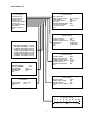
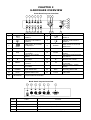
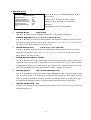
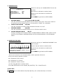
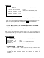
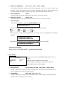
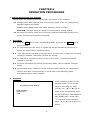
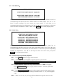
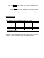
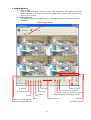
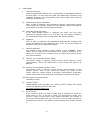
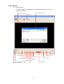
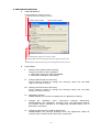
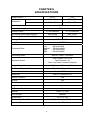
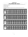
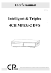
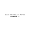
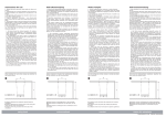
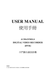
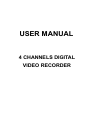
USER MANUAL
4 CHANNELS DIGITAL
VIDEO RECORDER
INSTRUCTION MANUAL
To obtain the best performance and ensure device function correctly, please read this instruction manual
carefully and completely.
FCC Compliance
USER-INSTALLER CAUTION: YOUR AUTHORITY TO OPERATE THIS FCC VERIFIED EQUIPMENT
COULD BE VOIDED IF YOU MAKE CHANGES OR MODIFICATIONS NOT EXPRESSLY APPROVED
BY THE PARTY RESPONSIBLE FOR COMPLIANCE TO PART 15 OF THE FCC RULES.
NOTE: THIS EQUIPMENT HAS BEEN TESTED AND FOUND TO COMPLY WITH THE LIMITS FOR A
CLASS A DIGITAL DEVICE, PURSUANT TO PART 15 OF THE FCC RULES. THESE LIMITS ARE
DESIGNED TO PROVIDE REASONABLE PROTECTION AGAINST HARMFUL INTERFERENCE WHEN
THE EQUIPMENT IS OPERATED IN A COMMERCIAL ENVIRONMENT.
THIS EQUIPMENT
GENERATES, USES, AND CAN RADIATE RADIO FREQUENCY ENERGY AND IF NOT INSTALLED
AND USED IN ACCORDANCE WITH THE INSTRUCTION MANUAL, MAY CAUSE HARMFUL
INTERFERENCE TO RADIO COMMUNICATIONS.
OPERATION OF THIS EQUIPMENT IN A RESIDENTIAL AREA IS LIKELY TO CAUSE HARMFUL
INTERFERENCE IN WHICH CASE THE USER WILL BE REQUIRED TO CORRECT THE
INTERFERENCE AT HIS OWN EXPENSE.
THIS CLASS A DIGITAL APPARATUS MEETS ALL REQUIREMENTS OF THE CANADIAN
INTERFERENCE-CAUSING EQUIPMENT REGULATIONS.
WARNINGS, CAUTIONS & COPYRIGHT
WARINGS
TO REDUCE THE RISK OF FIRE OR ELECTRIC SHOCK, DO NOT EXPOSE THIS PRODUCT TO RAIN
OR MISTURE.
DO NOT INSERT ANY METALLIC OBJECT THROUGH VENTILATION GRILLS.
CAUTION
CAUTION
RISK OF ELECTRIC SHOCK
DO NOT OPEN
CAUTION: TO REDUCE THE RISK OF ELECTRIC SHOCK.
DO NOT REMOVE COVER (OR BACK).
NO USER-SERVICEABLE PARTS INSIDE.
REFER SERVICING TO QUALIFIED SERVICE
Explanation of Graphical Symbols
The lightning flash with arrowhead symbol, within an equilateral triangle, is intended to
alert the user to the presence of insinuated "dangerous voltage" within the products
enclosure that may be of sufficient magnitude to constitute a risk of electric shock to
persons.
The exclamation point within an equilateral rhombus is intended to alert the user to the
presence of important operating and maintenance (servicing) instruction in the literature
accompanying the product.
USERS OF THE SYSTEM ARE RESPONSIBLE FOR CHECKING AND COMPLYING WITH ALL
FEDERAL, STATE, AND LOCAL LAWS AND STATUTES COIPCERNING THE MONITORING AND
RECORDING OF VIDEO AND AUDIO SIGNALS. ULTRAK SHALL NOT BE HELD RESPONSIBLE
FOR THE USE OF THIS SYSTEM IN VIOLATION OF CURRENT LAWS AND STATUTES.
COPYRIGHT
THE TRADEMARKS MENTIONED IN THE MANUAL ARE LEGALLY REGISTERED TO THEIR
RESPECTIVE COMPANIES.
2
TABLE OF CONTENTS
CHAPTER1 INTRODUCTION --------------------------------------------------------
5
CHAPTER2 HARDWARE OVERVIEW --------------------------------------------
6
CHAPTER3 SETUP PROCEDURES -----------------------------------------------
7
1. MAIN MENU SETUP ----------------------------------------------------------
7
2. SYSTEM SETUP ---------------------------------------------------------------
8
3. CAMERA SETUP --------------------------------------------------------------
9
4. RECORD SETUP ---------------------------------------------------------------
10
5. ALARM SETUP -----------------------------------------------------------------
11
6. SCHEDULES RECORD ------------------------------------------------------
11
7. EVENT LIST ---------------------------------------------------------------------
12
8. HDD MANAGEMENT ---------------------------------------------------------
12
9. VGA SETUP ---------------------------------------------------------------------
13
10. LOAD DEFAULT -------------------------------------------------------------
14
11. EXIT ------------------------------------------------------------------------------
14
CHAPTER4 OPERATION PROCEDURES ---------------------------------------
15
1. GETTING STARTED WITH YOUR MACHINE -------------------------
15
2. RECORDING --------------------------------------------------------------------
15
3. PLAYBACK ----------------------------------------------------------------------
15
4. HARD DISK RECOMMEND -------------------------------------------------
17
5. VGA OUTPUT -------------------------------------------------------------------
17
CHAPTER5 PLAYBAACK FROM USB -------------------------------------------
18
1. INTRODUCTION & SYSTEM REQUIREMENT ------------------------
18
2. VIEW & BACKUP --------------------------------------------------------------
19
3. MYS PLAYER -------------------------------------------------------------------
21
4. APPLICATION SETTING ----------------------------------------------------
23
CHAPTER6 SPECIFICATIONS ------------------------------------------------------
24
CHAPTER7 RECORDING TIME LENGTH ---------------------------------------
25
CHAPTER8 HARD DRIVE INSTALLATION PROCEDURES ---------------
26
V1.01 2007/Jan/09
3
SETUP MENU List
SETUP MENU
SYSTEM SETUP
SYSTEM SETUP
CAMERA SETUP
RECORD SETUP
ALARM SETUP
SCHEDULE RECORD
EVENT LIST
HDD MANAGEMENT
VGA SETUP
DEAFULT SETUP
EXIT
SET TIME/DATE
TIME DISPLAY MODE
TIME DISPLAY
LANGUAGE SELECT
KEY LOCK
MENU SETUP PROTECTION
CHANGE PASSWORD
SYSTEM SELECT
EXIT
2007/JAN/01
ON
ENGLISH
OFF
OFF
NTSC
CAMERA SETUP
CAMERA SELECT
CAMERA RECORD
MOTION SENTSITIVITY
BRIGHTNESS
CONTRAST
HUE
EXIT
EVENT LIST
START TIME: 2007/JAN/01 10:07:00
END TIME: 2005/JAN/05 12:07:30
> 01 RECORD 2007/JAN/05 12:07:00
02 MOT CH1 2007/JAN/05 12:06:00
03 MOT CH2 2007/JAN/04 12:05:00
04 MOT CH3 2007/JAN/04 10:04:00
05 MOT CH1 2007/JAN/02 12:03:00
06 RECORD 2007/JAN/02 22:02:00
07 POWER 2007/JAN/01 10:07:00
RECORD SETUP
RECORD MODE
NORMAL RECORD FPS
ALARM RECORD FPS
ALARM RECORD DWELL
RECORD QUALITY
MOTION MIGRATION
EXIT
HDD MANAGEMENT
OVERWRITE ENABLE
HDD FULL WARNING
HDD CAPACITY
HDD LEFT RATIO
HDD FORMAT
EXIT
CAM1
ON
1[MIN]
STANDARD
STANDARD
STANDARD
YES
10%
MUX
30P
30P
10SEC
HIGH
ON
76GB
73GB 97%
N/A
ALARM SETUP
VGA SETUP
RESOLUTION
FREQUENCY
EXIT
BUZZER DWELL
VIDEO LOSS ALARM
MOTION ALARM
ALARM DISPLAY MODE
EXIT
1024×768
60Hz
5SEC
ON
OFF
OFF
SCHEDULE SETUP
0
4
3
6
9
12
15
18
21
24
CHAPTER 1
INTRODUCTION
This product is 4 cameras input appliance with multiple function which will bring you following
features:
z
z
z
z
z
z
z
z
z
z
z
z
z
z
z
z
z
z
z
z
z
z
z
z
Device can be performed as VHS system with live display, play back and video recording.
Device operates in hardware base with no OS (operating system) necessary for more reliability
and stability.
Digitize data storage with M-JPEG compression technology will give you organized video
data management without using mess huge traditional video tape.
Support various type of camera with real, live mode display.
Multi-speed recording selection on normal recording mode or alarm recording mode, the
highest speed of recording is 30/25 (NTSC/PAL) fields on both mode.
Contrast, hue and brightness are adjustable for each camera individually.
Support 1 hard disk (HDD) from 40GB to 500GB compatible & status indicator on screen.
Selectable recording qualities (best/high/medium/low).
Recording can operate manually or gets activated automatically when motion is triggered.
Motion detection function available, user can easily adjust sensitive of motion detection.
Playback record can be searched by time or by event list.
Play back mode could not be easier then ever for you to review the video that gets recorded on
reverse (×16) and fast forwarding (×4, ×8, and ×16).
Play back mode with pause (field by field) for forward.
Easy operation, setting can be easily modified OSD (on screen display) menu.
Device will overwrite data and notice operator on monitor when the HDD is going full.
HDD capacity status can be show on the screen for better storage management.
System will restore the previous setting and continue camera activity after restart.
Provide optional VGA output function.
Support PC Link backup via USB connector.
Date type selectable.
NTSC/PAL switching by OSD menu.
Advanced buzzer control.
Force recording under schedule recording in no record mode.
Password & key lock protect even power lose.
5
CHAPTER 2
HARDWARE OVERVIEW
Front Panel Layout Overview
1
2
3
4
5
16 13 17
6
19
20
POWER
REC
Rec
Rew
Search
Stop
1
2
ENTER
Pause
3
F.Fwd
Search
PLAY
Play
MENU
4
22
QUAD
USB
7
Part
Label
1
3
5
8
9
10
11
14 15
12
DVR Function
DVR Function
2
Channel 2 Full screen &
number 2.
4
Channel 4 Full screen &
number 4.
1
3
Channel 3 Full screen &
number 3.
4
Quad screen: All cameras
are displayed.
6
ENTER
Recording button.
8
Rew Search
10
Pause
Rec
9
Stop
11
F.Fwd Search
13
▲
15
MENU
17
►
19
POWER
21
PLAY
23
IR Receiver
23
Label
2
7
PC
18
Part
Channel 1 Full screen &
number 1.
Quad
21
H.D.D
Press Stop to stop playback
or recording.
From ×4, x8, ×16 fast
forward.
Move upward or increase
the number.
Press MENU to go into or
exit menu.
Move rightward or increase
the number.
12
Play
14
▼
16
◄
Power status LED.
20
REC
Playback status LED.
22
H.D.D
USB
18
PC
Make choose or move into
MENU item.
×16 fast reward.
Pause & Picture by Picture
forward.
Play button & get into quick
time search.
Move downward or
decrease the number.
Move leftward or decrease
the number
USB connector Image
Backup
Recording status LED.
H.D.D LED
Accept IR Remote Controller
Back Panel Layout Overview
1
2
3
4
5
CAM1
CAM2
CAM3
CAM4
6
7
MONITOR OUT
VGA OUT
DC 12V
CAMERA IN
Part
Label
Function
1
Power connector
DC12V Power Adaptor in.
2-5
CAM1 2
Camera 1 2 3
6
MONITOR OUT
Composite video output with BNC connector.
7
VGA OUT
Connect to CRT or LCD monitor. (Option)
6
3 4
4 video input with BNC connector.
CHAPTER 3
SETUP PROCEDURES
0. LIVE VIEWING
Å---- STATUS BAR
REC 30P 2007/JAN/01 10:20:30 MON
MOT [CAM1]O O[CAM2]
[CAM3]O O[CAM4]
231GB/239GB 97% [FULL REC] MUX
STATUS BAR
Å---- INFORMATION BAR
Press ▲ button move from top or downgrade a line, and how many
recording FPS will show on the left upper corner.
INFORMATION BAR
Press ▼ button move from bottom or upgrade a line, by ◄ or ►
button to change information between HARD DISK STSTUS, RECORDING MODE and
AUDIO RECORDING STATUS.
While MENU mode without press any key would go back to live viewing mode
after 2 minutes. And during live viewing for 5 seconds would go back to
recording mode automatically, if full time or alarm record set before.
1. MAIN SETUP MENU
SETUP MENU
SYSTEM SETUP
CAMERA SETUP
RECORD SETUP
ALARM SETUP
SCHEDULE RECORD
EVENT LIST
HDD MANAGEMENT
VGA SETUP
DEAFULT SETUP
EXIT
Press the MENU button to go into the main
menu.
Use the ▲ or ▼ button to select items.
Press the ◄ or ► button to confirm the selection.
Press MENU to escape to exit the set up mode.
6. EVENT LIST
1. SYSTEM SETUP
Recording event list
System set up.
7. HDD MANAGEMENT
2. CAMERA SETUP
Hard disk management
Camera set up.
8. VGA SETUP
3. RECORD SETUP
VGA display set up.
Recording set up.
9. DEAFULT SETUP
4. ALARM SETUP
Return to factory setting
Alarm set up.
10. EXIT
5. SCHEDULE RECORD
Escape from the setup menu
Schedule Recording set up.
7
2. SYSTEM SETUP
SYSTEM SETUP
SET TIME/DATE
TIME DISPLAY MODE
TIME DISPLAY
LANGUAGE SELECT
KEY LOCK
MENU SETUP PROTECTION
CHANGE PASSWORD
SYSTEM SELECT
EXIT
a.
Press ▲ or ▼ key on "SYSTEM SETUP" & ◄ or ►
2007/JAN/01
ON
ENGLISH
OFF
OFF
to enter:
NTSC
Press MENU back to SETUP MENU.
Use the ▲ or ▼ button to select items.
Press the ◄ or ► button to confirm the selection.
SET TIME/DATE
Use W or X button to move, ▲ or ▼ button to set up date & time, by MENU key back
to menu.
b. TIME DISPLAY MODE
Use W or X button to change YY/MM/DD, MM/DD/YY or DD/MM/YY.
c. TIME DISPLAY
ON/OFF
Use W or X button to change ON or OFF.
d. LANGUAGE SELECT
ENGLISH
Use W or X button to change language.
e. KEY LOCK
ON/OFF
Use W or X button to change ON or OFF.
f.
MENU SETUP PROTECT
ON/OFF
Use W or X button to change ON or OFF.
g. CHANGE PASSWORD
Key in password with following sequence CURREBT PASSWORD -> NEW PASSWORD ->
CONFIRM PASSWORD. Initial number is 1111. Use the view control button on the front
panel to input the number.
h. SYSTEM SELECT
is "1" ,
is "2" ,
NTSC/PAL
Use W or X button to change NTSC or PAL video system.
8
is "3" ,
is "4"
3. CAMERA SETUP
Press ▲ or ▼ key on "CAMERA SETUP" & ◄ or
CAMERA SETUP
CAMERA SELECT
CAMERA RECORD
MOTION SENTSITIVITY
BRIGHTNESS
CONTRAST
HUE
EXIT
a.
CAMERA SELECT
CAM1
ON
1[MIN]
STANDARD
STANDARD
STANDARD
► to enter:
Use the ▲ or ▼ button to select items.
Press the ◄ or ► button to confirm the
selection.
Press MENU back to SETUP MENU.
CAM1/CAM2/CAM3/CAM4
Use ◄ or ► button to select the camera from CH1 – CH4 to be adjusted.
b. CAMERA RECORD
ON/OFF
Use ◄ or ► button to select recording function ON or OFF.
c.
MOTION SENTSITIVITY OFF / 1[MIN] / 2 / 3 / 4 / 5[MAX]
Use ◄ or ► button to adjust the sensitivity of the selected camera. From 0 (off) to 5
(MAX).
d. BRIGHTNESS
1 / 2 / 3 / 4 /STANDARD/ 6 / 7 / 8 / 9 /10
Use ◄ or ► button to adjust the brightness of the selected camera. Initial number is 5
(STANDARD).
e.
CONTRAST
1 / 2 / 3 / 4 /STANDARD/ 6 / 7 / 8 / 9 /10
Use ◄ or ► button to adjust the contrast of the selected camera. Initial number is 5
(STANDARD).
f.
HUE
1 / 2 / 3 / 4 /STANDARD/ 6 / 7 / 8 / 9 /10
Use ◄ or ► button to adjust the hue of the selected camera. Initial number is 5
(STANDARD).
9
4. RECORD SETUP
Press ▲ or ▼ key on "RECORD SETUP" & ◄ or
RECORD SETUP
RECORD MODE
NORMAL RECORD FPS
ALARM RECORD FPS
ALARM RECORD DWELL
RECORD QUALITY
MOTION MIGRATION
EXIT
a.
► to enter:
MUX
30P
30P
10SEC
HIGH
ON
RECORD MODE
Use the ▲ or ▼ button to select items.
Press the ◄ or ► button to confirm the
selection.
Press MENU back to SETUP MENU.
MUX/QUAD
Use ◄ or ► button to select MUX (multiplexer) or OD (QUAD) recording.
NORMAL RECORD FPS 1/2/3/4/5/7/10/15 & 30P
Use ◄ or ► button to select recording speed. 15P means 15 fields per second, 30P is
the highest speed, and 1P is the lowest. There are 1 / 2 / 3 / 4 / 5 / 7 / 10 / 15 & 30
you can choose, NTSC default 15P, PAL at 12P.
b.
ALARM RECORD FPS
1/2/3/4/5/7/10/15 & 30P
Use ◄ or ► button to select alarm recording speed when external alarm or motion
detection is triggered. There are 1 / 2 / 3 / 4 / 5 / 7 / 10 / 15 & 30 you can choose,
NTSC default 30P, PAL at 25P.
c.
ALARM RECORD DWELL 1~30SEC
Use ◄ or ► button to set the dwell time for alarm recording when motion detection is
triggered. There are a total of 30 speeds you can choose from 1 to 30. When Motion
is triggered and within the dwell period: the screen will be switched into quad mode.
The corresponding camera will be marked ID "MOT", default 10 seconds..
d.
RECORD QUALIT
BEST/HIGH/MEDIUM/LOW
Use ◄ or ► button to select the BEST, HIGH, MEDIUM or LOW recording quality that
can be chosen from. The amount of storage will be consumed with higher quality.
Thus, this setting should be carefully chosen for hard disk volume. A table at cheap 6
for relationship between quality, recording speed and hard disks for reference.
e.
MOTION MIGRATION
ON
Use ◄ or ► button to select add detected motion into event list or not, and the
default setting is on.
10
5. ALARM SETUP
Press ▲ or ▼ key on "ALARM SETUP" & ◄ or ►
ALARM SETUP
BUZZER DWELL
VIDEO LOSS ALARM
MOTION ALARM
ALARM DISPLAY MODE
EXIT
to enter:
5SEC
ON
OFF
OFF
Use the ▲ or ▼ button to select items.
Press the ◄ or ► button to confirm the
selection.
Press MENU to go back to SETUP MENU.
a.
BUZZER DWELL
1/2/3 to 30 SEC & CONT
Use ◄ or ► button to set the dwell time for buzzer issue occur. There are a total of
31 periods you can choose from 1 to 30 seconds or "CONT" for constantly.
b.
VIDEO LOSS ALARM
ON/OFF
Use ◄ or ► button to select video loss alarm function on or off.
c.
MOTION ALARM
ON/OFF
Use ◄ or ► button to switch function on or off when motion occur.
d.
ALARM DISPLAY MODE
ON/FF
During recording & full channel mode, if ALARM DISPLAY MODE is ON, system would
switch to the ALARM or MOTION channel and the period depend on ALARM RECORD
DWELL.
6. SCHEDULE RECORD
Press ▲ or ▼ key on "SCHEDULE RECORD" & ◄
SCHEDULE SETUP
0
3
6
9
12
15
18
or ► to enter:
21
24
Use the ◄ or ► button to select items.
Press the ▲ or ▼ button to confirm the
[RIGHT,LEFT] TO MOVE [MENU TO EXIT]
[UP,DOWN] TO SELECT
selection.
Press MENU to go back to SETUP MENU.
There are 24 circles in the schedule table, which represent 24 hours.
Every circle has 3 options to select:
O : represents "fully record"
X : represents "no record"
A : represents "alarm record"
Use the ◄ or ►button to select hours.
Press ▲ or ▼ button to select the O / X / A (Fully / No / Alarm Record).
QUICK KEY:
Play
Key to switch between O / X / A (Fully / No / Alarm Record) in all hours.
11
7. EVENT LIST
EVENT LIST
Press ▲ or ▼ key on "EVENT LIST" & ◄ or ►
START TIME: 2007/JAN/01 12:07:06
END TIME: 2007/JAN/05 12:07:30
>01 RECORD
02 MOT CH1
03 MOT CH2
04 POWER
05 RECORD
06 RECORD
07 POWER
2007/JAN/05
2007/JAN/05
2007/JAN/04
2007/JAN/03
2007/JAN/03
2007/JAN/02
2007/JAN/01
10:07:06
12:06:18
12:05:22
22:04:45
12:03:00
05:02:34
12:07:06
to enter:
Use the ◄ or ► button to select items.
Press the ▲ or ▼ button to confirm the
selection.
Press MENU back to SETUP MENU.
Use "▲ or ▼" key to select event which needs to be played location of " > " symbol will
move up and down for indicating current event which been selected.
Press "◄ or ►" key to select events storage from master hard drive or slave hard drive.
When once selection has been made and than press ►PLAY key to start playback.
There are totally 3 different type's event will be recorded:
1. RECORD Event starts recording by press "REC" key.
2. POWER When power off or loss, system would add this issue, and "POWER
ERROR DETECTED" would show on screen while boot.
3. MOT CH1 When motion detection was triggered, event up with alarm number.
Record setup "MOTION EVENT MIGRATION" must at ON.
In the period of alarm record triggered constantly that the a single EVENT LIST item will be
extend while lapsed, thus ENET LIST would show the first triggered channel number on the list
and the recording seconds will be extended .
8. HDD MANAGEMENT
HDD MANAGEMENT
OVERWRITE ENABLE
YES
HDD FULL WARNING
10%
HDD CAPACITY 76GB
HDD LEFT RATIO
73GB 97%
HDD FORMAT N/A
EXIT
Press ▲ or ▼ key on "NETWORK SETUP" & ◄ or ► to
enter:
Use the ◄ or ► button to select items.
Press the ▲ or ▼ button to confirm the selection.
Press MENU back to SETUP MENU.
a.
OVERWRITE MODE
YES (YES/NO)
Use "◄ or ►" button to enable or disable overwriting when HDD is full. When HDD
overwrite is enabled, the oldest partition on HDD will automatically be reused, and the
oldest images will be overwritten the current images. When overwrite mode is disabled,
the HDD Full Warning percentage selection will be appeared and need to be
configured.
12
b. HDD FULL WARNING
10% (5% / 10% / 15% / 20%)
Use "◄ or ►" button to select one of the four settings (5% / 10% / 15% / 20%). The
default is 10%. The buzzer will turn on when free space left in the HDD go below the
set value and alarm again when the total free space left going down each 5%.
c.
HDD CAPACITY
76GB
The HDD capacity will be indicated on the screen, it can't be revised.
d. HDD LEFT RATIO
73GB 97%
The HDD left ratio sign will be indicated on the screen, it can't be revised.
e.
HDD FORMAT
Use "◄ or ►" button to enter the HDD FORMAT menu.
PASSWORD INPUT : _ _ _ _
Use the view control button on the front panel to input the number.
is "1" ,
is "2" ,
is "3" ,
is "4"
When you key in the correct password, the screen will be displayed the following
message:
PASSWORD CORRECT!
HARD DISK FORMATTED
Otherwise, the following error message will be displayed on the screen:
PASSWORD INCORRECT!
CHANGE PASSWORD:
Please refer to “SYSTEM SETUP” Æ CHANGE PASSWORD.
9. VGA SETUP
VGA SETUP
RESOLUTION
FREQUENCY
EXIT
1024×768
70Hz
Press ▲ or ▼ key on "NETWORK SETUP" & ◄ or ► to
enter:
Use the ◄ or ► button to select items.
Press the ▲ or ▼ button to confirm the selection.
Press MENU back to SETUP MENU.
a.
RESOLUTION
1024×768 (640×480 / 800×600 / 1280×1024)
Use ◄ or ► button to select 4 kinds of resolutions. This setting on VGA setup has to
be the same as the setting on the monitor.
b. FREQUENCY
70Hz (56 / 60 / 70 / 75)
Use ◄ or ► button to select 4 kinds of frequencies. This setting on VGA setup has to
the same as the setting on the monitor.
13
10. LOAD DEFAULT
ARE YOU SURE
> NO
YES
Press ▲ or ▼ key on "DEAFULT SETUP" & ◄ or ► to
enter:
Use the ◄ or ► button to select items.
Press the ▲ or ▼ button to confirm the selection.
Press MENU back to SETUP MENU.
a.
NO
Do not load default
b. YES
Use W or X button to restore the default setting.
11. EXIT
Exit from the SETUP MENU.
14
CHAPTER 4
OPERATION PROCEDURES
1 Getting Started with your machine
Please assure the following instructions before you switch on the machine:
1.1 Voltage check: Before power cable is connected, please check the voltage of this
appliance against the supply.
Adapter input voltage range 100~240V, frequency range 47-63Hz.
CAUTION - Damage would be caused if incorrect power voltage applied.
1.2 Hard Disk connection: Make sure the 40-Pin Hard Disk Data cable and the 4-Pin
power connectors are properly connected.
2
Recording
2.1
Press the
REC key to enter the Recording Mode. And press the STOP key to
stop recording.
2.2
On information bar the "MUX" or "QUAD sign will be indicated on the screen, it
means you select MUX or QUAD recording.
2.3
"15P" sign will be indicated in top right corner on the screen, it mean the recording
speed you selected. 15P means 15 fields per second.
2.4
O" sign will be indicated in center corner on the screen, it means the marked
channel is recorded.
2.5
For more information on Setting up Recording Mode, refer to Chapter 3 Record
Setup
2.6
In Recording Mode, if there is a power failure or power lost for any reasons that
cause a shut down of this machine, it will be back to the Recording Mode
automatically when power restored.
3
Playback
Press the ►PLAY button to into
playback mode, There are two
PLAYBACK TYPE SELECT
ways for searching for video
records, use
>TIME SEARCH
EVENT LIST
EXIT
" " or " " key to
select a way for searching, there
are two selections "TIME SEARCH"
and "EVENT LIST". Arrow mark
">" indicates current selection,
press "◄" or "►" key to start the
search.
15
3.1
Time Search
TIME SEARCH
START TIME: 2007/JAN/05 08:40:34
^
START TIME 2007/JAN/01 08:12:03
END TIME 2007/JAN/05 12:10:55
When entered "TIME SEARCH" mode, screen will indicates the earliest record on
corresponding hard drive with title "START TIME" and "END TIME". Use "◄" or "►"
keys to setup condition for time search, an arrow mark "^" will show up on
corresponding location for adjustment. Use "▲ "or "▼ "keys to increases or decrease
value for search condition on time or date. Press ►PLAY key to start playing back.
3.2
Event List
EVENT LIST
START TIME: 2007/JAN/01 12:07:00
END TIME: 2007/JAN/05 10:47:30
> 01 RECORD 2007/JAN/05 09:07:00
02 MOT CH1 2007/JAN/04 12:06:00
03 MOT CH2 2007/JAN/04 10:05:00
04 RECORD 2007/JAN/02 22:04:00
05 POWER 2007/JAN/01 12:07:00
When entered "EVENT LIST" mode. Screen will indicates the event list on
corresponding hard drive with the event type, start date & time. Use "▲"or "▼" keys
to setup condition for time search, an arrow mark ">" will show up on corresponding
location for adjustment. Use "▲ "or "▼"keys to select the event item, and press
►PLAY key to start playing back.
3.3
Several ways to perform playback:
3.3.1
Press ►PLAY button to play video forward.
3.3.2
"PLAY" sign will be indicated in top left corner on the screen.
"MUX or QUAD" sign will be indicated in top right corner on the screen,
it means the recording mode you selected.
3.3.3
When playback reaches the vary end of record and "END"will appear.
Press
Rew Search button to play video reverse at 16 times speed fast
rewind mode.
3.3.4
Press
F.Fwd Search button to play video forward at high speed. Press
the button again speed will be change circulative from ×4, ×8, to the highest
×16.
3.3.5
"REW" or "FF* 4 / 8 / 16" sign will be indicated in top left corner on the
16
screen.
3.3.6
Press
Pause button to pause (field by field) for forward. This function
can be used in full screen and quad mode.
3.3.7
"PAUSE" sign will be indicated in top left corner on the screen.
Press the STOP button to leave playback mode and resume to Live Mode.
Attention If you choose QUAD in recording mode than it can't playback in
full single channel screen.
4 Hard disk recommend
Hard disk should be connected, the capacity of hard disk from 40GB to 500GB.
When you restart the power of this appliance after install or replace new hard disk it will
format automatically, we tested the following model for your reference:
Brand
Model
Capacity
Speed (rpm)
Hitachi
HDS725050KLAT80
500GB
7200 rpm
Seagate
ST380011A
80GB
7200 rpm
Seagate
ST3120023A
120GB
7200 rpm
Seagate
ST3160023A
160GB
7200 rpm
Seagate
ST3400832A
400GB
7200 rpm
Maxtor
6Y120L0
120GB
7200 rpm
Maxtor
6Y080L0
80GB
7200 rpm
Maxtor
6Y160P0
160GB
7200 rpm
Maxtor
7Y250P0-A
250GB
7200 rpm
We DO NOT suggest Samsung \ Western Digital \ Maxtor DiamondMax 10 series hard drive
base on technical examination.
5 VGA Output
VGA output is optional, please ensure that you have proper DVR model for VGA out put
installation. By D-SUB connecter to CRT or LCD monitor at 1024*768 70Hz.
17
CHAPTER 5
PLAYBACK FROM USB
1. INTRODUCTION & SYSTEM REQUIREMENT
A.
INTRODUCTION
Form YAViewer4 software will show the stream image stored in the HDD which was
previously formatted and recorded from DVR via USB cable.
When DVR connected to PC, DVR would stop to recording and ”USB ►►► PC”
will show on the DVR screen for HDD data transmission, after unplug the USB
connector DVR would boot up automatically.
The YAViewer4 will automatically detect the HDD and show the recorded stream.
You can also save the current screen to a BMP file, and save the current stream to
a stream file [the file extension for the stream file is “MYS”].
The YAViewer4 consists of two functional modules:
View & Backup
Shows stream stored in the HDD directly.
MYS File Player
Plays captured stream file.
B.
SYSTEM REQUIREMENT
System Recommendation
Microsoft Windows 2000 or Later (XP, 2003).
CPU 1.0 GHz or Higher.
RAM 256 MByte or greater.
DirectX 7.0 or later.
C.
INSTALLATION
Hardware Installation
With the USB cable link DVR and USB port on PC.
DVR would switch into “USB to PC” mode, after disconnection system would reboot
automatically.
if your operation system
require initialing the new detect DVR hard disk,
please cancel this initial action!! , all of data will erase if
PC would detect new HDD added,
been initialed.
As stated above, the application shows stream which is stored in HDD from DVR.
Before installing and executing the application, make sure that you connected HDD
to the IDE cable of your PC directly, or via USB HDD adaptor.
Software Installation
Make sure that the OS of your PC is Windows 2000 or above. Otherwise, the
application will not operate properly.
The application is just one execution file. Please copy from DVR CD disk to any
directory you want.
18
2. VIEW & BACKUP
A. EXECUTION
Please double click the execution file. The application first detects physical
HDDs installed at your PC and search for HDD among them. This process may
take up to 1 minute.
B. USER INTERFACE
The default page of the application is DVR HDD PC Viewer. The user interface
as below:
HDD Select Button
F. Rewind
Direct Access
Volume Control
Play Captured Stream Button
F. Forward
Rewind by Frame
R. Play
Slider Bar Zooming Button
Valid Stream Region Indicator
Forward by
Capture Current Stream Button (MYS)
Frame
Play
Pause
Capture Current Stream Button (BMP)
Channel Selection
Slider Bar
Stream Time Display
19
C.
FUNCTIONS
I.
HDD Select Button
Once the application detects one or more HDDs, it automatically selects
the first HDD. You can select any HDD [the HDDs with YAViewer4_Eng
marked]. However, you cannot select the normal HDD, which may be
Windows-formatted one.
II.
Valid Stream Region Indication
Once a HDD is selected, the application detects valid stream region
where valid video stream resides. The valid stream region is marked as
green within the Valid Stream Region Indicator.
III. Slider Bar Zooming Button
If the Valid Stream Region is relatively too small, you may have
difficulty to navigate within it. In this case, we can enlarge (magnify)
the Valid Stream Region by clicking Slider Bar Zooming Button.
IV. Playback
Once a HDD is selected, the application automatically displays first
screen recorded at the very beginning of it. Then, we can see stream at
anywhere within the valid stream reason.
V.
Channel Selection
The default screen display channel setting is ALL CHANNEL, which
shows all four channel (if the stream has 4 channel streams) at the
same time. If want to see a channel only or enlarge one channel, press
any channel button.
VI. Capture Current Stream Button (BMP)
For capture image, or backup, current screen, press Capture Current
Screen button. Then it will capture the current screen and saves it as
BMP file.
VII. Capture Current Stream Button (MYS)
For capture video, or backup, current stream, press Capture Current
Stream button. Then it will record the stream you want. It will
create .MYS file, whose format is Vineyard Technologies’ proprietary
stream file format. We can play the recorded file using MYS file player.
VIII. Play Capture Stream Button
MYS Player mode.
IX. Volume Control
Enable/disable audio sounding by clicking “MUTE” button and adjust
volume by adjusting Volume slider bar.
For audio optional model only.
X.
Direct Access
If the stream stored in a HDD is quite long or difficulty to reach the
exact scene to see. If we find a scene you would like to show your
friend or report to polis officer later, please remember the number in
the Direct Access Input edit box, so that we can go there directly by
entering the number in the edit box and pressing “GO” button besides
it.
20
3. MYS PLAYER
A.
User Interface
The default page of the application is DVR HDD YAViewer4. The user
interface as below:
MYS File Select Dialog
MYS File Info Display
MYS Player
File Open Button
F. Forward
F. Rewind
Forward by
Rewind by Frame
R. Play
MYS File Info. Display Button
Positioning Slider Bar
Volume Control
Capture Current
PlayFrame
Channel Selection
Pause
21
B.
FUNCTIONS
I.
File Open
Open MYS file by clicking File Open Button.
II.
Playback
Once a HDD is selected, the application automatically displays first
screen recorded at the very beginning of it. Then, we can see stream at
anywhere within the valid stream reason.
III. Channel Selection
The default screen display channel setting is ALL CHANNEL, which
shows all four channel (if the stream has 4 channel streams) at the
same time. If want to see only one channel as full screen, press
channel button.
IV. Capture Current Stream Button (BMP)
For capture image, or backup, current screen, press Capture Current
Screen button. Then it will capture the current screen and saves it as
BMP file.
V.
Volume Control
Enable/disable audio sounding by clicking “MUTE” button and adjust
volume by adjusting Volume slider bar.
For audio optional model only.
VI. Position Slider Bar
Slide image position directly.
VII. MYS File Info. Display Button
Showing File Name, Video Mode, File Size, and Frame Count & Current
Position at upper left corner.
22
4. APPLICATION SETTING
A. USER INTERFACE
Change BMP File Saving Directory
Change MYS File Saving Directory
Default Video Mode
Default Video Mode
Enable/Disable Application Closing Confirm
Enable/Disable Notification Message when the application detects the
Enable/Disable Notification Message when the application detects invalid
B.
FUNCTIONS:
I.
Default Video Mode Related Setting
Choose the default video standard.
1. NTSC/PAL Setting for HDD PCVIEWER
2. NTSC/PAL Setting for MYS Player
II.
Change BMP File Saving Directory
Press “Change” Button to change the directory where the new BMP
capture file will be stored.
III. Change MYS File Saving Directory
Press “Change” button to change the directory where the new MYS
stream file will be stored.
IV. Application Closing
Enable/Disable the confirm message box for application closing.
V.
Change No Hardware Color Conversion Support Notification
Enable/Disable the notification message when the application detects
the graphic device installed is not supporting hardware-aided YUV to
RGB color conversion.
VI. Change Invalid Stream Loading Notification
Enable/Disable the warning message when the application [HDD PC
Viewer] loads invalid stream data from a hard disk.
23
CHAPTER 6
SPECIFICATIONS
NTSC
PAL
Display
720 × 480
720 × 576
Record
640 × 224
640 × 272
Image System
Resolution
Video Input
BNC × 4
Video Output
BNC × 1
Display Frame
4 × 30 fields/sec
4 × 25 fields/sec
Max 30 fps
Max 25 fps
Max 30 / 4 fps
Max 25 / 4 fps
Recording Frame Rate (QUAD)
Recording Frame Rate (MUX)
Storage Media
1 IDE Hard Disk
Image Format
M-JPEG
Compress Rate
Low
Medium
High
Best
8K bytes/field
10K bytes/field
15K bytes/field
20K bytes/field
Recording Mode
Manual / Alarm / Schedule
Playback Speed
Fast Forward ×4 ×8 ×16
Fast Reverse ×16
Frame by Frame Forward Playback
Image Adjustable
Brightness / Contrast / Hue
On Screen Display & Setup
Time/Date/Setup Menu
Password Control
One for HDD format
Event List
Max. 63 records/H.D.D
Motion Detection
Yes
Buzzer
Yes
Video loss
Yes
Key Lock
Yes
IR Remote Controller
Yes
Backup
USB ( PC Link)
VGA out put
Optional
Power Input
DC 12 V / 3A
Dimensions (W×H×D)
218 (W) × 44 (H) × 202 (D) mm
Operation Temperature
0 - 45
24
CHAPTER 7
RECORDING TIME LENGTH
Recording time length is related to recording speed and recording quality. Tables below are
offered for your reference.
Record Mode=MUX
Record Mode=QUAD
Recording length under quad mode will shorter than multiplex mode and PAL will shorter
than NTSC.
80GB H.D.D Record Mode=MUX
NTSC Field/Sec
30/FS 15/FS 10/FS
maximum 38 hr
high
Recording
Quality medium
low
NTSC Field/Sec
low
PAL Field/Sec
maximum
high
Recording
Quality medium
low
5/FS
4/FS
3/FS
2/FS
1/FS
76 hr
114 hr
160hr
228hr
285hr
380 hr 570 hr 1140hr
57 hr
114Hr
171hr
240hr
342hr
428hr
570 hr 855 hr 1710hr
71 hr
142hr
213hr
298hr
426hr
532hr
710 hr 1065hr 2130hr
100hr
200hr
300hr
420hr
600hr
750hr 1000hr 1500hr 3000hr
80GB H.D.D Record Mode=QUAD
30/FS 15/FS 10/FS 7/FS 5/FS 4/FS
maximum 19 hr
high
Recording
Quality medium
7/FS
3/FS
2/FS
1/FS
38 hr
57 hr
80 hr
114hr
142hr
190hr
285hr 570 hr
29 hr
57 Hr
87 hr
120hr
171hr
214hr
285hr
426hr
35 hr
70 hr
105 hr
148hr
213hr
266hr
350hr
532hr 1050hr
100 hr 150 hr
208hr
300hr
375hr
500hr
750hr 1500hr
50 hr
80GB H.D.D Record Mode=MUX
25/FS 12/FS
8/FS
6/FS
4/FS
870 hr
3/FS
2/FS
1/FS
35 hr
72 hr
110 hr
145 hr
218 hr
291 hr
437 hr
875 hr
46 hr
95 hr
144 hr
190 hr
287 hr
383 hr
575 hr
1150 hr
67 hr
139 hr
209 hr
278 hr
418 hr
558 hr
837 hr
1675 hr
98 hr
204 hr
306 hr
408 hr
612 hr
816 hr
1225hr
2450hr
80GB H.D.D Record Mode=QUAD
PAL Field/Sec
maximum
high
Recording
Quality medium
low
25/FS
12/FS
8/FS
6/FS
4/FS
3/FS
2/FS
1/FS
12 hr
25 hr
37 hr
50 hr
75 hr
100 hr
150 hr
300 hr
16 hr
33 hr
50 hr
66 hr
100 hr
133 hr
200 hr
400 hr
23 hr
48 hr
72 hr
95 hr
143 hr
191 hr
287 hr
575 hr
34 hr
70 hr
106 hr
141 hr
212 hr
283 hr
425 hr
850 hr
25
CHAPTER 8
HARD DRIVE INSTALLATION PROCEDURES
1. Loosen the screw on the cover of the DVR. There are total 8 screws as follows.
2. Install HDD (Master) and connect it with the power board and the main board as well
as follows.
3. Turn the bottom of the DVR up and make 4 screws on as follows. Screws are inside the
26
accessory kit.
4. After HDD installed and the power connected well, turn on the DVR. Then, OSD will
display HDD information. After confirmation, screw on the cover of the DVR.
Attentions
1.
2.
3.
4.
Hard drive master mode must be set correctly.
Make sure power cable is unplugged before hard drive installation starts.
IDE cable and power cable must be hooking up correctly.
HDD cool down is based on the DVR case, so please make sure the HDD is
installed well.
27