1
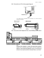
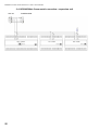
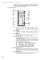
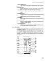
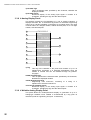
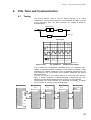
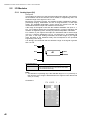
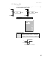
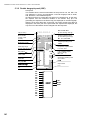
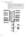
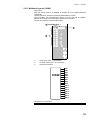
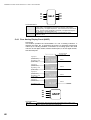
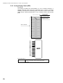
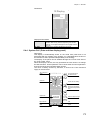
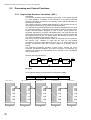
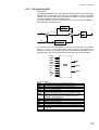
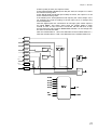
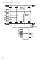
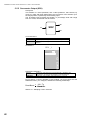
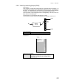
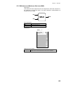
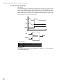
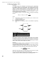
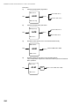
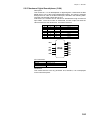
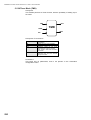
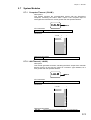
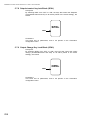
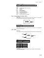
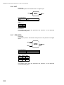
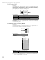
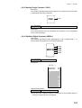
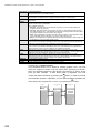
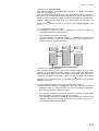
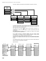
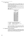
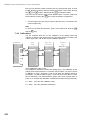
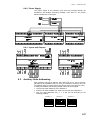
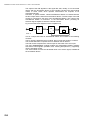
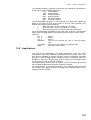
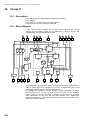
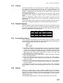
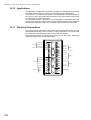
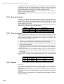
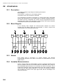
Installation and User manual of the AC10 - AC20 - AC30 controller
Once terminated this configuration step, the Tune procedure is launched, by
carrying on the following steps, that allow you to specify the loop to be tuned.
TAG-0000-0
l/h
LSP
Main
Menu
573
550
1200
Tune & Views
Par. & Comms
Prog & Test
Keyb. Perm.
Loc
Loc
HLD
R
Tuning
Tuning and
View
Choice
Tuning (Auto)
Tuning (Man)
PID Param.
F.Panel View
LCD Contrast
E
E
E
R
PID_LOOP 1
PID_LOOP 2
PID_LOOP 3
PID_LOOP 4
E
Eo R
E
AL1
R
AL2
R
R
MAN
W=5 min
0
OUT= 63
During the Tuning process, the message “Tune PID LOOP...” appears in the
tag field, at the top of the display panel of the loop under tuning.
It is possible to abort the Tuning procedure, anytime before the completion,
forcing the loop to Manual or returning back to the Main Menu display.
The controllers recognizes the abort of the Tuning, by displaying the
message “Tuning Aborted”. This message disappears after the user has
acknowledge it, by stroking any key.
You can select between two operating modes of the Tune algorithm,
according to the way the computed PID terms values are used: an AUTO
mode, that, at the end of the processing, writes the computed PID terms
values in the loop parameters directly, and a MAN (Manual) one, that
presents the values on the display, asking the user to confirm or cancel,
before writing them in the loop.
Tuning PID 1
l/h
LSP
573
550
1200
Tuning Completed
Loc
Old Values
Loc
P.B. = 12.85
Int.T. = 21
Der.T. = 4.20
New Values
E
HLD
P.B. = 17.13
Int.T. = 20
Der.T. = 4.00
AL1
Display panel at the
end of the Tuning
procedure (Man)
Enter Key : Accept
AL2
Other Key : Reject
MAN
W=5 min
0
OUT= 63
4.2
Gain Scheduling
Gain scheduling is based on the technique of changing the value of the 3
terms parameters of the PID algorithm, according to the value of a variable,
like the setpoint, the manipulated variable, the controlled variable and other
process signals. The main purpose of this functionality is to adjust
automatically the 3 terms parameters when dynamic changes occur in the
process to control, as, for instance, a load change. The gain scheduling is a
very effective control technique with superb results, but its diffusion has been
limited by the high skills and the considerable development efforts required to
implement it.
38