1
____________________
Information in this document is subject to change without notice.
© 1999 Dell Computer Corporation. All rights reserved.
Reproduction in any manner whatsoever without the written permission of Dell Computer Corporation is strictly forbidden.
Trademarks used in this text: Dell, the DELL logo, and Latitude are trademarks of Dell Computer Corporation; IBM is a registered trademark of
International Business Machines Corporation.
Other trademarks and trade names may be used in this document to refer to either the entities claiming the marks and names or their products.
Dell Computer Corporation disclaims any proprietary interest in trademarks and trade names other than its own.
August 1999
P/N 0813P Rev. A02
Recommended Tools. . . . . . . . . . . . . . . . . . . . . . . . . . . . . . . . . . . . . . . . . . . . 2
Preparing to Work Inside Your Computer . . . . . . . . . . . . . . . . . . . . . . . . . . . . 2
Screw Identification and Tightening . . . . . . . . . . . . . . . . . . . . . . . . . . . . . . . . 3
ZIF Connectors . . . . . . . . . . . . . . . . . . . . . . . . . . . . . . . . . . . . . . . . . . . . . . . . 4
Field-Replaceable Parts and Assemblies . . . . . . . . . . . . . . . . . . . . . . . . . . . . 5
Removing Field-Replaceable Parts and Assemblies . . . . . . . . . . . . . . . . . . . 12
Hard-Disk Drive Assembly . . . . . . . . . . . . . . . . . . . . . . . . . . . . . . . . . . . . 13
Memory Module Cover . . . . . . . . . . . . . . . . . . . . . . . . . . . . . . . . . . . . . . 14
Memory Modules . . . . . . . . . . . . . . . . . . . . . . . . . . . . . . . . . . . . . . . . . . 15
Keyboard Assembly . . . . . . . . . . . . . . . . . . . . . . . . . . . . . . . . . . . . . . . . . 16
Back Cover Assembly . . . . . . . . . . . . . . . . . . . . . . . . . . . . . . . . . . . . . . . 18
Palmrest Assembly . . . . . . . . . . . . . . . . . . . . . . . . . . . . . . . . . . . . . . . . . 19
Touch-Pad Interface Module . . . . . . . . . . . . . . . . . . . . . . . . . . . . . . . . . . 20
Power Button. . . . . . . . . . . . . . . . . . . . . . . . . . . . . . . . . . . . . . . . . . . . . . 21
Display Assembly . . . . . . . . . . . . . . . . . . . . . . . . . . . . . . . . . . . . . . . . . . 21
Display Assembly Bezel. . . . . . . . . . . . . . . . . . . . . . . . . . . . . . . . . . . . . . 23
Display Assembly Latch. . . . . . . . . . . . . . . . . . . . . . . . . . . . . . . . . . . . . . 23
LCD Panel . . . . . . . . . . . . . . . . . . . . . . . . . . . . . . . . . . . . . . . . . . . . . . . . 24
12.1-Inch LCD Displays . . . . . . . . . . . . . . . . . . . . . . . . . . . . . . . . . . . 24
13.3-Inch LCD Displays . . . . . . . . . . . . . . . . . . . . . . . . . . . . . . . . . . . 26
LCD Display Hinge . . . . . . . . . . . . . . . . . . . . . . . . . . . . . . . . . . . . . . . . . . 28
Display-Assembly Top Cover . . . . . . . . . . . . . . . . . . . . . . . . . . . . . . . . . . 28
Bottom Case Assembly . . . . . . . . . . . . . . . . . . . . . . . . . . . . . . . . . . . . . . 28
Modular Bay Devices (Diskette Drive, CD-ROM Drive, Battery, or
Travel Module) . . . . . . . . . . . . . . . . . . . . . . . . . . . . . . . . . . . . . . . . . . . . . 30
Audio Shield . . . . . . . . . . . . . . . . . . . . . . . . . . . . . . . . . . . . . . . . . . . . . . 30
Audio Board . . . . . . . . . . . . . . . . . . . . . . . . . . . . . . . . . . . . . . . . . . . . . . 31
Bottom Case Bracket. . . . . . . . . . . . . . . . . . . . . . . . . . . . . . . . . . . . . . . . 32
Module Latch Assemblies . . . . . . . . . . . . . . . . . . . . . . . . . . . . . . . . . . . . 33
Speakers . . . . . . . . . . . . . . . . . . . . . . . . . . . . . . . . . . . . . . . . . . . . . . . . . 34
System Board Assembly . . . . . . . . . . . . . . . . . . . . . . . . . . . . . . . . . . . . . 35
Exhaust Fan . . . . . . . . . . . . . . . . . . . . . . . . . . . . . . . . . . . . . . . . . . . . . . . 39
I/R Board . . . . . . . . . . . . . . . . . . . . . . . . . . . . . . . . . . . . . . . . . . . . . . . . . 40
Reserve Battery . . . . . . . . . . . . . . . . . . . . . . . . . . . . . . . . . . . . . . . . . . . 41
v
vi
Figure 1.
Figure 2.
Figure 3.
Figure 4.
Figure 5.
Figure 6.
Figure 7.
Figure 8.
Figure 9.
Figure 10.
Figure 11.
Figure 12.
Figure 13.
Figure 14.
Figure 15.
Figure 16.
Figure 17.
Figure 18.
Figure 19.
Figure 20.
Figure 21.
Figure 22.
Figure 23.
Figure 24.
Figure 25.
Figure 26.
Figure 27.
Figure 28.
Figure 29.
Figure 30.
Figure 31.
Computer Orientation . . . . . . . . . . . . . . . . . . . . . . . . . . . . . . . . 1
Main Battery Assembly Removal . . . . . . . . . . . . . . . . . . . . . . . 3
Screw Identification . . . . . . . . . . . . . . . . . . . . . . . . . . . . . . . . . 3
Disconnecting an Interface Cable . . . . . . . . . . . . . . . . . . . . . . . 4
Exploded View—Computer . . . . . . . . . . . . . . . . . . . . . . . . . . . 12
Hard-Disk Drive Assembly Removal . . . . . . . . . . . . . . . . . . . . 13
Memory Module Cover Removal . . . . . . . . . . . . . . . . . . . . . . 14
Memory Module Removal . . . . . . . . . . . . . . . . . . . . . . . . . . . 15
Keyboard Assembly Screw Removal . . . . . . . . . . . . . . . . . . . 16
Keyboard Assembly Removal . . . . . . . . . . . . . . . . . . . . . . . . . 17
Back Cover Assembly Removal . . . . . . . . . . . . . . . . . . . . . . . 18
Palmrest Assembly Removal . . . . . . . . . . . . . . . . . . . . . . . . . 19
Touch-Pad Interface Module Removal . . . . . . . . . . . . . . . . . . 20
Display Assembly Removal . . . . . . . . . . . . . . . . . . . . . . . . . . . 21
Display Assembly Bezel Removal
(12.1-Inch Display Shown). . . . . . . . . . . . . . . . . . . . . . . . . . . . 23
LCD Panel Removal (12.1-Inch Display) . . . . . . . . . . . . . . . . . 24
Cable Layout for the 12.1-Inch LCD Panel . . . . . . . . . . . . . . . 25
LCD Panel Removal (13.3-Inch Display) . . . . . . . . . . . . . . . . . 26
Two-Piece Cable Layout for the 13.3-Inch LCD Panel . . . . . . 27
Bottom Case Assembly . . . . . . . . . . . . . . . . . . . . . . . . . . . . . 29
Modular Bay Device Removal . . . . . . . . . . . . . . . . . . . . . . . . . 30
Audio Board Removal . . . . . . . . . . . . . . . . . . . . . . . . . . . . . . . 31
Bottom Case Bracket Removal . . . . . . . . . . . . . . . . . . . . . . . . 32
Module Latch Assemblies Removal . . . . . . . . . . . . . . . . . . . . 33
Left Slider . . . . . . . . . . . . . . . . . . . . . . . . . . . . . . . . . . . . . . . . 34
System Board Assembly Removal . . . . . . . . . . . . . . . . . . . . . 35
One- and Two-Slot Processor Hold-Down Clips . . . . . . . . . . . 37
Microprocessor Module . . . . . . . . . . . . . . . . . . . . . . . . . . . . . 38
Exhaust Fan Removal . . . . . . . . . . . . . . . . . . . . . . . . . . . . . . . 39
I/R Board Removal . . . . . . . . . . . . . . . . . . . . . . . . . . . . . . . . . 40
Reserve Battery Installation . . . . . . . . . . . . . . . . . . . . . . . . . . 41
Table 1.
Parts and Assemblies . . . . . . . . . . . . . . . . . . . . . . . . . . . . . . . . 5
vii
A prerequisite for using this manual to service Dell computer systems is a basic
knowledge of IBM-compatible PCs and prior training in IBM-compatible PC
troubleshooting techniques. In addition to information provided in this manual,
Dell provides the System Users Guide for troubleshooting procedures and
instructions on using the Dell Diagnostics to test the computer system.
Throughout this guide, blocks of text may be accompanied by an icon and printed
in bold type or in italic type. These blocks are notes, cautions, and warnings, and
they are used as follows:
NOTE: A NOTE indicates important information that helps you make better use of
your computer system.
!" !"
viii
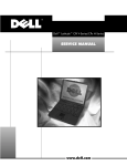
This manual provides instructions for removing and replacing field-replaceable
components, assemblies, and subassemblies in your Dell Latitude portable
computer. Unless otherwise noted, each procedure in this chapter assumes
the following:
The computer and any attached peripherals are turned off, and the peripherals
are disconnected from the input/output (I/O) panel on the back of the
computer.
A part can be replaced by performing the removal procedure in reverse order.
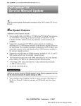
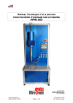
When the display assembly is open nearly 180 degrees, use a book or something
similar to support it. The angle of the display assembly with respect to the
bottom case should never be allowed to exceed 180 degrees. Also, when
performing the procedures in this manual, the locations or directions relative
to the computer are as shown in Figure 1 unless otherwise specified.
back of computer
right side
left side
front of computer
Dell Latitude CPi A Service Manual
1
Most of the procedures in this manual require the use of one or more of the
following tools:
Number 0 and number 1 magnetized Phillips-head screwdrivers
Small flat-blade screwdriver
Small plastic scribe
Processor extractor
Before you start to work on the computer, perform the following steps:
1. Save any work in progress and close all open applications.
2. Turn off the computer and any attached peripherals.
NOTE: Make sure the computer is turned off and not in suspend-to-disk
mode. If you cannot shut down the computer using the computer’s operating
system, press the power button for 4 seconds.
3. If the computer is docked in a C/Dock Expansion Station or C/Port Advanced
Port Replicator (APR), undock the computer.
4. Disconnect the computer and any attached peripherals from AC power
sources to reduce the potential for personal injury or shock. Also disconnect
any telephone or telecommunications lines from the computer.
5. Remove the power cord.
6. Disconnect all other external cables from the computer.
7.
Remove any installed PC Cards.
#$$
%
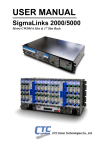
8. Remove the main battery assembly from the battery bay.
Slide the battery bay latch away from the center of the computer. Then slide
the battery out of the battery bay (see Figure 2).
2
Dell Latitude CPi A Service Manual
9. Ground yourself by touching the unpainted metal surface of the I/O panel on
the back of the computer.
While you work, periodically touch the I/O panel to dissipate any static
electricity that might harm components.
The illustrations in the following removal procedures provide the correct screw
length as part of the screw’s label. A graphic for that length screw is also included
in the illustration. Examples are shown in Figure 3. Match the actual screw to the
graphic in the illustration to check for correct length.
!"
%
%#$
%
Dell Latitude CPi A Service Manual
3
Some of the computer’s interface connectors are zero insertion force (ZIF)
connectors. These connectors are not removable, but they must be released
to disconnect a cable from them (see Figure 4).
movable part of
connector
(do not remove)
#$ "
&'
%
To disconnect an interface cable from a ZIF connector, perform the following
steps:
1. Insert a small flat-blade screwdriver under the movable part of the
connector.
2. Pull gently upward on the movable part of the connector until it releases
the interface cable.
3. Grasp the interface cable and pull it out of the connector.
To reconnect an interface cable to a ZIF connector, perform the following
steps:
1. Use a small flat-blade screwdriver to open the movable part of the ZIF
connector.
2. Orient the end of the interface cable with the ZIF connector, and insert the
end of the cable into the connector.
3. While holding the cable in place, close the ZIF connector.
To ensure a firm connection, make sure the ZIF connector is completely
closed.
4
Dell Latitude CPi A Service Manual
!"#"
Table 1 lists the parts and assemblies available for the computer. Some parts
may only be available as part of a service kit or assembly and are provided for
reference only. The subsections that follow Table 1 provide instructions for
removing and replacing these parts and assemblies.
%&!
Customer kit, AC adapter
CUS,ADPT,AC,EXT,20V,70W,
NBK,CPi A
AC adapter
ADPT,AC,EXT,20V,70W,3WIRE,
CPi A
Power cable, U.S.
CORD,PWR,110V,6F,AC,3W\3P,US
Service kit, audio board
SVC,PWA,AUDIO,CPi A
22
Audio shield
SHLD,W/SPR,AUDIO CRD
22
Service kit, back cover assembly
SVC,SUBASSY,
BK CVR/DOOR,I/O,CPi A
11
Back cover assembly
ASSY,BK PLT/DOOR,I/O,CPi A
Docking bar
BAR,DOOR,DCKG,MET
Docking door
DOOR,DCKG,PLSTC,I/O
!
Customer kit, main battery
CUS,BTRY,MN,14.4V,8CELL,
LITH
Main battery
2
BTRY,MN,14.4V,8CELL,LITH
"!
Service kit, reserve battery
SVC,BTRY,RSRV,7.2V,30MAH,6,
NIHD
Reserve battery
BTRY,RSRV,7.2V,30MAH,6,
NIHD
Reserve battery sponge pad
PAD,FOAM,BRTY,RSRV,CPi A
31
Bottom case assembly
ASSY,CVR,BTM,PLSTC,
BASE,CPi A
5, 26
Dell Latitude CPi A Service Manual
5
%&!
Bottom case bracket assembly
ASSY,BRKT,CASE,BTM
20, 23
#$" #
Service kit, CD-ROM drive
SVC,SUBASSY,CD,24X,NBK
CD-ROM drive bezel
BZL,CD
24X CD-ROM drive
CD,680M,INT,NBK
CD-ROM drive interface
board
PWA,CD/FDD INTERCONN,SE
Bottom CD-ROM drive cover
CVR,BTM,PLSTC,CD,CPi A
Top CD-ROM drive cover
CVR,TOP,PLSTC,CD,CPi A
CD-ROM drive shield
SHLD,CD,CPi A
CD-ROM drive label
LBL,REG,CD,24X
21
##
Diskette drive service kit
SVC,SUBASSY,FD,F3,
INT/EXT,CPi A
Diskette drive subassembly
SUBASSY,FD,F3,INT/EXT,CPi A
Diskette drive
FD,F3,CPi A
Diskette drive assembly bottom cover
CVR,BTM,PLSTC,FD,F3,CPi A
Diskette drive assembly top
cover
CVR,TOP,PLSTC,FD,F3,CPi A
Diskette drive assembly
interface board
PWA,INTFC,FD,F3,CPi A
Diskette drive assembly interface cable
CBL,FPC,FD,F3,CPi A
Diskette drive assembly
shield
SHLD,FD,F3,CPi A
21
%&
Service kit, exhaust fan
6
SVC,FAN,25X25X10,CPi A
Dell Latitude CPi A Service Manual
29
%&!
'$##
Hard-disk drive, subassembly
SUBASSY,HD,xxxxx,I,yyyMM,
CPi A*
Hard-disk drive
HD,xxxxx,I,yyMM,NBK,zzz*
Hard-disk drive interface
board
PWA,INTERCONN,HD,CPi A
Hard-disk drive bracket
BRKT,HD,CPi A
6
'$##(#
Hard-disk drive carrier bracket/
door assembly service kit
SVC,ASSY,BRKT/DOOR,
HD,CPi A
Hard-disk drive carrier door
DOOR,HD,12.5MM,CPi A
Hard-disk drive carrier
bracket
BRKT,HD,12.5MM,CPi A
Hard-disk drive carrier
insulator
INSUL,HD,CPi A
Hard-disk drive carrier
screws
SCR,M3X3,PHH,LP,ZPS
6
)("
Service kit, I/R board
SVC,PWA,FAST IR,CPi A
30
*
Keyboard, Belgian
KYBD,88,BEL,CPi A
Keyboard, Chinese
KYBD,87,CHI,CPi A
Keyboard, Danish
KYBD,88,DEN,CPi A
Keyboard, French
KYBD,88,FR,CPi A
Keyboard, French/Canadian
KYBD,87,FR CAN,CPi A
Keyboard, German
KYBD,88,GER,CPi A
Keyboard, Italian
KYBD,88,ITALIAN,CPi A
Keyboard, Japanese
KYBD,90,JPN,CPi A
Keyboard, Korean
KYBD,87,KOR,CPi A
Keyboard, Latin American
KYBD,88,LAC,CPi A
Keyboard, Norwegian
KYBD,88,NOR,CPi A
Keyboard, Portuguese
KYBD,88,PORTUGEUSE,CPi A
*
10
Substitute the drive capacity for xxxxx, the drive height for yy, and the
manufacturer for zzz.
Dell Latitude CPi A Service Manual
7
%&!
*
Keyboard, Russian
KYBD,87,RUS,CPi A
Keyboard, Spanish
KYBD,88,SPN,CPi A
Keyboard, Swedish/Finnish
KYBD,88,SWE,CPi A
Keyboard, Swiss
KYBD,88,SWI,CPi A
Keyboard, Thai
KYBD,87,THAI,CPi A
Keyboard, English (U.K.)
KYBD,88,UK,CPi A
Keyboard, English (U.S.)
KYBD,87,DOM,CPi A
#
Display top-cover service kit,
13.3/12.1-inch display
SVC,ASSY,CVR,TOP,LCD,CPi A
Display top cover
CVR,TOP,LCD,TFT,CPi A
Display top-cover EMI shield
SHLD,EMI,DIS,TFT,CPi A
+#
,-./-$)#
12.1-inch LCD/Cable service kit,
including LCD, brackets, cable,
and inverter
SVC,LCD/CBL/INV,TFT,zzz,12.1”,
CPi A*
16, 17
Bezel service kit, 12.1-inch
display
SVC,BZL,LCD,12.1”,CPi A
15
Display assembly bezel
BZL,LCD,TFT,12.1”,CPi A
Bezel retaining screw covers, upper corners, 12.1-inch
display
CVR,SCR,TOP,RND,ADH
Bezel retaining screw covers, lower
CVR,SCR,BTM,OVAL,ADH
Display-assembly-bezel retaining screw covers, latch,
12.1-inch display
CVR,SCR,TOP,OVAL,SM,ADH,12.1
+#
,-0/0$)12#
13.3-inch LCD/Cable service kit,
including LCD, brackets, cable,
inverter, and bezel
SVC,LCD/CBL/INV,TFT,zzz,13.3”,
CPi A*
18, 19
+#+
Latch service kit
*
8
SVC,LATCH,DIS,BZL,CPi A
Substitute the drive capacity for xxxxx, the drive height for yy, and the
manufacturer for zzz.
Dell Latitude CPi A Service Manual
14, 15
%&!
+#, 13.3/12.1-inch display
Right hinge
HNG,RT,LCD,TFT
14, 15
Left hinge
HNG,LF,LCD,TFT
14, 15
Customer kit, memory
module, 32-MB
32MB,DIMM,SDRAM,LAT CPi A,FACT
Customer kit, memory
module, 64-MB
64MB,DIMM,SDRAM,LAT CPi A,FACT
Customer kit, memory
module, 128-MB
128MB,DIMM,SDRAM,LATCPiA,FACT
#
Service kit, memory door
assembly
SVC,SUBASSY,DOOR,
MEM/BIOS,CPi A
Memory/BIOS door
subassembly
7
SUBASSY,DOOR,
MEM/BIOS,NB,CPi A
Touch-pad bracket
BRCKT,TPAD,CPi A
13
Air flow duct
GDE,INTK,AIR,FAN,PLSTC,CPi A
26
Service kit, palmrest assembly
SVC,SUBASSY,PLMRST,CPi A
Palmrest assembly
ASSY,PLMRST,GRY,CPi A
Power button
SWT,PWR SW, CPi A
Power button spring
SPR,PWR SW,CPi A
12
Dell Latitude CPi A Service Manual
9
%&!
LCD panel
SCR,M2X4.5,PHH,LP,ZPS
16, 18
LCD hinge
SCR,M3X5,PHH,LP,ZPS
14
LCD bezel
SCR,M2X4.5,PHH,LP,ZPS
15
Keyboard
SCR,M2.6X12,PHH,LP,ZPS
10
Thermal cooling assembly
SCR,M2X3.5,PHH,LP,ZPS
26
Touch pad
SCR,M2.6X1.8,PHH,XLP,ZPS
13
Palmrest, front edge
SCR,M2.6X12,PHH,LP,ZPS
12
Palmrest, hard-disk drive area
SCR,M2.6X5,PHH,LP,ZPS
12
I/R board
SCR,M2.6X5,PHH,LP,ZPS
30
Back cover
SCR,M2.6X5,PHH,LP,ZPS
11
Audio board
SCR,M2.6X5,PHH,LP,ZPS
22
Bottom-case bracket
SCR,M2.6X5,PHH,LP,ZPS
23
Exhaust fan
SCR,M2.6X12,PHH,LP,ZPS
29
Left speaker assembly
SUBASSY,SPKR,LF,W/WIRES
Right speaker assembly
SUBASSY,SPKR,RT,W/WIRES
10
System board assembly, CPi A,
service kit
SVC,ASSY,PRM/PWA,ENGINE,CPi A
System board assembly, CPi A,
service kit
SVC,ASSY,PRM/PWA,ENGINE,CPi A
Service tag installation
diskette
DSK,BIOS,FLDSVC,F3,US,CP
BIOS flash diskette
KIT,BIOS,FLASH,UPG,F3,CP
Diagnostic diskette
KIT,DSK,DIAG,F3,CPi A,WW
System board assembly
ASSY,PRM/PWA,ENGINE, CPi A
Dell Latitude CPi A Service Manual
26
%&!
System board assembly
(400 MHz processor with
13.3-in display;
366 MHz processor with
12.1-in display)
ASSY,PRM/PWA,ENGINE,
CPi A
System-board engine
subassembly
SUBASSY,PWA/ENGINE,CPi A
I/R board
PWA,FAST IR,CPi A
Microphone boot
GRMT,RBR,BOOT,MCPHN
Main system board
PWA,PLN,0M,NB,CPi A
Video/PC Card board
PWA,DTRBD,VID/PCMCIA,CPi A
LED board
PWA,LED,CPi A
Exhaust fan and cable
FAN,25X25X10,CPi A
Microphone
MCPHN,CPi A
Reserve battery
BTRY,RSRV,7.2,30MAH,6,NIHD
Foam pad
PAD,FOAM,BTRY,RSRV,CPi A
3
Service kit, thermal cooling
subassembly
SVC,SUBASSY,HTSNK,
CPU,HYB,CPi A
26
3
Touch-pad service kit
Touch-pad subassembly
SVC,TPAD,SQ,INTFC,CPi A
13
TPA,INTFC,CPi A
Dell Latitude CPi A Service Manual
11
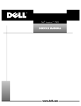
$
!"
#"
display
assembly
keyboard
palmrest
assembly
back cover assembly
main battery
modular bay
device
bottom case assembly
'()!!*+
The following subsections provide instructions for removing and replacing
field-replaceable parts and assemblies.
12
Dell Latitude CPi A Service Manual
5-mm screws (2)
hard-disk drive door
,-!.$/$
(
$
$)
*+,(
$
-%
#$$
1. Turn the computer over, and remove the two 5-mm screws from the
hard-disk drive door.
The drive is on the left side of the computer.
2. Grasp the drive door and pull the drive out of the computer.
Dell Latitude CPi A Service Manual
13
indentation
memory module cover
0!
#$$
1. Close the display, and turn the computer upside down on a flat work surface.
2. Release the memory module cover.
Insert a fingertip in the indentation in the bottom case assembly and lift the
cover slightly; then slide the cover in the direction indicated by the arrow on
the cover.
14
Dell Latitude CPi A Service Manual
memory module sockets (2)
retaining clips (2 per socket)
1!
1. Remove the memory module cover.
2. To avoid possible damage to the memory module from electrostatic
discharge (ESD), ground yourself by touching the unpainted metal surface
of an I/O connector on the computer’s back panel.
3. To release a memory module from its socket, gently push outward on each
of the memory module’s two metal retaining clips.
The memory module rotates upward out of its retaining clips.
4. Lift the memory module out of its socket.
You can install memory modules only one way. Do not attempt to force the
memory module into the socket. Align the notch near the center of the memory
module with the corresponding key in the memory module socket.
Dell Latitude CPi A Service Manual
15
To remove the keyboard assembly, perform the following steps.
#$$
1. Close the display assembly, and turn the computer upside down on a flat
work surface (see Figure 9).
12-mm screws (6)
23!
2. Remove the six 12-mm screws securing the keyboard to the computer.
3. Turn the computer right-side up and open the display.
$$
%
%
(
.
$
4. Release the keyboard from the palmrest assembly:
a. Carefully deflect the palmrest (next to the blank key below the <Shift>
key; see Figure 10) away from the center of the keyboard, until the tab on
the palmrest’s inner edge disengages from the keyboard. The keyboard
should raise up slightly.
b. Insert a fingernail or a small flat-bladed screwdriver under the scalloped
edge of the blank key (see Figure 10), and lift the right edge of the
keyboard.
16
Dell Latitude CPi A Service Manual
metal tabs (2)
keyboard
plastic
tabs (2)
scalloped edge
of blank key
palmrest
deflect palmrest outward
to release keyboard
43!
5. Once the keyboard is fully released from the palmrest, place the keyboard
upside down over the touch pad.
6. Disconnect the keyboard cable from connector KB1 on the system board.
7.
Remove the keyboard assembly.
Perform the following steps when you replace the keyboard assembly:
KB1 on the system board.
1. Connect the keyboard cable to connector
2. Fit the left edge of the keyboard into place, making sure the two small
metal tabs on the keyboard fit under the corresponding plastic tabs on
the palmrest’s inner edge.
3. Lower the right edge of the keyboard into place, and press on the blank key
below the <Shift> key until the tab on the palmrest’s inner edge engages the
keyboard with an audible “click.”
4. Check that the keyboard is correctly installed. The keys should be flush with
the left and right surfaces of the palmrest.
5. Reinstall the six 12-mm screws.
Dell Latitude CPi A Service Manual
17
5-mm screws (12)
/
1.
Close the display.
2.
Remove the twelve 5-mm screws securing the back cover:
Five screws on the underside of the back cover
One screw behind the docking connector door
Six screws on the face of the back cover
3. Close the docking connector door.
4. Remove the back cover assembly.
Grasp the right end of the back cover assembly firmly, and unsnap it from
the computer. Then disengage the left end of the back cover assembly.
18
Dell Latitude CPi A Service Manual
The palmrest assembly consists of the touch pad and the palmrest.
5-mm screw
palmrest assembly
5-mm screws (2)
bottom
case assembly
12-mm screws (3)
&
1. Remove the keyboard.
2. Disconnect the touch-pad cable from ZIF connector JP2 on the system board.
3. Remove the back cover assembly.
4. Remove the following screws securing the palmrest to the computer:
One 5-mm screw inside the computer, adjacent to the thermal cooling
assembly.
Two 5-mm screws inside the upper edge of the hard-disk drive bay.
(You must remove the hard-disk drive to access these screws.)
Three 12-mm screws underneath the front edge of the computer.
Dell Latitude CPi A Service Manual
19
5. Turn the computer right-side up on the work surface, and open the display
assembly 180 degrees.
NOTE: Support the display assembly with a book or similar object so that
the display assembly does not open beyond 180 degrees.
6. Carefully remove the palmrest assembly from the bottom case assembly.
The palmrest assembly is secured in the bottom case assembly by four snaps
and tabs on the right and left ends of the palmrest. Take care not to damage
the snaps when removing the palmrest.
NOTE: When you replace the palmrest, ensure that the vertical tab at the back of
the palmrest fits on the outside of the system board assembly, near the parallel
port connector. Also, check that the microphone boot is properly located in its
slot on the top electromagnetic interference (EMI) shield and is fitted within the
palmrest assembly.
1.8-mm screws (4)
touch-pad bracket
interface connector J1
touch-pad interface module
touch-pad cable
palmrest assembly
%5.&! "!
1. Remove the palmrest assembly.
2. Turn the palmrest assembly upside down on a flat work surface.
3. Remove the four 1.8-mm screws securing the touch-pad bracket.
20
Dell Latitude CPi A Service Manual
4. Carefully disconnect the touch-pad cable from ZIF connector J1 on the
touch-pad interface module.
To release the ZIF connector latch, use a fingernail to lift up the central portion
of the black plastic latch.
5. Remove the touch-pad interface module from the palmrest.
1. Remove the palmrest assembly.
2. Turn the palmrest assembly upside down on a flat work surface.
3. Compress the two catches securing the power button, and remove the
power button and spring from the palmrest assembly.
!
display assembly
black 5-mm displayassembly interfacecable grounding
screws (2)
5-mm screws (4)
display-assembly
interface cable
hinges (2)
#$
Dell Latitude CPi A Service Manual
21
1. Remove the back cover assembly.
2. Remove the keyboard.
3. Remove the palmrest assembly.
4. Remove the two black 5-mm interface-cable grounding screws and the
interface cable bracket.
5. Disconnect the display-assembly interface cable from connector JP1 on the
system board.
Grasp the grounding tabs and pull the connector straight up from the system
board.
6. Close the display, being careful not to damage the display-assembly interface
cable.
7.
Remove the four silver 5-mm screws securing each of the two hinge brackets
to the bottom case assembly.
8. Lift the display assembly from the bottom case assembly.
NOTE: When you reinstall the display assembly, install the four screws securing
the hinges at the locations marked by arrows on the face of each hinge.
(
%
/
22
Dell Latitude CPi A Service Manual
!
"
4.5-mm screws (4)
screw covers (6)
display assembly bezel
5-mm screws (2)
display-assembly
top cover
'$67. 5$58
1. Use a scribe to carefully pry the screw covers out of the six screw holes in
the bezel.
2. Remove the six screws from the bezel.
The four upper screws are 4.5-mm screws, while the two lower screws are
5-mm in length.
3. Separate the bezel from the display-assembly top cover.
The bezel is secured by snaps around all four of its edges. Insert your
fingertips between the bezel and the LCD panel, and lift upward on the bezel
to release the hidden snaps. Avoid pressing on the surface of the LCD panel.
!
#
NOTE: On a 13.3-inch display, you must remove the LCD panel before you can
remove the display assembly latch.
1. Remove the display assembly bezel.
2. Remove the display assembly latch by unsnapping the latch and captive
spring from the inside of the display assembly top-cover assembly.
Dell Latitude CPi A Service Manual
23
#
The following subsections describe how to remove an LCD panel.
4.5-mm screws (2)
LCD panel
LCD panel
power cable
interface
connector
LCD inverter board
display-assembly top cover
,9
$&7. 5$8
1. Remove the back cover assembly.
2. Remove the keyboard.
3. Remove the palmrest.
4. Remove the display assembly bezel.
5. Remove the two 4.5-mm screws at the right corners of the LCD panel.
6. Remove the two screws holding the interface connector.
7.
Disconnect the interface connector.
Figure 17 shows the cable layout for a 12.1-inch LCD panel.
24
Dell Latitude CPi A Service Manual
8. Use the yellow tab to lift the right side of the LCD panel, slide the LCD panel
to the right, and then lift the LCD panel out of the top cover.
NOTE: Remove and replace the LCD as a whole assembly.
inverter
connector
LCD
connector
interface
connector
0
9"5. 59
$&
Dell Latitude CPi A Service Manual
25
LCD panel
4.5-mm screws (2)
interface cable
LCD inverter board
display-assembly top cover
LCD panel
power cable
19
$&7. 5$8
1. Remove the display assembly bezel.
2. Remove the two 4.5-mm screws at the right corners of the LCD panel.
3. Use the yellow tab to lift the right side of the LCD panel, slide the LCD panel
to the right, and then pivot the panel up.
4. Remove the connector tape from the interface cable at the center-junction
connector on the back of the LCD panel (see Figure 19).
5. Disconnect the interface cable at the center-junction connector.
$
Figure 19 shows the two-piece (A and B) cable layout for a 13.3-inch LCD
panel.
26
Dell Latitude CPi A Service Manual
6. Disconnect the display-assembly interface cable from the ZIF connector on
the inverter that is located on the right side of the LCD panel.
To disconnect the cable, carefully work the cable connector free from the ZIF
connector on the LCD panel. Do not pull on the LCD interface cable itself.
NOTES: When you replace the 13.3-inch LCD display, always replace the display
assembly bezel with the new one that comes with the LCD display.
If you need to replace the bottom LCD cable on the 13.3-inch display, use one
bend to route the new cable to the inverter board connector.
If you need to replace the bottom LCD cable on the 12.1-inch display, use two
bends to route the new cable to the inverter board connector.
LCD B cable
(stays with LCD panel)
connector
tape
center-junction
connector
inverter
connector
LCD A cable
interface
connector
2%.&
9"5. 59
$&
Dell Latitude CPi A Service Manual
27
#
!
$
1. Remove the LCD display assembly from the computer.
2. Remove the display assembly bezel.
3. Remove the four silver 5-mm screws securing the two hinge brackets to the
display-assembly top cover.
NOTE: To aid in reinstalling the hinges and display assembly, the right and left
hinges are marked by an “R” and an “L,” respectively. Install the four screws
securing the hinges at the locations marked by arrows on the face of each hinge.
!
!
1. Remove the display assembly.
2. Remove the display assembly bezel.
3. Remove the LCD panel.
4. Remove the display assembly latch.
5. Remove the left and right hinges.
6. Remove the display-assembly interface cable.
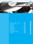
The bottom case assembly consists of the following field-replaceable
components:
Modular bay device (diskette drive assembly, CD-ROM drive assembly,
or travel module)
Back cover assembly
Audio shield
Audio board
Bottom case bracket
Module latch assemblies
Speakers
System board assembly
Thermal cooling assembly
Air flow duct
Exhaust fan
Infrared (I/R) board
Reserve battery
28
Dell Latitude CPi A Service Manual
audio board
audio shield
thermal cooling assembly
I/R board
system board assembly
bottom case bracket
air flow duct
module latch
assembly (2)
main battery
exhaust fan
speakers (2)
modular bay device
4
Dell Latitude CPi A Service Manual
29
%
&
'( &
&
)
latch lock
!$
NOTE: You do not need to remove the main battery or hard-disk drive prior to this
procedure.
#$$
1. Close the display and turn the computer over.
2. Remove the device from the modular bay.
Push the modular bay latch away from the center of the computer. Keep
holding the latch open while pulling the device out of the modular bay with
the other hand.
*
1. Remove the back cover assembly.
2. Remove the keyboard assembly.
3. Remove the palmrest assembly.
4. Remove the 5-mm screw securing the audio shield (see Figure 22).
5. Remove the 5-mm screw securing the EMI drain wire.
6. Remove the audio shield.
NOTE: When you replace the audio shield, ensure that the audio shield is
properly seated to prevent it from cutting into the speaker wires or interfering
with devices installed in the modular bay. (You can check this by temporarily
installing a device in the modular bay prior to reinstalling the palmrest assembly.)
30
Dell Latitude CPi A Service Manual
5-mm screw
audio shield
microphone
connector
audio board
speaker
connectors
speaker wires
!!
1. Remove the back cover assembly.
2. Remove the keyboard assembly.
3. Remove the palmrest assembly.
4. Remove the 5-mm screw securing the audio shield.
5. Remove the 5-mm screw securing the EMI drain wire.
6. Remove the audio shield.
7.
Disconnect the speaker wires and microphone wire from their connectors
on the audio board.
The connectors are fragile—do not pull on the wires to disconnect them.
8. Remove the audio board from the bottom case.
NOTE: When you replace the audio shield, ensure that the audio shield is
properly seated to prevent it from cutting into the speaker wires or interfering
with devices installed in the modular bay. (You can check this by temporarily
installing a device in the modular bay prior to reinstalling the palmrest assembly.)
Dell Latitude CPi A Service Manual
31
left speaker
left speaker wires
plastic retaining clip
5-mm screws (3)
slot
right speaker
/
1. Remove the back cover assembly.
2. Remove the keyboard assembly.
3. Remove the palmrest assembly.
4. Remove the 5-mm screw securing the audio shield and the 5-mm screw
securing the EMI drain wire.
5. Remove the audio board shield.
6. Disconnect the speaker wires from connectors JP1 and JP2 on the audio
board.
The connectors are fragile—do not pull on the speaker wires to disconnect
them.
7.
Remove the two 5-mm screws on the left side and one 5-mm screw on the
right side of the bottom case bracket.
8. Insert the end of a small flat-blade screwdriver into the slot in the vertical
support in the center of the bottom case, and disengage the plastic retaining
clip.
9. Lift the bottom case bracket from the computer.
32
Dell Latitude CPi A Service Manual
NOTE: When you replace the bottom case bracket, follow these guidelines to
prevent damage to the speaker wires:
Orient each speaker in the bottom case so that its wires are facing upwards.
Route the speaker wires under their respective retaining clips on the bottom
case bracket.
#
module latch
assemblies (2)
plungers (2)
springs (2)
module latches (2)
#!95
1. Remove the bottom case bracket.
2. Remove the left latch from the outside of the bottom case by unsnapping
the slider-spring assembly.
Keep pressure applied to the slider-spring assembly while unsnapping the
latch to prevent the slider-spring assembly from coming loose from the case.
If the slider-spring assembly does come loose from the case:
a. Carefully reinsert the spring onto the plunger on the slider, and reinstall
the slider-spring assembly into the holding features on the inside of the
case.
Dell Latitude CPi A Service Manual
33
b. Ensure that the plunger is inserted in its respective hole, that the side
of the slider with the two bumps is facing the rear of the case, and
that the surface with the wear ribs is facing the bottom of the case
(see Figure 25).
3. Snap in the new latch from the bottom of the base, making certain its snap
features are fully engaged in the slider.
4. Ensure that the newly installed latch moves smoothly and freely when
pushed and released.
5. Repeat steps 1 through 4 for the latch on the right side.
6. On the base plastic, find the molded label “P.N. ASSY 89501”; then use a
permanent marker to write “A01” to the right of “89501.”
This revision mark indicates that the latch rework is complete.
bump side
wear ribs (2)
'9"!
*!
1. Remove the bottom case bracket.
2. If you are replacing the left speaker, carefully remove the speaker wires from
the retaining clips along the bracket’s edges.
3. Remove the speaker from the bottom case bracket.
NOTE: When you replace the speaker, follow these guidelines to prevent damage
to the speaker wires:
Orient the speaker in the bottom case so that the speaker wires are facing
upwards.
Route the speaker wires under their retaining clips on the bottom case
bracket.
34
Dell Latitude CPi A Service Manual
*
3.5-mm screws (2)
thermal cooling assembly
system board assembly
air flow duct
5-mm screws (2)
3.5-mm screw
bottom case assembly
,!
The system board’s basic input/output system (BIOS) chip contains the system
service tag number, which is also visible on a bar-code label on the bottom of the
computer. The replacement kit for the system board assembly includes a diskette
that provides a utility for transferring the service tag number to the replacement
system board assembly.
1. Remove the back cover assembly.
2. Remove the keyboard assembly.
3. Remove the palmrest assembly.
Dell Latitude CPi A Service Manual
35
0
%
*-
$
4. Remove the two 3.5-mm screws securing the TCA to the microprocessor
module.
5. Remove the TCA from the microprocessor module.
6. If a processor hold-down clip is attached to the processor module fence,
remove the clip.
Your computer may have a one- or two-slot hold-down clip. One tab locks the
one-slot hold-down clip to the fence. Two tabs lock the two-slot clip to the
fence. To remove the clip, perform the following steps to bend the tabs away
from the fence:
a. Insert a small flat-blade screwdriver into one of the slots at the top of the
clip (see Figure 27).
b. Bend the tab away from the fence by carefully tipping the screwdriver
away from the processor module.
c. If your computer has a two-slot hold-down clip (see Figure 27), repeat
substeps a and b for the second slot .
d. Lift the clip off the fence and discard it.
36
Dell Latitude CPi A Service Manual
processor-module fence
slot
one-slot hold-down clip
processor-module fence
slots
two-slot hold-down clip
0.!%.-!.$
7.
Remove the three screws that secure the processor module to the system
board.
8. Use a processor extractor tool to remove the processor module.
The tool fits on the left side of the module, in the notches.
/
1
0
9. Remove the air flow duct.
10. Verify that the PC Card ejectors do not extend from the PC Card bay.
11. Remove the 2.5-mm screw from the center of the computer’s left rear foot.
Dell Latitude CPi A Service Manual
37
12. Remove the following two screws from the system board assembly
(see Figure 26):
The 5-mm screw near the reserve-battery cable connector
The 5-mm screw near the microprocessor module
13. Lift the system board assembly out of the bottom case assembly.
Be sure to transfer the memory module(s) to the replacement system board
assembly. If you are replacing the thermal cooling assembly with a new one,
remove any lining present on the thermal pad before installing the new thermal
cooling assembly.
After replacing the system board assembly, be sure to enter the system’s service
tag number into the BIOS of the replacement system board assembly. Insert the
diskette that accompanied the replacement system board assembly into the
diskette drive, and turn on the computer. Follow the instructions on the display.
When you reinstall the microprocessor module in the system board, make sure
you press down evenly at all four corners of the module. When the
microprocessor module is seated, all four corners must be at the same height. If
one or more corners of the module are higher than the others, the module is not
seated correctly. To ensure the microprocessor module is seated correctly, look
at the holes on the processor-module fence. You should see no less than the top
half of the holes all the way around the microprocessor module (see Figure 28).
Install the three screws to secure the microprocessor module to the system
board. Place a new processor hold-down clip (either a one-slot or two-slot clip)
over the corner of the fence as shown in Figure 28. Press the clip down to lock it
in place. Do not reuse the old clip.
processor hold-down clip
(one-slot clip shown)
processor-module
fence holes
1!
38
Dell Latitude CPi A Service Manual
+,
-
exhaust fan power cable
connector (JFAN1)
12-mm screws (2)
exhaust fan
2()5
1. Remove the back cover assembly.
2. Remove the keyboard assembly.
3. Remove the palmrest assembly.
4. Disconnect the exhaust fan power cable from connector J10 on the system
board.
5. Remove the two 12-mm screws securing the exhaust fan, and then remove
the exhaust fan.
NOTE: When you replace the exhaust fan, orient the fan so that the fan label
faces outward and the power cable is at the upper-right corner of the fan (when
viewed from the back of the computer). (This prevents the fan wires from being
pinched when you reassemble the computer.) Make sure that the wires are
routed under the upper EMI shield.
Dell Latitude CPi A Service Manual
39
.'
5-mm screw
I/R board
4 :!
1. Remove the palmrest assembly.
2. Remove the 5-mm screw securing the I/R board to the system board
assembly.
3. Lift the I/R board straight up from the system board assembly.
40
Dell Latitude CPi A Service Manual
'
reserve battery
reserve battery cable
connector (JBAT1)
2
(
$*!-
(
*3!#-
!
(
3!#
%$
To remove the reserve battery, perform the following steps:
1. Remove the back cover assembly.
2. Remove the keyboard assembly.
3. Remove the palmrest assembly.
4. Disconnect the reserve battery cable from connector JRBAT1 on the system
board.
5. Remove the reserve battery from the bottom case bracket.
a. Tear the reserve battery free from the foam pad.
b. Remove the remnants of the foam pad from the system board assembly.
NOTE: When you replace the reserve battery, first connect the reserve battery
cable to the system board. Then position the reserve battery on the hard-disk
drive bay so that there is minimal slack in the cable.
Dell Latitude CPi A Service Manual
41
42
Dell Latitude CPi A Service Manual
#
'
audio board
removal, 31
ESD, 2
audio shield
removal, 30
%
back cover assembly
removal, 18
battery (in modular bay)
removal, 30
bottom case assembly
components, 28
illustrated, 29
exhaust fan
removal, 39
field-replaceable parts and assemblies
illustrated, 12
list of, 5
(
hard-disk drive assembly
removal, 13
bottom case bracket
removal, 32
I/R board
removal, 40
CD-ROM drive
removal, 30
)
&
keyboard assembly
removal, 16
diskette drive
removal, 30
display assembly
bezel, removal, 23
removal, 21
top cover, removal, 28
Index
1
*
LCD display hinge
removal, 28
reserve battery
removal, 41
LCD panel
removal, 24, 26
+
main battery assembly
removal, 2
memory module
removal, 15
memory module cover
removal, 14
modular bay devices
removal, 30
screw identification and tightening, 3
sockets
memory module, 15
speakers
removal, 34
system board assembly
removal, 35
module latch assemblies
removal, 33
tools, 2
module latch assemblies removal, 33
touch-pad interface module
removal, 20
travel module
removal, 30
palmrest assembly
removal, 19
power button
removal, 21
preparing to work, 2
2
Dell Latitude CPi A Service Manual
ZIF connectors, 4