1
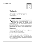
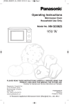
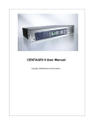
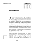
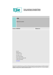
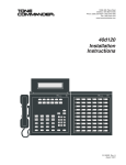
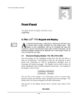
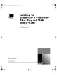
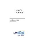
Prima LT U S E R S G U I D E a Appendices Appendix A — Cable Diagrams Cable C1300. DB15M To V.35 Block A-1 Prima LT U S E R S G U I D E Cable C1500 —AES Adapter Cable C1700 — Ancillary Data And RS232 Cable Cable C1800 — Rear Panel RS232 Remote Control Cable A-2 Prima LT U S E R S G U I D E Cable C1900 — Rear Panel RS485 Remote Control Cable A-3 Prima LT U S E R S G U I D E Appendix B — Rear Panel Connectors Audio Output Connector: Male XLR Audio Input Connector: Female XLR 1 2 3 Ground + - 1 2 3 Ground + - AES/EBU Connector: AMP 747158-8 (Female DB9) Digital Audio Input 1 IN+ 6 IN2 Ground Digital Audio Output 4 OUT + 9 OUT 5 Ground Digital Audio Sync Input 3 SYNC IN + 7 SYNC IN 8 Ground RS232/RS485 Remote Control Connector: AMP 747150-8 (Female DB9) RS232 (rear panel remote control port) 4 RD (input) 9 TD (output) 5 Ground RS485 Ancillary Data Connector: AMP 747871-8 (Male DB9) 1 2 3 4 5 6 7 8 9 DCD RXD TXD DTR Ground DSR RTS CTS no connection Input Input Output Output Input Output Input B-4 1 6 2 7 3 RD- (Input) RD+ (Input) TD- (Output) TD+ (Output) Ground Prima LT U S E R S G U I D E Alarm Relay Connector: AMP 747871-8 (Male DB9) 1 2 3 4 5 6 7 8 9 Common 1 no connection Normal 2 (power on and no summary alarm (RLS) ) Common 2 Alarm 1 (power off or summary alarm (RLS) ) no connection Alarm 2 (power off or summary alarm (RLS) ) no connection Normal 1 (power on and no summary alarm (RLS) ) DIF101, DIF102 X.21 V.35 Connector: DB15F Connector: DB15F 1 fg t(a) c(a) 4 5 r(a) i(a) 6 b(a) sg t(b) c(b) 11 12 13 14 15 r(b) i(b) Frame ground Transmit data A (output) Control element A (input) Timing element A (input) Byte timing B (input) Signal ground Transmit data B (output) Control element B (input) Timing element B (input) Byte timing B (input) B-5 fg tda rts rda 6 7 Sg tdb dtr rdb rlsd 13 14 15 retb tetb Frame ground Transmit data A (output) Request to send Receive data A (input) N/C Receive timing A (input) Transmit timing A (output) Signal ground Transmit data B (output) Data terminal ready Receive data B (input) Receive line signal detect (output) Clear to send Prima LT U S E R S G U I D E Appendix C — Factory Defaults The factory default values are as follows: CAA 1 YES CAA 2 YES CAC NO CAN 2 CBR 128 CBZ NO CCV 7 CDC NO CDM CDR 9600 CEA LN0 CEA LN1 CEA LN2 CEA LN3 CEA LN4 CEA LN5 CEA LN6 CEA LN7 CEA LN10 CEA LN11 CEA ESM CEA DSM CEA RLS CEA RL0 CEA RL1 CEA RL2 CEA RL3 CEA RL4 CEA RL5 CEA RL6 CEA RL7 CEA SC1 CEA RC1 CEA VA0 CEA VA1 CEA VA2 CEA VA3 CFM 4 Wires set auto answer on for line 1 set auto answer on for line 2 set to no auto reconnect set ancillary data port to configuration 2 (mux) set loopback digital interface bit rate internal alarm buzzer inactive set LCD contrast don't display connect time clear dialing parameters set decoder DSP ancillary data rate set default link actions !OI0 !OI1 !OI2 !OI3 !OI4 !OI5 !OI6 !OI7 BER OOF !EPL !DPL # BER # OOF EPL & DPL & !BER & !OOF LN0 LN1 LN2 LN3 LN4 LN5 LN6 LN7 CI1 LN8 all Virtual Actions cleared set rear panel 485 port to 4 wires C-6 LT U S E R S G U I D E CFP NO CGH OLDPKI CHK 1 CHK 2 CID 0 CIF 1 NONE CIF 2 NONE CLB 1 NORM CLB 2 NORM CLI STATUS 10 CLL A ON CMA 2400 CPC NO CRB 9600 CRD 1 CRE YES CRI 232 CRM 4WIRES CSL LB CSP RS232 CTC NONE CTM 0 0 CTM 1 0 CTM 2 0 CTM 3 0 CTO 15 CVA 0 CVA 1 CVA 2 CVA 3 DAF CCS DAL MPEGL2 DCO ISOCCS DCS NORM DDO 48 DES NOTREQ DIN NO DMD NORM DMU NONE DSP NO DTI NORMAUTO EAF CCS EAI A set no front panel remote control protocol set to old PKI framing in H.221 mode clear all hot keys set to RS485 ID 0 set to no digital interface set to no digital interface set no digital loopback on DIF 1 set no digital loopback on DIF 2 set status led intensity set all speed dialing set mux ancillary data 2400 baud no protocol for remote communications set remote control baud rate set number of TA redial attempts to 1 set to echo rear panel commands RS232 for remote communication set RS485 remote control port to 4 wire system loopback set sync anc data interface to RS232 no connection to any TA turn off timer 0 turn off timer 1 turn off timer 2 turn off timer 3 set TA dialing time-out in seconds set virtual action 0 to empty set virtual action 1 to empty set virtual action 2 to empty set virtual action 3 to empty set decoder ancillary data format set to MPEG I layer 2 set decoder decoding mode to ISO and CCS set decoder output to no copy or swap set to 48 kHz digital output set decoder AES sync timing not required set decoder to operate together with encoder set decoder maintenance diagnostic mode to normal set decoder mute to none set to no decoder scale factor set decoder timing to normal set encoder ancillary data format set input to analog C-7 Prima U S E R S EAL MPEG2 EAM JS ESR 48 EBR 128 ECS NORM EEP NO ELU 1 EOR NO EPR YES EPY 0 1 EPY 2 1 EPY 3 2 EPY 5 3 EPY 6 1 EPY 8 1 EPY 9 3 EPY 11 3 EPY 12 4 EPY 14 1 EPY 15 3 EPY 17 3 EPY 18 4 EPY 20 3 EPY 21 3 EPY 23 1 EPY 24 1 EPY 26 4 EPY 27 3 G U I D E set to joint stereo set to no mono mix set encoder to 128K bit rate set no copyright bit set no emphasis bit set encoder line format to 2 line, line 1 & 2 set no original bit set no privacy bit off set psychoacoustic parameter type set psychoacoustic parameter type set psychoacoustic parameter type set psychoacoustic parameter type set psychoacoustic parameter type set psychoacoustic parameter type set psychoacoustic parameter type set psychoacoustic parameter type set psychoacoustic parameter type set psychoacoustic parameter type set psychoacoustic parameter type set psychoacoustic parameter type set psychoacoustic parameter type set psychoacoustic parameter type set psychoacoustic parameter type set psychoacoustic parameter type set psychoacoustic parameter type set psychoacoustic parameter type set psychoacoustic parameter type C-8 Prima LT U S E R S G U I D E EPY 28 4 EPY 29 4 EPY 30 1 EPY 31 1 ESD OFF ESP NO ESW CI0 OFF ESW CI1 OFF ESW CI2 OFF ESW CI3 OFF ESW CI4 OFF ESW CI5 OFF ESW CI6 OFF ESW CI7 OFF ETI NORM MBD 1 MBE NO MBL 1 MBP 10 MBR MBU 1 MBX ON MCP NONE MET DISABLED MLK KEYPAD NO MLK INBAND NO MLK FRONT NO MLK REAR NO MLK DIF NO MLK VA NO MOD 1 MOL 10 MOP 20 MOU 2 MQL EL -60 MQL ER -60 MQL DL -60 MQL DR -60 MQL E -60 MQL D -60 MQT EL 10 MQT ER 10 MQT DL 10 set psychoacoustic parameter type set psychoacoustic parameter type set psychoacoustic parameter type set psychoacoustic parameter type set encoder sine wave detector off set to no encoder scale factor protection set simulated switch 0 open set simulated switch 1 open set simulated switch 2 open set simulated switch 3 open set simulated switch 4 open set simulated switch 5 open set simulated switch 6 open set simulated switch 7 open set encoder timing to normal set BER count down counter disallow remote boot set BER limit to 1 set BER maximum count at 10 clear the BER counter set BER count up counter set keypad clicker on set to no connect port disable hardware tests set no command lockout from keypad set no command lockout from inband set no command lockout from front panel set no command lockout from rear panel set no command lockout from digital set no command lockout from virtual set OOF down counter set OOF limit to 10 set OOF count maximum set OOF up counter set encoder left quiet threshold level set encoder right quiet threshold level set decoder left quiet threshold level set decoder right quiet threshold level set encoder stereo quiet threshold level set decoder stereo quiet threshold level set encoder left quiet threshold time set encoder right quiet threshold time set decoder left quiet threshold time C-9 LT U S E R S MQT DR 10 MQT E 10 MQT D 10 MRS RP MTM NONE MWP NONE G U I D E set decoder right quiet threshold time set encoder stereo quiet threshold time set decoder stereo quiet threshold time set rear panel remote control source to rear set to no test measurements set to no watch port C-10 LT U S E R S G U I D E Appendix D - Useful Pull-Outs Entry Description Bit rate Sample rate Encoder algorithm Mode Line format Decoder indep. Zephyr compatible RoadRunner equivalent 0 1 2 5 6 7 8 9 10 11* 12* 13* 14* 15* 16 17 18 19 20 21 22 23 24 25 26 27 28 29 30 31 32 33 34 35 36 37 CDQ1000_24K:QS CDQ20002LNS:QS H221_2LINES:QS MICRO56:QS G.722_56K:QS G.722_64K:QS MPEGL2/64K:QS MPEGL2/56K:QS CCSN/64K:QS CCSTEST64 CCSTEST128 CCSTESTH221 CCSTEST56 CCSTEST112 CDQ1000/56K:QS CDQ2000/112:QS CCSN/56K:QS G.722_H.221:QS CCSN/128K:QS CCSN/112K:QS CDQ2001/128:QS CDQ2001/112:QS ZEPHYR/56K:QS ZEPHYR/64K:QS ZEPHYR/112K:QS ZEPHYR/128K:QS LYR3/56K:QS LYR3/64K:QS LYR3IND56:QS LYR3IND64:QS LYR3IND56/32:QS LYR3IND64/32:QS ROADRUN112:QS ROADRUN128:QS ZEPH112MONO:QS ZEPH128MONO:QS 64 128 128 56 56 64 64 56 64 64 128 128 56 112 56 112 56 64 128 112 128 112 56 64 112 128 56 64 56 64 56 64 112 128 112 128 24 48 48 16 16 16 48 48 48 48 48 48 48 56 24 48 48 16 48 48 32 32 48 48 48 48 48 48 48 48 32 32 48 48 48 48 CCSN MPEGL2 MPEGL2 G.722 G.722 G.722 MPEGL2 MPEGL2 CCSN MPEGL2 MPEGL2 MPEGL2 MPEGL2 MPEGL2 CCSN MPEGL2 CCSN G.722 CCSN CCSN MPEGL2 MPEGL2 MPEGL2 MPEGL2 MPEGL2 MPEGL2 MPEGL3 MPEGL3 MPEGL3 MPEGL3 MPEGL3 MPEGL3 MPEGL2 MPEGL2 MPEGL2 MPEGL2 M JS JS M1 M1 M1 M M M M JS JS M JS M JS M M1 JS JS JS JS M M JS JS M M M M M M M M M M L1 CCSL12 H221L12 L1 L1 L1 L1 L1 L1 L1 CCSL12 H221L12 L1 CCSL12 L1 CCSL12 L1 H221L1 CCSL12 CCSL12 CCSL12 CCSL12 L1 L1 CCSL12 CCSL12 L1 L1 L1 L1 L1 L1 CCSL12 CCSL12 CCSL12 CCSL12 NO NO NO NO NO NO NO NO NO NO NO NO NO NO NO NO NO NO NO NO NO NO YES YES YES YES NO NO YES YES YES YES NO NO YES YES NO NO NO YES YES YES NO NO NO NO NO NO NO NO NO NO NO NO NO NO NO NO YES YES YES YES NO NO YES YES YES YES NO NO YES YES 6 * — These entries dial numbers, and will not work unless an internal terminal adapter is used and an ISDN line is connected. D-11 40 40 42 10 4 10 0 4 44 5 11 24 30 25 31 23 29 14 18 15 19 Prima LT U S E R S G U I D E E-12 Prima LT U S E R S G U I D E Appendix E — Specifications All published specifications are typical and subject to change without notice. ANALOG AUDIO SPECIFICATIONS Connector Type: Input: Output: A/D & D/A converters: Sample frequencies: Input impedance: Output impedance: Clipping level: Insertion gain: System frequency response: Fs = 16 KHz FS = 24 KHz System frequency response: Fs = 32 KHz FS = 48 KHz Total harmonic distortion: Signal-to-noise ratio: Crosstalk: L/R phase difference: Compression algorithms: Gold plated Neutrik 3-pin XLR female male 24 bit sigma-delta 16, 24, 32, or 48 kHz 600 Ohms or >25 kOhm, balanced 600 Ohms or < 60 Ohms, balanced +12, +15 or +18 dBu, ± 1 dB 0 dB ±0.5 dB ±0.3 dB, ref. @ 1 kHz. MUSICAM Layer II. 20 to 7,500 Hz 20 to 11,250 Hz ±0.15 dB, ref. @ 1 kHz. MUSICAM Layer II and Layer III. 20 to 14,500 Hz 20 to 20,000 Hz <-80 dB @ 1 KHz >92 dB <-85 dB <0.5° CCS MUSICAM old CCS MUSICAM new ISO/MPEG Layer II ISO/MPEG Layer III CCITT G.722 Storage for additional algorithms E-13 Prima LT U S E R S G U I D E DIGITAL AUDIO SPECIFICATIONS Connector type: Interface type: Lock range: Rate adaption: DB9, female optional XLR adapter available AES/EBU or S/PDIF ± 200 ppm Automatic DATA INTERFACE SPECIFICATIONS Network interface types: Number of ISDN B channels supported: Bit rates: Layer II: Layer III: G.722 Auxiliary data channel Type of connector: Bit rate, direct mode: Bit rate, Mux mode Mode: Handshake: Alarm interface Type of connector: Functions: Type: ISDN BRI (2B + D), RS422, V.35, X.21 1 to 6 in parallel 24, 32, 40, 48, 56, 64, 80, 96, 112, 128, 144, 160, 192, 224, 256, 320 or 384 kb/s. 56, 64, 112, 128, 192, 256 or 320 kb/s 56 or 64 kb/s DB9, female 300, 1,200, 2,400, 9,600, or 38,400 bps 300, 1,200, 2,400, 9,600, or 19,200 bps 8 data bits, 1 stop bit None required DB9, male Summary alarm Form C contacts CONTROL INTERFACES Level indicators: Remote control, rear panel: Features controlled: Electrical interfaces: Connector: Bit rates: Mode: Handshake: Digital Control Outputs: Type: Number: Connector: Norm and Clip LED All RS232-C or RS485 DB9, male 1,200, 2,400, 4,800, 9,600, or 38,400 bits/s 8 data bits, 1 stop bit, no parity None or XON/XOFF Dry floating relay or open collector TTL 1 DPDT DB9, female E-14 Prima LT U S E R S G U I D E GENERAL Environmental Conditions: Storage temperature: -40 to +70° C (-40 to +158° F) Operating temperature: 5 to +45° C (41 to +113° F) Relative humidity: 20 to 80%, non-condensing EMC: EN 50081-1, EN 50082-2 Power requirements: 90 to 250 VAC, 47 to 65 Hz. <60 Watts Dimensions, Models 210, 220, and 230: Height: 2U (3.5”, 8.89 cm) Width: 19” (48.26 cm), rack mountable Depth: 12.2” (30.99 cm) Net weight: Approx. 14.4 lbs. (6.6 Kg) DELAY MEASUREMENTS The following measurements are typical, ±20% Bit Rate Sample Rate Algorithm Line Fmt M JS DM S 64 64 64 64 16 24 32 48 MPEGL2 MPEGL2 MPEGL2 MPEGL2 L1 L1 L1 L1 190 140 100 70 200 135 100 70 200 135 100 70 200 135 100 75 64 16 G.722 L1 - - - - M1 35 The following measurements are for the CCS 2-Line mode. Low-delay single-line delay figures are typically ½ those shown here. 128 128 128 128 16 24 32 48 MPEGL2 MPEGL2 MPEGL2 MPEGL2 CCSL12 CCSL12 CCSL12 CCSL12 E-15 265 230 135 265 230 130 265 230 160 265 230 160 Prima LT U S E R S G U I D E Frequency Response and Noise Specifications The following plots are representative of performance at the most popular configurations. These measurements were taken using the Audio Precision System One, Dual Domain analyzer and the standard test suite. E-16 Prima LT U S E R S G U I D E Appendix F — ISDN Ordering And Provisioning North American ISDN Ordering Contacts Ameritech 800-TEAMDATA AT&T 800-222-7956 Bell Atlantic 800-570-ISDN Bellcore 800-992-ISDN BellSouth 800-428-ISDN Cincinnati Bell 800-566-DATA GTE 800-888-8799 MCI 800-MCI-ISDN Nevada Bell 702-333-4811 Pacific Bell 800-4PB-ISDN Rochester Telephone 716-777-1234 SNET 203-553-2369 Sprint 913-624-4162 Stentor Canada 800-578-ISDN Southwestern Bell 800-992-ISDN US West 800-246-5226 or 303-896-8301 Wiltel 918-588-5069 North American ISDN Provisioning In an effort to make ISDN ordering and provisioning as easy as possible, we recommend faxing the following five pages to your ISDN service provider. If provisioned as shown on these pages, your IDSN circuit will work with your CDQPrima, regardless of terminal adapter used. If given a choice between AT&T Custom or National ISDN, we recommend National ISDN. Also note that when ordering ISDN service, you must ask for long distance service and specify a carrier. Unlike regular telephone service, long distance is not automatically provided. F-17 Prima LT FAX-PAGE 1 U S E R S G U I D E AT&T 5ESS Custom Request from the telephone company an ISDN line in a “Point To Point” configuration with 2B1Q line code. Your ISDN line must be configured to allow circuit switched data on both B-channels and signaling on the D-channel. Request that the telephone company program your ISDN line with the following attributes: n Maximum terminals set to 1 (this tells the switch that there is 1 terminal active on this line.) n Maximum B-channels set to 2; Actual User settings (this tells the switch that you are an actual user and may use both B-channels simultaneously.) n Circuit switched data set to 2; circuit switched data channel set to any (this tells the switch that you may use both B-channels simultaneously. The “Any” tells the switch that either B-channel can be used for data.) n Terminal type is Type A - Basic Terminal (this tells the switch you are a basic ISDN terminal.) n Display set to Yes (this tells the switch that you have display capabilities.) n Call appearance quantity set to 1 (this tells the switch that you want 1 appearance of your primary telephone number.) n Call appearance preference set to Idle (this tells the switch that your software will make a positive choice of which cal appearance it will use to initiate a call.) The Telephone Company will also need to know any additional voice features that you require on your ISDN lines. Examples of these features are Caller ID and Call Forwarding. PLEASE REMEMBER TO SPECIFY A LONG DISTANCE CARRIER. F-18 Prima LT FAX-PAGE 2 U S E R S G U I D E AT&T 5ESS - National ISDN 1 Request from the telephone company a National ISDN 1 ISDN line in a “multipoint” configuration with 2B1Q line code. The optional “multipoint” configuration will allow you to have a separate telephone number for each B-channel; however, it will physically be only one ISDN line. The Telephone Company should supply you with a different telephone number and SPID (Service Profile Identification) for each B-channel in a multipoint arrangement. Your ISDN line must be configured to allow circuit switched data on both B-channels and signaling on the D-channel. Request that the Telephone Company program your ISDN line with the following attributes: n Maximum terminals set to 2 (this tells the switch that there are 2 terminals active on this line.) n Maximum B-channels set to 2; Actual User settings (this tells the switch that you are an actual user and may use both B-channels simultaneously.) n Circuit switched data set to 2; circuit switched data channel set to any (this tells the switch that you may use both B-channels simultaneously. The “Any” tells the switch that either B-channel can be used for data.) n Terminal type is Type A - Basic Terminal (this tells the switch you are a basic ISDN terminal.) n Display set to Yes (this tells the switch that you have display capabilities.) n Circuit switched data limit set to 2 (this tells the switch that you may receive 2 data calls.) n Call appearance preference set to Idle (this tells the switch that your software will make a positive choice of which cal appearance it will use to initiate a call.) The Telephone Company will also need to know any additional voice features that you require on your ISDN lines. Examples of these features are Caller ID and Call Forwarding. PLEASE REMEMBER TO SPECIFY A LONG DISTANCE CARRIER. F-19 Prima LT FAX-PAGE 3 U S E R S G U I D E AT&T 5ESS — Custom • • • • 2B1Q line code 2B&D line - Point To Point • B1 - circuit switched voice/data • B2 - circuit switched voice/data • D - signaling only • set MTERM to 1 • set MAXB CHNL to 2; ACT USR to Y • set CSD to 2; CSD CHL to ANY • set TERMTYP to TYPE-A; DISPLAY to Y • set CA QTY to 1 • set CA PREF to I list any additional data features required specify long distance carrier AT&T 5ESS — National ISDN • • • • • 2B1Q line code 2B&D line - Standard • B1 - circuit switched voice/data • B2 - circuit switched voice/data • D - signaling only • set MTERM to 2 • set CHNL to 2; ACT USR to Y • set CSD to 2; CSD CHL to ANY • set TERMTYP to TYPE-A; DISPLAY to Y • set CSD limit to 2 • set CA PREF to I Optional - multipoint; different DN for each B-channel, but same OE (office equipment.) list any additional data features required specify long distance carrier F-20 Prima LT FAX-PAGE 4 U S E R S G U I D E Northern Telecomm DMS-100 BC-35 National ISDN 1 Request from the telephone company a National ISDN 1 ISDN line with 2B1Q line code. Your ISDN line must be configured to allow circuit switched data on both B-channels and signaling on the Dchannel. The telephone company should supply you with a separate telephone number and SPID (Service Profile Identification) for each Bchannel; however, it will physically be only one ISDN line. Request that the Telephone Company program your ISDN line with the following attributes: B1 and B2 should be set as follows: • Set the circuit switch option to Yes; set the barrier restriction option to no packet mode data (NOPMD) only (this tells the switch that you require circuit switch ability on your B-channel, The bearer restriction on your line means that you are not allowed packet data on your B-channel.) • Set protocol to function version 2; (PVC2) (this tells the switch that your CPE software is using National ISDN 1 protocol.) • Set the service profile identification (SPID) suffix to 1 (this tells the switch that the digit following your telephone number will be 1. The SPID format is area code + 7 digit number + 1 + 00. • Set the Terminal Endpoint Identifier (TEI) to Dynamic (this tells the switch that you can accept any TEI value from 64 to 126.) • Set Ring to Yes (this tells the switch to send an alerting message to your CPE when there is an incoming call.) • Set the maximum keys to 10 (this tells the switch how much memory to allocate for features.) • Set Key system (EKTS) option to No (this tells the switch that you are not a key system.) • Place the lower layer compatibility option for data on the Bchannels (this tells the switch that your CPE may utilize the lower layer compatibility information element for data on the Bchannels.) • Place calling subaddress option for data on the B-channels (this tells the switch that your CPE will send a subaddress.) • Place called subaddress option for data on the B-channels (this tells the switch that your CPE can receive a subaddress.) The Telephone Company will also need to know any additional data features that you require on your ISDN lines. F-21 Prima LT FAX-PAGE 5 U S E R S G U I D E Northern Telecomm DMS-100 BC-35 National ISDN 1 • • • • 2B1Q line code 2B&D line B1 - set circuit switch to YES; set BEARER RESTRICTION to NOPMD (no packet) • functional version 2; (PVC 2) • set SPID-SUFFIX to 1 • set TEI to DYNAMIC • set RING to YES • set MAXKEYS to 10 • set EKTS to NO • set data option: PROVLLC CMDATA (lower layer compatibility) • set data option: PROVCGS CMDATA (calling subaddress) • set data option: PROVCDS CMDATA (called subaddress) B2 - set circuit switch to YES; set BEARER RESTRICTION to NOPMD (no packet) • functional version 2; (PVC 2) • set SPID-SUFFIX to 1 • set TEI to DYNAMIC • set RING to YES • set MAXKEYS to 10 • set EKTS to NO • set data option: PROVLLC CMDATA (lower layer compatibility) • set data option: PROVCGS CMDATA (calling subaddress) • set data option: PROVCDS CMDATA (called subaddress) list any additional data features required for B1 and B2 F-22 Prima LT U S E R S G U I D E Appendix G — One Year Limited Warranty MUSICAM USA, formerly known as Corporate Computer Systems (CCS) warrants to the original purchaser that each of its hardware products and all component s therein contained will be free from defects in materials and/or workmanship for one (1) year from the date of purchase. Any warranty hereunder is extended only to the original purchaser and is not assignable. In the event of a malfunction or other indication of failure attributable directly to faulty workmanship and/or material, MUSICAM USA will, at its option, repair or replace said device or components, to whatever extent it shall deem necessary to restore said device to proper operating condition. Before returning a device for repair, the customer must call MUSICAM USA at (732)739-5600 and obtain a return authorization number. This number should be included with the customer’s mailing address and telephone number when the product is returned. Products must be returned to: MUSICAM USA 670 North Beers St. Building #4 Holmdel, NJ 07733 U.S.A. Attention: Warranty Repair During the first year after the date of purchase, all labor and materials will be provided without charge. There shall be no warranty for either parts or labor after the expiration of 1 year from the date of purchase. Units must be returned postage pre-paid. It is recommended that the unit be insured and securely packed when shipped. Units returned which are out of warranty will be repaired or replaced (at the option of MUSICAM USA) and the customer will be charged for parts and labor at current rates. Units will be returned to the customer after repair or replacement has been completed by carrier and method chosen by MUSICAM USA to any destination within the United States of America. G-23 Prima LT U S E R S G U I D E Should a customer desire some other specific form of conveyance, or be located beyond the US borders, then the customer must bear the cost of return shipment. The customer shall be solely responsible for the failure of any MUSICAM USA hardware computer product, or component thereof, resulting from accident, abuse or misapplication of the product, and MUSICAM USA assumes no liability as a consequence of such events under the terms of this Warranty. While every effort on the part of MUSICAM USA has been made to provide clear and accurate technical information on the application of its products, MUSICAM USA assumes no liability in any events which may arise from the use of said technical information. THERE ARE NO OTHER WARRANTIES MUSICAM USA DISCLAIMS ALL OTHER WARRANTIES, EITHER EXPRESS OR IMPLIED, INCLUDING BUT NOT LIMITED TO IMPLIED WARRANTIES OF MERCHANTABILITY AND FITNESS FOR A PARTICULAR PURPOSE. THIS LIMITED WARRANTY GIVES YOU SPECIFIC LEGAL RIGHTS. YOU MAY HAVE OTHERS, WHICH VARY FROM STATE TO STATE. NO LIABILITY FOR CONSEQUENTIAL DAMAGES IN NO EVENT SHALL MUSICAM USA OR ANY OF ITS SUPPLIERS BE LIABLE FOR ANY DAMAGES WHATSOEVER (INCLUDING, WITHOUT LIMITATION, DAMAGES FOR LOSS OF BUSINESS PROFITS, BUSINESS INTERRUPTION, LOSS OF DATA COMMUNICATIONS, LOSS OF BUSINESS INFORMATION, OR OTHER PECUNIARY LOSS) ARISING OUT OF THE USE OF, OR INABILITY TO USE, THIS MUSICAM USA PRODUCT, EVEN IF MUSICAM USA HAS BEEN ADVISED OF THE POSSIBILITY OF SUCH DAMAGES. BECAUSE SOME STATES DO NOT ALLOW THE EXCLUSION OR LIMITATION OF LIABILITY FOR CONSEQUENTIAL OR INCIDENTAL DAMAGES, THE ABOVE LIMITATIONS MAY NOT APPLY TO YOU. G-24