1
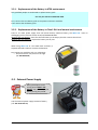
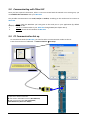
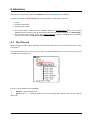
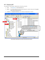
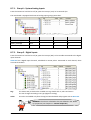
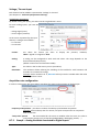
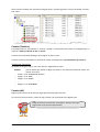
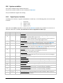
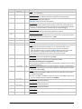
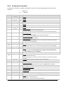
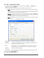
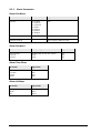
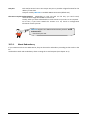
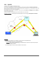
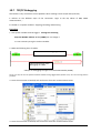
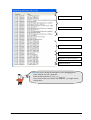
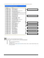
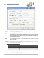
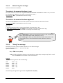
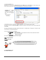
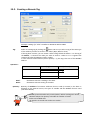
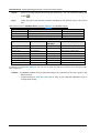
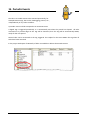
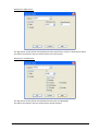
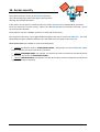
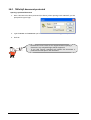
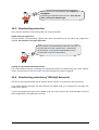
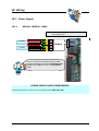
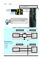
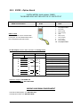
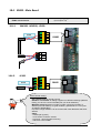
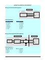
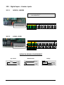
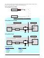
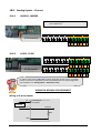
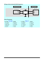
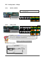
18.9. Analog Inputs – Voltage
18.9.1.
-WM100, -WM200
Connector:
Spring Cage Terminal block
(see chapter 3.9)
I/O Connector
Gnd PS U in I in
0
0
0
18.9.2.
PS U in I in
1
1
1
-LP400, -LP450
Gnd PS U in I in
2
2
2
PS U in I in
3
3
3
I/O Connector
Gnd PS U in I in
0
0
0
PS U in I in
1
1
1
In order to save energy, TBox ULP controls the power of the sensor. It activates
power on pin PS x at a frequency and a period defined in the Tag configuration
(see chapter 8.7.4. Analog Inputs – Acquisition rate).
WIRING IN NORMAL ENVIRONMENT
Wiring to 2-wires sensor
PS x
+
-
U in x
+12 (45mA) or
+24 (22mA)
Measure
SENSOR
GND
Version: 2.08
TBox - ULP
187