1
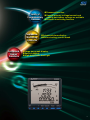
MITSUBISHI ELECTRONIC MULTI-MEASURING INSTRUMENT
MODEL
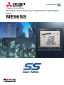
ME96SS
MITSUBISHI Electric Multi-Measuring Instrument SS Series
features high performance and crystal clear display.
With simple operating functions, SS Series is the best
support your measuring and monitoring systems.
Expand
Line-up
Enhanced
Measuring
Functions
»Improved Measuring
Accuracy
»Three model line-up
»High-spec class
»Standard class
»Economy class
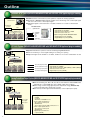
Contents
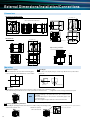
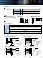
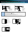
∑ Outline ··················································· 3
∑ External Dimensions/Installation/Connections ····· 25
∑ ME96 Super-S Series Features ················· 4
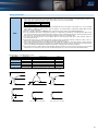
∑ Related Products ···································· 29
∑ Specifications ·········································· 9
∑ Safety Precautions ·································· 30
∑ Operating Instructions ····························· 13
1
»Password function
Variety of
»Special primary voltage/current and
Complementary special secondary voltage are settable
»Periodic monitoring function
Features
Impressive
Monitoring
Functions
Succeeded
Display
Functions
»Advanced alarm display
»Motor starting current mask
»Large bar-graph display
»Special display
»High-brightness backlight
2
Outline
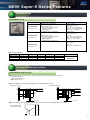
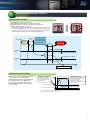
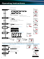
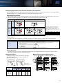
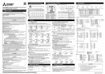
MODBUS® RTU System (ME96SSH-MB/ME96SSR-MB with ME-0052-SS96 (optional plug-in module))
»MODBUS® RTU communication system optimizes computer monitoring operations
»Attachment of ME-0052-SS96 (optional) enables remote monitoring of the contact input signal
and on/off control of the contact output signal
»Digital input signals can be latched for over 30ms, and there is no need for external latch
circuits
Central monitor
RS485/USB
converter
ME-0052-SS96
optional unit
USB
RS485 (MODBUS®RTU)
SHT(OFF)
CC(ON)
AL
PAL
TAL
ACB status
<MODBUS® RTU Interface Specifications>
• Max. Baud rate: 38.4kbps
• Max. Connection Distance: 1,200m
• Max. Connection Units: 31
<Optional Plug-in Module ME-0052-SS96>
• Digital Input: 5 points (24VDC)
• Digital Output: 2 points (35VDC)
CC-Link System (ME96SSH-MB/ME96SSR-MB with ME-0040C-SS96 (optional plug-in module))
»Optimum transmission system for remote monitoring using Mitsubishi PLC
»Remote monitoring of contact signal leading to less wiring, less spacing
»Digital unit signal can be latched for over 30ms, and there is no need for external latch circuits
CC-Link IE
MELSEC Series
CC-Link
Abnormal Signal (Facility)
Abnormal Signal (Earth Leakage)
Abnormal Signal (Temperature)
Circuit Breaker Status Signal, etc.
<CC-Link Interface>
• Max. Baud rate: 10Mbps
• Max. Connection Distance: 100m (10Mbps)~1,200m (156kbps)
• Max. Connection Units: 42
• Digital Input: 4 points (24VDC)
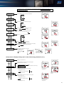
Analog/Pulse/Alarm Output System (ME96SSH-MB/ME96SSR-MB with ME-4210-SS96 (optional plug-in module))
»Remote monitoring of A, DA, V, W, var, VA, PF, Hz, Harmonics Current RMS value
and Harmonics voltage RMS value at 4 to 20mA output (max.4 outputs)
»Active energy, reactive energy,apparent power and periodic energy (ME96SSH-MB)
can be monitored by pulse output (max.of 2 pulse)
»Can remotely monitor upper/lower limit alarm by contact output (max.1 point)
CC-Link IE
Analog output
Pulse output
Alarm output
3
<Analog output specifications>
• 4-20mA
• 4 outputs
• Resistance load 600Ω or less
<Pulse output specifications>
• No-voltage a contact point
• 35VDC, 0.1A
• Select output from pulse widths of 0.125, 0.5 or 1s
<Alarm output specifications>
• No-voltage a contact point
• 35VDC, 0.1A
<Digital input specifications>
• 1 point (24VDC)
ME96 Super-S Series Features
Expand Line-up
Three Model Line-up
Model name
Transmission/Option specifications
Main measurement items
MODBUS® RTU communication
A, DA, V = ±0.1%
W, var, VA, Hz = ±0.2%
PF = 1.0%
Wh = class 0.5s (IEC 62053-22)
varh, Vah = class 2.0 (IEC 62053-23)
Harmonics = 31st-deg (max)
Rolling demand
Plug-in module (options)
• Analog/Pulse/Contact output/input
• CC-Link communication
• Digital input/output
(for MODBUS® RTU communication)
ME96SSH-MB
(High-spec class)
A, DA, V = ±0.2%
W, var, VA, Hz = ±0.5%
PF = 2.0%
Wh = class 1.0 (IEC 62053-21)
varh = class 2.0 (IEC 62053-23)
Harmonics = 13th-deg (max)
MODBUS® RTU communication
Plug-in module (options)
• Analog/Pulse/Contact output/input
• CC-Link communication
• Digital input/output
(for MODBUS® RTU communication)
ME96SSR-MB
(Standard class)
A, V = ±0.5%
W, Hz = ±0.5%
PF = 2.0%
Wh = class 1.0 (IEC 62053-21)
MODBUS® RTU communication
ME96SSE-MB
(Economy class)
Optional Plug-in Modules
Model name
Analog output
Pulse/Alarm output
Contact input
Contact output
Transmission function
ME-4210-SS96
4
2
1
—
—
ME-0040C-SS96
—
—
4
—
CC-Link
ME-0052-SS96
—
—
5
2
—
Used with
ME96SSH-MB
ME96SSR-MB
Note: Optional Plug-in Module can not be used with ME96SSE-MB.
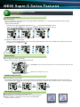
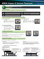
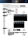
Enhanced Measuring Functions
Improved Measuring Accuracy
»Measuring accuracy of items such as current, voltage and active energy has been improved.
• current/voltage ±0.1%
• active energy class 0.5s
• Harmonics 1st to 31st
»Functions added for measuring Single phase 2-wire and Single phase 3-wire
Single phase 2-wire
Single phase 3-wire
1 2
K
L
1 0 2
k
l
U
V
u
v
+C1
T/R+
C1
T/R−
+C2
Ter
C2
T/R+
+C3
T/R−
C3
SLD
P1
SLD
MODBUS®RTU
Communication
k
l
K
L
k
l
+C1
T/R+
C1
T/R−
+C2
Ter
C2
T/R+
+C3
T/R−
C3
SLD
P1
SLD
MODBUS®RTU
Communication
MODBUS®RTU
Communication
P2
P2
P3
MA
P3
MA
PN
MB
PN
MB
Protective
Earthing
Protective
Earthing
Load
K
L
(+)
(−) Auxiliary power
Load
(+)
Auxiliary power
(−)
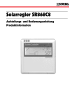
»Functions added for measuring Three phase 3-wire system star circuits and 400V direct connections
Three phase 3-wire
system (star circuit)
400V
400V
400V
4
ME96 Super-S Series Features
Succeeded Display Functions
Large Bar Graph Display
»Bar Graph Display
Each measuring items can be displayed by a bar graph. With bar graph display, one can grasps the rated value and percentage
against the alarm value instantly.
(1) Bar Graph Fixed Display
Measuring items can be displayed by bar graph. The
mark indicates that display is fixed.
Furthermore, the + and – buttons can be used to change the display between items measured.
Alarm indicator
Note: Alarm indicator blinks when it is set on alarm mode.
(2) Digital Values Display by Bar Graph
Values on the tri-level digital display can be shown by bar graphs (Except when the tri-level display is measuring the same items).
Bar graph shows the digital value of
Value shown by bar graph
Special Display
»Special Display by Display Pattern P00
Display can be selected as desired Display Pattern P00.
Upper/Middle/Lower levels: Select from A, DA, V, W, var, VA, PF, Hz, Wh, -Wh, varh, VAh
Maximum of four displays can be set
Max/Min Display Function
»Maximum/Minimum Value Display
The maximum and minimum value of each measuring items can be displayed. Since the max/min display shows the current value as
well as max/min values, the display can be used for monitoring. Also,range of minimum value to maximum value is shown by bar graph.
Alarm
indicator
High-brightness Backlight
»High-reliability and high-brightness backlight is built in
»Backlight brightness can be adjusted from level 1 to 5 (default setting is 3)
»“Always-on mode” or “Automatic off mode” can be selected (default
setting is automatic off mode)
ME96NS Series
5
ME96SS Series
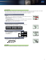
Impressive Monitoring Functions
Advanced Alarm Display
(1) Backlight blinks when an alarm occur.
(2) Automatic or manual alarm cancel can be selected.
(3) Upper/lower limits of up to four points can be monitored.
(4) Alarm output delay time can be set.
Time of alarm output after the maximum value and minimum value is reached can be
set. With this function,alarm output caused by frequency change at start-up current of
a motor and start-up of private power generating facility can be avided. Furthermore,
maximum value and minimum value do not update during alarm delay.
Current
Motor
starting
current
Alarm Delay
Time
No alarm output and
maximum/minimum
value update during
alarm delay time
Alarm Delay
time
Upper limit
value
Alarm
generation
Maximum Value Update
Minimum Value Update
Lower limit
value
Time
No lower limit alarm on 0A, 0V
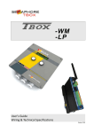
Motor Starting Current Mask
During motor current monitoring, this function
can be used to prevent updating the
maximum value and alarm output. Although
the maximum value is not updated, the
current value is displayed. The starting
current mask time can be set in the range
from 1s to 5min.
<Starting current detection>
The starting current mask
time starts when the current
exceeds the starting current
threshold value.
Starting current mask time
Current
value
Starting
current
<Starting current mask>
The maximum values for current and
power are not updated during the
starting current mask time.
Furthermore, the alarm is not
activated even if the upper limit alarm
value is exceeded.
Current upper limit alarm value
Starting current threshold value
Time
Note: Set the starting current threshold to a value lower than the lower limit value in consideration of
fluctuations in load current during operation.
6
ME96 Super-S Series Features
Variety of Complementary Features
Password Function
With the password function, the following items can be protected from an accidental execution.
No.
No.
Password-protected item
Password-protected item
shift to the setting mode
5
Adjust the time limit of rolling demand
2
Reset the max./min. values
6
Reset the peak value of rolling demand
3
Reset the value of active energy, reactive energy and apparent energy
7
Reset the value of operating time
4
Reset the value of periodic active energy
1
Special Primary Voltage/Current and Special Secondary Voltage are settable
(1) Special primary current
(2) Special primary voltage
1A~30kA
60V~75kV
Under 10A: Top two digits setting
Over 10A: Top three digits setting
Under 100V: Top two digits setting
Over 100V: Top three digits setting
(3) Special secondary voltage
Three phase 4-wire system
63.5, 100, 110, 115 and 120V
Three phase 3-wire, Single phase 2-wire system
100, 110 and 220V
Periodic Monitoring Function
Power consumption can be measured in two individual intervals (e.g., peak/offpeak, day/night, etc.).
The time segments can be switched according to the setting via communication
or the digital input (DI).
(The time segments cannot be switched manually (button operation).)
Power consumption
(period 1)
Power consumption
(period 2)
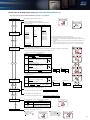
Rolling Demand Function
Rolling demand is the estimated power consumption in a specified period (interval).
There are two way calculation of rolling demand.
qRolling block
Use rolling block to set the interval and sub-intervals from
1~60min (1min intervals). Rolling demand is calculated and
updated at the end of each sub-interval.
wFixed block
Use fixed block to set the interval from 1~60min (1min
intervals). Rolling demand is calculated and updated at the
end of each interval. (For fixed block, use the same time
limits both of interval and sub-interval).
<Example: Interval, 15min; Sub-interval, 5min>
<Rolling demand calculation>
Rolling demand is calculated when
the sub-interval has been
completed.
<Example: Interval, 15min; Sub-interval, 15min>
15min
<Rolling demand display>
<Rolling demand calculation>
<Rolling demand display>
When an interval has been completed,
the rolling demand displayed is the
newest time limit value.
Rolling demand is calculated
when the sub-interval has been
completed.
When an interval has been completed,
the rolling demand displayed is the
newest time limit value.
15min
15min
5min
0
7
5
10
15
20
25
Time (min)
0
15
30
Time (min)
Test Function
»Even during a setup of a facility, where no current/voltage input is found, analog output, pulse output, alarm output, contact output,
and communication data is replied. This allows for checkup of wiring and monitoring program system.
*Depending on the optional unit and settings, the test function may not be available (may not be displayed).
(1) Communications Test
qDisplay
»The same as for the operating mode, display patterns and other data are shown as set.
»Both maximum and minimum values can be displayed.
wCommunication data
»Communication items and value are the same one on the display. The items value that are
not displayed is 0 (zero).
»Measuring items set for alarm will be displayed at the time of an alarm.
»Input/Output contact status can be monitored.
(2) Alarm/Contact Output Operation Test
qDisplays current alarm and contact status.
wPress the Reset button for 2sec, and regardless if there is an alarm or not,
the display and contact output will operate as follows.
Status
Display
Alarm
ON
Output terminal
Open
No alarm
OFF
Closed
(3) Analog Output Operation Test
qDisplay the output items.
wPress the + or - button to change the
analog output.
Note: Default value is 0%.
Output
0%
25%
50%
75%
100%
0%
25%
50%
75%
100%
Output specs
4-20mA
4mA
8mA
12mA
16mA
20mA
(4) Pulse Output Operation Test
Press the Reset button one time to output one pulse.
Note: After reaching 50, count will return to 1.
0 1 2 … 49 50[pulse]
Note: Default value is 0 pulses.
Standards
All products are compliant with CE Marking, UL Standards, KC mark and FCC/IC.
8
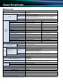
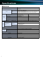
Specifications
■ME96SSH-MB
Model name
ME96SSH-MB
Phase wire
Three phase 4-wire, Three phase 3-wire (3CT, 2CT), Single phase 3-wire, Single phase 2-wire
(common use)
Rating
Current
5AAC, 1AAC (common use)
Voltage
Three phase 4-wire: 277/480VAC (max)
Three phase 3-wire: Delta connections: 220VAC (max), Star connections: 440VAC (max)
Single phase 3-wire: 220/440VAC (max)
Single phase 2-wire: Delta connections: 220VAC (max), Star connections: 440VAC)
Frequency
Measurement
items
and
accuracy
50-60Hz (common use)
Current (A)
A1, A2, A3, AN, AAVG
±0.1%
Current demand (DA)
DA1, DA2, DA3, DAN, DAAVG
±0.1%
Voltage (V)
V12, V23, V31, VAVG (L-L)
V1N, V2N, V3N, VAVG (L-N)
±0.1%
Active power (W)
W1, W2, W3, Σ W
±0.2%
Reactive power (var)
var1, var2, var3, Σ var
±0.2%
Apparent power (VA)
VA1, VA2, VA3, Σ VA
±0.2%
Power factor (PF)
PF1, PF2, PF3, Σ PF
±1.0%
Frequency (Hz)
Hz
±0.2%
Active energy (Wh)
Imported, Exported
class 0.5S
Reactive energy (varh)
Imported lead, lag
Exported lead, lag
class 2.0
class 2.0
Apparent energy (Vah)
ー
Harmonic current (HI)
1st to 31st degree (odd number degree only)
Harmonic voltage (HV)
1 to 31 degree (odd number degree only)
±2.0%
Rolling demand (DW)
Rolling block, fixed block
±0.2%
st
st
(IEC62053-22)
(IEC62053-23)
±2.0%
Periodic Active energy (Wh)
Periodic active energy 1, 2
class 0.5S
Operating time
Operating time 1, 2
(Reference)
Analog output response time
Measuring method
(IEC62053-22)
2s or less (except HI, HV. HI, HV: 10s or less)
Instantaneous value
A/V: RMS calculation, W/var/VA/Wh/varh/Vah: Digital multiplication, PF: Power ratio calculation,
Hz: Zero-cross, HI/HV:FFT
Demand value
DA: Thermal type calculation, DW: Rolling demand calculation
Type
LCD with backlight
6 digits each at upper, middle, and lower line
No. of display digits
Display and
segments
Digital display
Bar graph
Display updating time interval
Communication
Available optional plug-in module
Consumption
(VA)
A, DA, V, W, var, VA, PF: 4 digits DW, Hz: 3 digits
Wh, varh, VAh: 9 digits (6 or 12 possible)
Harmonic distortion ratio, content ratio: 3 digits Harmonic RMS: 4 digits
Operating time: 6 digits Contact input/output: I/O
21 segment bar graph, 22 segment indicator
0.5s or 1s (selectable)
MODBUS® RTU communication
ME-4210-SS96
ME-0040C-SS96
ME-0052-SS96
Power Failure Compensation
Non-volatile memory used (items: setting value, max/min value, active/reactive energy,
apparent energy, periodic active energy, rolling demand, operating time)
VT
Each phase 0.1VA (110VAC), 0.2VA (220VAC), 0.4VA (440VAC)
CT
Each phase 0.1VA (5AAC)
Auxiliary power circuit
Auxiliary power
Weight
Dimensions
Installation method
Operating temperature
Operating humidity
Storage temperature
Storage humidity
7VA (at 110VAC), 8VA (at 220VAC), 5W (at 100VDC)
100-240VAC (±15%), 100-240VDC (-30 +15%)
0.5kg
96×96×86 (H×W×D)
Embedded
-5~+55°C (average operating temperature: 35 or less per day)
0~85% RH (non condensing)
-25~+75°C (average temperature: 35 or less per day)
0~85% RH (non condensing)
Notes 1. Class values based on 100% of rated value.
Notes 2. Harmonic measurements where distortion ratio (content rate) is 100% or more may exceed ±2.0%.
Notes 3. Harmonic current cannot be measured without voltage input.
9
■ME96SSR-MB
Model name
ME96SSR-MB
Phase wire
Three phase 4-wire, Three phase 3-wire (3CT, 2CT), Single phase 3-wire, Single phase 2-wire
(common use)
Rating
Current
5AAC, 1AAC (common use)
Voltage
Three phase 4-wire: 277/480VAC (max)
Three phase 3-wire: Delta connections: 220VAC (max), Star connections: 440VAC (max)
Single phase 3-wire: 220/440VAC (max)
Single phase 2-wire: Delta connections: 220VAC (max), Star connections: 440VAC)
Frequency
Measurement
items
and
accuracy
50-60Hz (common use)
Current (A)
A1, A2, A3, AN, AAVG
±0.2%
Current demand (DA)
DA1, DA2, DA3, DAN, DAAVG
±0.2%
Voltage (V)
V12, V23, V31, VAVG (L-L)
V1N, V2N, V3N, VAVG (L-N)
±0.2%
Active power (W)
W1, W2, W3, Σ W
±0.5%
Reactive power (var)
var1, var2, var3, Σ var
±0.5%
Apparent power (VA)
VA1, VA2, VA3, Σ VA
±0.5%
Power factor (PF)
PF1, PF2, PF3, Σ PF
±2.0%
Frequency (Hz)
Hz
±0.5%
Active energy (Wh)
Imported, Exported
class 1.0
(IEC62053-21)
Reactive energy (varh)
Imported lead, lag
Exported lead, lag
class 2.0
(IEC62053-23)
ー
Apparent energy (Vah)
ー
Harmonic current (HI)
1st to 13th degree (odd number degree only)
Harmonic voltage (HV)
1 to 13 degree (odd number degree only)
±2.0%
Rolling demand (DW)
ー
ー
st
th
±2.0%
Periodic Active energy (Wh)
Periodic active energy 1, 2
class 1.0
Operating time
Operating time 1, 2
(Reference)
Analog output response time
2s or less (except HI, HV. HI, HV: 10s or less)
Measuring method
(IEC62053-21)
Instantaneous value
A/V: RMS calculation, W/var/VA/Wh/varh/Vah: Digital multiplication, PF: Power ratio calculation,
Hz: Zero-cross, HI/HV:FFT
Demand value
DA: Thermal type calculation
Type
LCD with backlight
6 digits each at upper, middle, and lower line
No. of display digits
Display and
segments
Digital display
Bar graph
Display updating time interval
Communication
Available optional plug-in module
Consumption
(VA)
A, DA, V, W, var, VA, PF: 4 digits Hz: 3 digits
Wh, varh: 9 digits (6 or 12 possible)
Harmonic distortion ratio, content ratio: 3 digits Harmonic RMS: 4 digits
Operating time: 6 digits Contact input/output: I/O
21 segment bar graph, 22 segment indicator
0.5s or 1s (selectable)
MODBUS® RTU communication
ME-4210-SS96
ME-0040C-SS96
ME-0052-SS96
Power Failure Compensation
Non-volatile memory used (items: setting value, max/min value, active/reactive energy,
periodic active energy, operating time)
VT
Each phase 0.1VA (110VAC), 0.2VA (220VAC), 0.4VA (440VAC)
CT
Each phase 0.1VA (5AAC)
Auxiliary power circuit
Auxiliary power
Weight
Dimensions
Installation method
Operating temperature
Operating humidity
Storage temperature
Storage humidity
7VA (at 110VAC), 8VA (at 220VAC), 5W (at 100VDC)
100-240VAC (±15%), 100-240VDC (-30 +15%)
0.5kg
96×96×86 (H×W×D)
Embedded
-5~+55°C (average operating temperature: 35 or less per day)
0~85% RH (non condensing)
-25~+75°C (average temperature: 35 or less per day)
0~85% RH (non condensing)
Notes 1. Class values based on 100% of rated value.
Notes 2. Harmonic measurements where distortion ratio (content rate) is 100% or more may exceed ±2.0%.
Notes 3. Harmonic current cannot be measured without voltage input.
10
Specifications
■ME96SSE-MB
Model name
ME96SSE-MB
Phase wire
Three phase 4-wire, Three phase 3-wire (3CT, 2CT), Single phase 3-wire, Single phase 2-wire
(common use)
Rating
Current
5AAC, 1AAC (common use)
Voltage
Three phase 4-wire: 277/480VAC (max)
Three phase 3-wire: Delta connections: 220VAC (max), Star connections: 440VAC (max)
Single phase 3-wire: 220/440VAC (max)
Single phase 2-wire: Delta connections: 220VAC (max), Star connections: 440VAC)
Frequency
Measurement
items
and
accuracy
50-60Hz (common use)
Current (A)
A1, A2, A3, AN, AAVG
±0.5%
Voltage (V)
V12, V23, V31, VAVG (L-L)
V1N, V2N, V3N, VAVG (L-N)
±0.5%
Active power (W)
W1, W2, W3, Σ W
±0.5%
Power factor (PF)
PF1, PF2, PF3, Σ PF
±2.0%
Frequency (Hz)
Hz
±0.5%
Active energy (Wh)
Imported
class 1.0 (IEC62053-21)
Operating time
Operating time 1, 2
(Reference)
Measuring method
Instantaneous value
Type
A/V: RMS calculation, W: Digital multiplication, PF: Power ratio calculation, Hz: Zero-cross
LCD with backlight
6 digits each at upper, middle, and lower line
No. of display digits
Display and
segments
Digital display
A, V, W, PF: 4 digits Hz: 3 digits
Wh: 9 digits (6 or 12 possible)
Operating time: 6 digits
Bar graph
21 segment bar graph, 22 segment indicator
Display updating time interval
Communication
Consumption
(VA)
MODBUS® RTU communication
Power Failure Compensation
Non-volatile memory used (items: setting value, max/min value, active energy, operating time)
VT
Each phase 0.1VA (110VAC), 0.2VA (220VAC), 0.4VA (440VAC)
CT
Each phase 0.1VA (5AAC)
Auxiliary power circuit
Auxiliary power
Weight
Dimensions
Installation method
Operating temperature
Operating humidity
Storage temperature
Storage humidity
Notes 1. Class values based on 100% of rated value.
11
0.5s or 1s (selectable)
7VA (at 110VAC), 8VA (at 220VAC), 5W (at 100VDC)
100-240VAC (±15%), 100-240VDC (-30 +15%)
0.5kg
96×96×86 (H×W×D)
Embedded
-5~+55°C (average operating temperature: 35 or less per day)
0~85% RH (non condensing)
-25~+75°C (average temperature: 35 or less per day)
0~85% RH (non condensing)
■Standards Compliance
Electromagnetic Compatibility
Emissions
EN61326-1/CISPR 11,
FCC Part15 Subpart B Class A
EN61326-1/CISPR 11
FCC Part15 Subpart B Class A
EN61000-3-2
EN61000-3-3
Radiated Emission
Conducted Emission
Harmonics Measurement
Flicker Meter Measurement
Immunity
Electrostatic discharge Immunity
Radio Frequency Electromagnetic field Immunity
Electrical Fast Transient/Burst Immunity
Surge Immunity
Conducted Disturbances、Induced By Radio Frequency Fields Immunity
Power Frequency Magnetic Field Immunity
Voltage Dips and Short Interruptions
Safety
Europe
U.S. and Canada
Installation Category
Measuring Category
Pollution Degree
EN61326-1/EN61000-4-2
EN61326-1/EN61000-4-3
EN61326-1/EN61000-4-4
EN61326-1/EN61000-4-5
EN61326-1/EN61000-4-6
EN61326-1/EN61000-4-8
EN61326-1/EN61000-4-11
CE、as per EN61010-1
cRUus as per UL61010-1、IEC61010-1
Ⅲ
Ⅲ
2
■Notes Regarding MODBUS® RTU Communication
Item
Interface
Protocol
Transmission method
Connection type
Baud rate
Data bit
Stop bit
Parity
Address
Distance
Max. connectable units
Terminal Resistance
Recommended Cable
Specifications
RS-485 2-wire half-duplex transmission
RTU mode
Asynchronous
Multi-point bus
2,400/4,800/9,600/19,200/38,400bps
8
1 or 2
Odd, even, none
1 to 255 (0:for broadcast mode)
1,200m (max)
31 units
120 Ω 1/2W
Shielded twisted-pair AWG24 to 14
■Notes Regarding CC-Link Communication
Item
No. of occupied stations
CC-Link version
Baud rate
Transmission method
Synchronous method
Encoding method
Transmission path format
Transmission format
Error control system
Number of connectable units
Remote station Number
Specifications
1 Station Remote device station
CC-Link Ver 1.10/Ver 2.00
10Mbps/5Mbps/2.5Mbps/625kbps/156kbps
Broadcast polling system
Frame synchronous system
NRZI
Bus format (EIA RS485)
HDLC
CRC (X16 + X12 + X5 + 1)
42 units (max, remote device station)
1 to 64
■ For CC-Link connection cables, please use the dedicated cables.
For information regarding dedicated cables, please refer to the CC-Link Partner Product Catalog published by the CC-Link Partner Association or CC-Link
Partner Product Information on the CC-Link Partner Association website (http://www.cc-link.org).
Notes 1.Dedicated CC-Link cables compatible with Ver. 1.00 cannot be used in tandem with dedicated CC-Link high-performance cables compatible
with Ver. 1.00.
Notes 2.In the case of systems consisting of units compatible with Ver. 1.00, 1.10 or 2.00 used in tandem with Ver. 1.00 or 1.10 cables, Ver. 1.00
specifications will apply for the maximum total cable length and length of cables between stations.
Notes 3.For terminal resistance, be sure to use 110 Ω ±5% (1/2W product) when using dedicated CC-Link cables or 130 Ω ±5% (1/2W product) when
using dedicated CC-Link high-performance cables.
■ Option Specifications
Item
Analog output
Pulse/Alarm output
Digital input
Digital output
Specification
4-20mA (0~600 Ω)
No-voltage “a” contact Capacity: 35VDC,
0.1A
19-30VDC 7mA or less
No-voltage a contact Capacity: 35VDC, 0.2A
Optional Plug-in Module type
ME-4210-SS96
ME-4210-SS96
ME-4210-SS96,ME-0040C-SS96,ME-0052-SS96
ME-0052-SS96
12
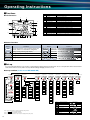
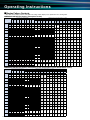
Operating Instructions
■Functions
»LCD Functions
1
2
3
3
4
6
4
5
7
9
8
NO.
1
2
3
4
5
6
7
8
9
10
11
12
13
14
15
16
Segment name
Lead Status
Lag status
Scale of the bar graph
Outside range
Alarm indicator
Bar graph status
Phase status
Digital
Unit
Metering status
Harmonics
Setup status
Test status
Clock status
Alarm status
Communication status
10
12
13 14
15
16
Description
Power factor status is lead
Power factor status is lag
The scale of the bar graph
Measurement value is outside range of scale of the bar graph
The setting value of the upper or lower limit
The item expressed with the bar graph
The phase for each of the digital displays
The measured value is displayed in a digital number
The unit for each of the digital display
When it is blinking, the instrument is counting active energy
The digital displays are harmonics values
Setup mode
Test mode
When it is blinking, the instrument is counting operating time
The upper or lower limit value was exceeded
The instrument is equipped with communication function
11
»Button Functions
Special functions
Basic functions
Button
Button
Functions
Set up setting items such as primary voltage and
SET
current, and choose and indicate setting itmes
DISPLAY
Push for 2s
Manual display change ⇔ Cyclic display change
PHASE
Push for 2s
Manual phase change ⇔ Cyclic phase change
+
Push for 2s
Zoom display of Wh, varh etc
Change setting and bar graph display
or
Change display from Max/Min to instantaneous value
MAX/MIN
PHASE
Change phase
DISPLAY
Change display
Functions
+ RESET
or
Push for 2s
Reset all the Max/Min values
Push for 1s
Fast forward or fast return values when setting
SET + RESET + PHASE
Reset Wh, varh, Vah values to zero by
hoiding down the buttons for 2 sec
■Set-up
For correct measurement, it is necessary to set the primary voltage/current in set-up mode. Access set-up mode from the measurement
mode and set the necessary items. Factory default settings will apply to items not set.
»Set-up workflow (in the case of ME96SSH-MB)
Set-up menu End
End
display
Set-up menu 1
Set-up menu 2
Phase/
Wire
Communication
type
Display
pattern
Cancel
display
Change/
Confirm
values set
Measurement screen
Enter
set-up
mode
Set-up menu 3
Set-up menu 4
Set-up menu 5
Set-up menu 6
Set-up menu 7
Set-up menu 8
Current
scale
Function
display
Upper/Lower
limit alarm
items
Analog
output 1
Time-based
power used
display
Operating
time display
Voltage
scale
Version
display
Upper/Lower
limit alarm
values
Analog
output 2
Time-based
power used
toggle setting
Operating
time count
target
Using VT/
direct input
MODBUS® RTU
address
CC-Link
station No.
Power
scale
Backlight
brightness
Alarm
mask time
Analog
output 3
Rolling
demand
display
Operating
time threshold
value
CT current
MODBUS® RTU
baud rate
CC-Link
baud rate
Reactive
power scale
Backlight
connection/
automatic
Alarm reset
method
Analog
output 4
Rolling demand
time limit
adjustment setting
Phase display
setting
Frequency
MODBUS® RTU
parity
CC-Link
version setting
Power factor
scale
Display
refresh time
Backlight
flashes at time
of alarm
Output
limit
Contact
input/output
display
IEC mode
setting
Rolling demand
time limit
MODBUS® RTU
stop bit
CC-Link
reset
Power used
scale
Motor starting
current mask
function
Harmonic
display
Pulse/Alarm
output function
Demand current
time limit
<When ME-0040C-SS96 is attached>
Enter setting value
confirmation mode
Pulse
output
Test mode
Contact
input reset
method
Symbol
Operation (function) details
Access set-up mode from operating mode
Access setting value confirmation
mode from operating mode
Button operation
SET + RESET
Press for 2s
SET
Press for 2s
SET
Save settings and return to operating mode
Notes 1. Basic measurements are possible by adjusting settings in menu 1
(
area enclosed by dotted line).
Notes 2. Item settings vary depending on the model.
Notes 3. Setting confirmation menu 9 (test mode) is not displayed in the setting mode.
13
Setting value confirmation menu 9
Select set-up menu
or
Move to next screen
SET
DISPLAY
Return to previous setting item
Skip remaining settings
Select cancel
SET
Press for 1s
or
●Basic
Set-up Operations
To access setting mode, press and hold the SET and RESET buttons down at the same time
for 2s. Press the SET button to display the items to be set, and the
and
buttons to set
the details. Settings can be saved for each set-up menu No. To do so, press the SET button
when the End screen is displayed.
The underlined setting parameter are
the initial value.
Set-up menu 1: Basic settings (set phase wire system, display pattern, Using VT/direct input, CT primary current, etc.)
Set-up menu
Adjust the set-up menu No. to “1”
qSet the phase/wire system according to the number
of measurement circuits targeted
SET
qPhase/Wire system
3-phase, 4-wire system
3-phase, 3-wire system (2CT)
3-phase, 3-wire system (3CT)
1-phase, 3-wire system (1N2 display)
1-phase, 3-wire system (1N3 display)
1-phase, 2-wire system
P01
P02
P03
P04
P05
P06
P07
P08
P09
P10
P11
P12
P13
P00
○
○
○
○
○
○
○
○
□
○
○
○
○
□
○
○
○
○
□
○
○
○
○
○
○
○
○
□
PF var VA Hz
○
○
○ ○ ○ ○
○ ○ ○ ○
○ ○ ○ ○
○
○
Vah
○
○
○
○
○
○
△
○
△
○
△
○
○
○
△
△
△
△
△
varh vah
△
○
△
△
○
△
○
○
○
□
○
□
○
□
○
□
○
□
○
○
○
□
□
○
□
○
□
△
△
△
△
△
△
△
△
△
△
△
△
△
△
DW HI/HV DI/DO
△ △ △
△ △ △
△ △ △
△ △ △
△ △ △
△ △ △
△ △ △
△ △ △
△ △ △
△ △ △
△ △ △
△ △ △
△ △ △
△ △ △
Operating time
○
○
○
○
○
○
○
○
□
W
○
○
○
○
○
△
△
△
△
△
△
△
△
△
△
△
△
△
△
○
○
○
○
○
○
○
○
□
○
○
○
○
□
○
○
○
○
○
○
○
○
□
W
○
○
○
○
○
PF var Hz
○
○
○ ○ ○
○ ○ ○
○ ○ ○
○
○
○
○
○
○
no
yES
・To set Three phase 3-wire or Single phase 2-wire
yES
△
○
△
○
△
○
○
○
△
△
△
△
△
varh
△
○
○
○
□
○
□
○
□
○
□
○
○
○
□
□
○
□
eSet VT
In the case of direct measurements (without VT) ⇒ To select no, press SET and see (1) below.
In the case of using VT ⇒ To select yes, press SET and see (2) below.
・To set Three phase 4-wire
○
△
△
△
△
△
△
△
△
△
△
△
△
△
△
△
△
DW
△
△
△
△
△
△
△
△
△
△
△
△
△
△
HI/HV DI/DO
△ △
△ △
△ △
△ △
△ △
△ △
△ △
△ △
△ △
△ △
△ △
△ △
△ △
△ △
Operating time
A DA V
○
○
○
○
○
○
○
○
Wh
(periodic)
Display pattern
Additional screens
P01
P02
P03
P04
P05
P06
P07
P08
P09
P10
P11
P12
P13
P00
SET
AN DA DAN V
○
○
○
○
○
○
○
○
(2) In the case of settings other than Three phase 4-wire (ME96SSH-MB)
SET
eVT/Direct voltage
A
○
○
○
○
Wh
(periodic)
Additional screens
Wh
(Imported)
Wh
(Exported)
wDisplay pattern
(1) In the case of Three phase 4-wire setting (ME96SSH-MB)
Wh
(Imported)
Wh
(Exported)
Varh
(Imported lag)
○: Can be displayed with this setting only
△: Other settings are required to display data
□: Select P00 and set display order and position
DISPLAY
w
SET
wSet the display pattern
DISPLAY
q
Wh
(Imported)
Wh
(Exported)
Varh
(Imported lag)
Wh
(Imported)
Wh
(Exported)
DISPLAY
3P4:
3P3, 2Ct:
3P3, 3Ct:
1P3, 1n2:
1P3, 1n3:
1P2:
Display pattern
DISPLAY
△
△
△
△
△
△
△
△
△
△
△
△
△
△
e
<For Single phase 3-wire setting for qPhase/Wire system >
Only used for direct measurements.
Skipped for this setting.
no
(1) In the case of direct measurements (without VT)
(a) Three phase 4-wire setting (phase voltage/line voltage)
63.5/110V 100/173V 110/190V 220/380V 240/415V 254/440V 277/480V
(b) Three phase 3-wire (2CT, 3CT) or Single phase 2-wire setting (line voltage)
e
(1)
110V 220V 440V
(c) Single phase 3-wire setting (1N2, 1N3) (phase voltage/line voltage)
110/220V 220/440V
14
Operating Instructions
<Continued from previous page>
e(2)
eVT/Direct voltage
(2) In the case of using with VT
<Secondary voltage settings>
(a) Three phase 4-wire setting (phase voltage)
63.5V
100V
110V
115V
120V
(b) Three phase 3-wire (2CT, 3CT) or Single phase 2-wire setting (line voltage)
100V
DISPLAY
110V
220V
SET
<Set primary voltage>
Can be set in 60~750,000V range (setting unit: V)
Factory default settings
Under 100V: Top two digits settings
Three phase 4-wire: 200V (phase voltage)
Over 100V:
Top three digits settings
Three phase 3-wire; Single phase 2-wire: 10,000V (line voltage)
rCT current
DISPLAY
SET
tFrequency
DISPLAY
SET
rSet CT
<Set secondary current>
1A 5A
<Set primary current>
Can be set in1.0~30,000.0A range (setting unit: A)
Factory default setting: 5.0A
Under 10A: Top two digits settings
Over 10A: Top three digits settings
⑤Set frequency
50Hz 60Hz
Notes1. Frequency scale on bar graph display will also change.
Notes2. Analog output scale will also change.
r
t
y
yRolling demand time
limit
ySet the rolling demand interval time limit (ME96SSH-MB only)
(1) Interval time limit
Setting range
1∼15∼60
(min)
DISPLAY
SET
uDemand current time
limit
(2) Sub-interval time limit
Setting range
1∼60
(min)
Setting interval
1min
uSet the demand current time limit (ME96SSH-MB, ME96SSR-MB only)
0s
10 s
20 s
30 s
SET
Set-up menu
Setting interval
1min
40 s
50 s
1 min
2 min
3 min
4 min
5 min
6 min
7 min
8 min
9 min
10 min
u
15 min
20 min
25 min
30 min
Select another set-up menu or finish set-up
‡To continue to set-up
Select the menu No.
using the
or
button.
‡To finish set-up
Press the
or
button
to display the End screen,
then press the SET button
to save the settings.
Set-up menu 2: Communication settings (MODBUS® RTU, CC-Link communication settings)
(CC-Link communication only possible when ME-0040C-SS96 is installed to ME96SSH-MB, ME96SSR-MB)
q
Set-up menu
Adjust the set-up menu No. to “2”
DISPLAY
qSelect CC-Link or MODBUS® RTU communication
SET
CC:
qSelect communication
system
DISPLAY
SET
CC-Link communication
Mb. rtu: MODBUS® RTU communication
wSet MODBUS® RTU communication address
If ME-0040C-SS96 (optional) is not installed, this
screen will not appear. In addition, when CC-Link
communication is selected, settings are
performed from y CC-Link station No.
w
Possible address settings: 1~255
wMODBUS® RTU
communication address
DISPLAY
15
SET
This screen will not be displayed if CC-Link
communication is selected using
qCommunication system selection.
• Set-up menu 2 screens e~t will not be displayed if CC-Link communication is selected using qCommunication system selection .
• Set-up menu 2 screens y~o will not be displayed if ME-0040C-SS96 (optional) is not attached or if CC-Link communication is selected using
qCommunication system selection .
e
eMODBUS® RTU
communication baud rate
DISPLAY
SET
rMODBUS® RTU
communication parity
DISPLAY
SET
tMODBUS® RTU
communication stop bit
DISPLAY
eSet the MODBUS® RTU communication baud rate.
2400bps
4800bps
9600bps
19.2kbps
38.4kbps
r
rSet the MODBUS® RTU communication parity.
non
odd
even
(EVEn)
SET
t
yCC-Link communication
station number
tSet the MODBUS® RTU communication stop bit.
Stop bit 1
Stop bit 2
y
ySet the CC-Link communication station number.
DISPLAY
SET
uCC-Link communication
speed
DISPLAY
SET
iSet CC-Link
communication version
DISPLAY
SET
oReset communication
Possible station number settings: 1~64
u
uSet the CC-Link communication speed.
156kbps
625kbps
2.5Mbps
5Mbps
10Mbps
i
iSet the CC-Link communication version.
Version 1.10
Version 2.00
o
oSet to “on” if changes have been made to the CC-Link settings
(if not set to “on,” changes will not be effective).
oFF on
SET
Set-up menu
Select another set-up menu or end set-up
■To continue to set-up
Select the menu
number using the
or
button.
■To finish set-up
Press the
or
button
to display the End screen,
and then press the SET
button to save settings.
Set-up menu 3: Display settings (max. scale, active energy, harmonics, etc.)
Set-up menu
Change to set-up menu No. 3.
q(1)
DISPLAY
SET
qCurrent scale
qSet the maximum current scale value on the bar graph
(1) Maximum current scale value
CT primary current value
Set-up menu 1.4.1
primary current setting
Set value
SP.
(special primary current value)
(2) Maximum current scale value special setting
DISPLAY
SET
+3 steps (approx. 120%)
q(2)
This screen will not
appear if the current is
not selected in the
display pattern.
±0 steps (100%: instrument rating)
wVoltage scale
-10 steps (approx. 40%)
w
This screen will not appear if “CT
primary current value” is
selected.
wSet the maximum voltage scale value on the bar graph
Maximum scale value
DISPLAY
SET
+10 steps (approx. 250%)
±0 steps (100%: instrument rating)
-18 steps (approx. 20%)
This screen will not
appear if the voltage is
not selected in the
display pattern.
16
Operating Instructions
e(1)
ePower scale
eSet the maximum power/rolling demand scale value on the bar graph, and select positive-only scale
or positive/negative scale (rolling demand is only for ME96SSH-MB).
(1) Maximum scale value
+3 steps (approx. 120%)
±0 steps (100%: instrument rating)
DISPLAY
SET
DISPLAY
−18 steps (approx. 20%)
SET
(2) Positive-only or Positive/Negative
Positive-only
rReactive power scale
DISPLAY
SET
Positive/Negative
rSet the maximum reactive power scale value on the bar graph (ME96SSH-MB, ME96SSR-MB only).
r
The setting procedure is the same as that described in
ePower unit (1) Max. scale value.
The reactive power scale can only be positive/negative.
This screen will not
appear if the power is
not selected in the
display pattern.
t
tPower factor scale
tSet the power factor scale on the bar graph.
DISPLAY
SET
yMeasure power consumption
−0.5~1~0.5
−0~1~0
ySet display combinations of receiving/transmitting, lag/lead, power
used/reactive power used and the measurement method for reactive
power used (ME96SSH-MB, ME96SSR-MB only).
Combinations
(set value)
Display combinations
Varh
Imported
Exported
Imported Exported
Lag
Lead
Lag
Lead
Wh
I
II
III
IV
This screen will not appear if
the reactive power is not
selected in the display
pattern.
Reactive energy
used measurement
method
2 Quadrants Measurement
4 Quadrants Measurement
Combinations I, II ⇒
DISPLAY
SET
Suitable for measuring reactive power in facilities not equipped with in-house generators, and generally for capacitor loads
where the power factor is close to zero.
Combinations III, IV ⇒ Suitable for measurements in facilities equipped with in-house generators.
<Example display screens>
Combination I
Combination II
: Imported
uHarmonic display
Set-up menu
: varh lag
on
(with)
When the display is set to “on,” the harmonic value measured will be
displayed on an additional screen.
Select another set-up menu or end set-up
‡To continue to set-up
Select the menu
number using the
or
button.
17
: varh lead
Combination IV
uSelect with or without harmonic display (ME96SSH-MB, ME96SSR-MB only).
oFF
(without)
SET
: Exported
Combination III
‡To finish set-up
Press the
or
button
to display the End screen,
and then press the SET
button to save settings.
u
Set-up menu 6: Analog output setting (ME96SSH-MB, ME96SSR-MB only)
This menu will not appear if ME-4210-SS96 (optional) is not installed.
Set-up menu
Adjust settings to match set-up menu No. 6.
q
qSet the output items for “analog output CH1.”
Select the measured items to be output from the table below.
Three phase 4-wire
DISPLAY
SET
qAnalog output CH1
output items
DISPLAY
SET
wAnalog output CH1
detailed settings
non
A1
A2
A3
AN
AAVG (CH1)
Demand A1
Demand A2
Demand A3
Demand AN
Demand AAVG
V1N
V2N
V3N
VAVG (L-N) (CH2)
Three phase 4-wire
V12
V23
V31
VAVG (L-L)
W1
W2
W3
W∑ (CH3)
var1
var2
var3
var∑
VA1
VA2
VA3
VA∑
PF1
PF2
PF3
PF∑ (CH4)
Hz
Harmonic A1
Harmonic A2
Harmonic A3
Harmonic AN
Harmonic V1N
Harmonic V2N
Harmonic V3N
Notes 1. The same measurement items can be set for all channels.
Notes 2. Measurement items not included in the selected display pattern can also be chosen.
Notes 3. Channels set to “non” will have minimum output (4mA). Additionally, set-up will proceed to the
next channel.
Notes 4. Underlined specifications are factory default settings of measurement items allocated to each
channel.
Notes 5. Harmonic current is output at the scale of 0~60% (with respect to rated value) of the total
effective value. Harmonic voltage is output at the scale of 0~20% of the total distortion ratio.
AVG: Average value, Σ: Total effective value
w(1)
wSet the details for “analog output CH1.”
(The following settings can be made separately from the measurement items included in the display pattern.)
(1) If analog output is selected for current, demand current, voltage, power,
reactive power, power factor (set-up menu: 6.1.1)
Output item
Setting range
CT primary current value (value set for set-up menu 1.4.1 primary current setting )
A
Demand A
SP. (special primary current value)
+10 steps (approx. 250%)
±0 steps (100%: standard max. scale value)
V
DISPLAY
−18 steps (approx. 20%)
SET
+3 steps (approx. 120%)
W
var
DISPLAY
±0 steps (100%: instrument rating)
mA
−18 steps (approx. 20%)
−0.5~1~0.5
PF
SET
w(2)
mA
20
12
4
−0~1~0
-0.5
20
12
4
1
0.5
-0
1
0
(2) If analog output is selected for current, demand current, power
(set-up menu: 6.1.2)
Output item
Setting range
+3 steps (approx. 120%)
eAnalog output CH2~4
output items
A
Demand A
±0 steps (100%: instrument rating)
−10 steps (approx. 40%)
DISPLAY
SET
rAnalog output CH2~4
detailed settings
W
Positive-only
<Positive-only>
mA
<Positive/Negative>
mA
20
12
4
20
Positive/Negative
4
0
40kW
-40kW
DISPLAY
0
40kW
SET
To next channel settings
eSet the output items for “analog output CH2~4.”
The setting procedure is the same as that of qAnalog output CH1 output items .
rSet the details for “analog output CH2~4.”
DISPLAY
SET
The setting procedure is the same as that of wAnalog output CH1 detailed settings .
tAnalog output limit
SET
t
tSet the upper limit for analog output (same for all channels)
Setting
oFF
(no limit)
on
(limit)
Explanation
Output to +5% of upper limit and -5% of
lower limit (with respect to span value)
Output to +1% of upper limit and -1% of
lower limit (with respect to span value)
Note: Skip this setting when the analog output of all channel output items is set to “non.”
Set-up menu
Select another set-up menu or end set-up
‡To continue to set-up
Select the menu
number using the
or
button.
‡To finish set-up
Press the
or
button
to display the End screen,
and then press the SET
button to save settings.
18
Operating Instructions
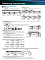
‡Operation (for ME96SSH-MB)
»Changing Phases
»Display Change
Press DISPLAY , the measurement display switches over.
Press PHASE , the current phase and the voltage phase switches over.
Example of changing display (Three phase 4-wire system; display pattern: P01; no additional screens)
Example of changing phases (Three phase 4-wire system)
DISPLAY
PHASE
DISPLAY
<Screen 1 of 4>
Upper: Current
Middle: Power
Lower: Voltage
DISPLAY
<Screen 2 of 4>
Upper: Current
Middle: Power
Lower: Power factor
PHASE
<Screen 4 of 4>
Upper: Current
Middle: No display
Lower: N-phase current
<Screen 3 of 4>
Upper: Current
Middle: Power factor
Lower: Voltage
Current phase 1
Power phase 1
Voltage phase 1N
Average current
Power (total)
Average voltage (interphase)
Current phase 2
Power phase 2
Voltage phase 2N
Current phase 3
Power phase 3
Voltage phase 3N
PHASE
PHASE
PHASE
Current phase 3
Power phase 3
Voltage phase 31
»Bar
PHASE
DISPLAY
PHASE
Current phase 2
Power phase 2
Voltage phase 23
PHASE
Current phase 1
Power phase 1
Voltage phase 12
Average current
Power (total)
Average voltage
(between lines)
Graph Display
Items measured can be displayed on the bar graph. By displaying one item by a bar graph and other three items by digital numbers
four elements can be displayed at once.
• Bar graph explanation
The or
mark indicates that the measurement item is displayed on the bar graph.
• Select bar graph
Press the
or
button to select the measurement items to be displayed on the bar graph.
Three phase 4-wire system
(Upper)
VAVG(LN)
(Middle)
(Lower)
(clockwise)
(anticlockwise)
VAVG(LL)
AAVG
∑W
Hz
∑PF
∑var
Example of bottom item
displayed in the bar graph
»Maximum/Minimum Display Values
Press the MAX/MIN button to change to the maximum and minimum values
of the display screen. Press it again to return to the current value display screen.
»Reset
Example of power factor
displayed in the bar graph
Example of switching between changing current value
display and maximum/minimum value display screens
Maximum/Minimum Values
MAX/MIN
Press the RESET button for 2s to reset the maximum/minimum values of
the measurement items displayed. The maximum/minimum values will
become the current values.
Current value display screen
Press the RESET and
buttons simultaneously for 2s to reset all
maximum/minimum values. The maximum/minimum values will become the current values.
Maximum/Minimum value
display screen
»Displaying Active energy/Reactive energy/Apparent energy
* To display these screens,
it is necessary to change
the power used measurement
settings using set-up menu 3.
Active energy (Imported)
Active energy (Exported)*
Apparent energy
Reactive energy
(Imported,lag)
Reactive energy
(Imported,lead)*
Reactive energy
(Exported,lag)*
Reactive energy
(Exported,lead)*
Change the unit (M, k, none) or increase the digits in the bottom display for power used/reactive power used/apparent power
used/time-based power used to check the lower/higher-order digits. Push the
and
buttons simultaneously for 2s to switch
between screens.
Power used (receiving): Example of changing 012,345,678,901,234.567Wh
Press
Unit: M
»Reset
19
and
for 2s
Bottom digits increased
Unit: None
Unit: k
Active energy/Reactive energy/Apparent energy
Press the SET , RESET and PHASE buttons simultaneously for 2s to reset all of the following together:
active energy/reactive energy/apparent energy (this operation only works on the current value display screen).
»Changing Upper/Lower Limits for Alarm Activation and Cancellation
When measurement values exceed the upper/lower limit values that have been set, an alarm activates and the screen begins to blink.
The blinking mark on the bar graph indicates the current upper/lower limit value settings.
»During
Alarm Generation
Alarm condition: When a measured value exceeds the alarm value setting, the screen begins to flash and the alarm contact closes.
Alarm cancelled: When the alarm is cancelled, the screen stops flashing and the alarm contact opens.
Alarm reset method
Measurement value ≥ Upper limit alarm value
(or ≤ Lower limit alarm value)
or
Measurement value < Upper limit alarm value
(or > Lower limit alarm value)
Constantly on
will flash
Upper/Lower limit indicator
Screen
Automatic
(Auto)
Alarm contact
or
If the item that caused the alarm is displayed on
the screen, the digital value, unit (A, V, W, var,
PF, HZ, %, DM, THD) and phase (1, 2, 3, N) will
be displayed as shown in the table below. If the
item is not displayed on the screen, the screen will
not flash.
Open
Closed
will flash
or
Constantly on
will flash
RESET
Screen
Manual
(Hold)
(Alarm activated)
(Alarm on hold)
Closed
Closed
Alarm contact
»Alarm
(Alarm cancelled)
Open
Phase
Alarm status Digital value
Unit
Alarm activated Flashing* Flashing Flashing*
Alarm on hold
Flashing Flashing*
On
Alarm cancelled
On
On
On
* Only flashes if the phase that caused the alarm is being displayed.
Cancel
The alarm can be reset automatically or manually. The alarm recovery method varies according to the reset method setting.
Automatic (Auto)
The alarm resets automatically when the measurement value returns to within the upper/lower limit set value.
The alarm setting changes to “on hold” even after the measurement value becomes returns to within the upper/lower limit value setting. Once the
value returns to within the upper/lower limit value set, perform the following alarm recovery operations.
(Note: Alarm recovery operations cannot be carried out from the maximum/minimum value display screen or contact input screen.)
<To select item and cancel alarm>
When the item that caused the alarm is displayed, press the RESET button to deactivate the alarm.
For items with phases such as current and voltage, it is necessary to
press the RESET button for each phase to cancel the alarm.
<To cancel alarms for all items>
To cancel alarms for all items at once (batch), press the RESET button for 2s when in operating mode.
Manual (Hold)
»Alarm
delay Time
If an alarm delay time has been set, alarm notification begins only when the measurement value exceeds the upper/lower limit
alarm value for a period longer than the alarm delay time.
»Harmonic Display
»Changing the Harmonic Degree Display
The harmonic effective value, distortion ratio and content
ratio can be displayed. To do so, first set the harmonic
display (set-up menu: 3.7).
<Example of total harmonic current display>
<Example of 5th-deg harmonic voltage display>
Press the
or
button to change the harmonic degree.
Harmonic current
N-phase harmonic current
Harmonic voltage
Current total phase N
Voltage total phase 1N
PHASE
Previous
measurement
screen
PHASE
Voltage total phase 1
Voltage total phases 2, 3
DISPLAY
Voltage total phases 2N, 3N
DISPLAY
Current 1st-degree phase 1
DISPLAY
Current 1st-degree phase N
Current 1 -degree phases 2, 3
Upper: Degree No.
Middle: Distortion (content) ratio
Lower: Effective value
Degree
Harmonic total
1st (fundamental)
3rd, 5th, 7th, 9th,
11th, 13th, 15th,
17th, 19th, 21st,
23rd, 25th, 27th,
29th ane 31st
Harmonic current N-phase harmonic current
Distortion
Distortion
RMS
RMS
(content) ratio
(content) ratio
Harmonic voltage
Distortion
RMS
(content) ratio
○
○
○
―
○
○
―
―
○
○
○
―
○
○
○
―
○
○
Displayed in order: 3rd,
5th, 7th, 9th, 11th, 13th,
15th, 17th, 19th, 21st,
23rd, 25th, 27th, 29th
Current 31st-degree phase 1
Current 31st-degree phases 2, 3
DISPLAY
Voltage 1st-degree, phase 1N
Voltage 1 -degree, phases 2N, 3N
st
st
Displayed in order: 3rd,
5th, 7th, 9th, 11th, 13th,
15th, 17th, 19th, 21st,
23rd, 25th, 27th, 29th
Current 31st-degree phase N
Displayed in order: 3rd,
5th, 7th, 9th, 11th, 13th,
15th, 17th, 19th, 21st,
23rd, 25th, 27th, 29th
Next
measurement
screen
Voltage 31st-degree, phase N
Voltage 31st-degree, phases 2N, 3N
20
Operating Instructions
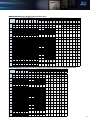
■Display Pattern Contents
The items set in display patterns and additional settings will be displayed as explained in the following table.
»ME96SSH-MB Screen Display (Three phase 4-wire)
Screen set based on display pattern
Display pattern
P01
P02
P03
P04
P05
P06
P07
P08
P09
P10
P11
P12
P13
P00
No.1
No.2
No.3
No.4
No.5
No.6
No.7
Additional screens (set in set-up menu Nos. 3, 7 and 8)
No.8
No.9
No.10
No.11
No.12
Wh
Wh
exported
varh
No.13
No.14
No.15
No.16
No.17
No.18
VAh
Periodic
active
energy
Wh1
Periodic
active
energy
Wh2
varh
varh
varh
Imported exported exported
(lead)
(lag)
(lead)
Upper
A
A
A
A
-
-
Middle
W
W
PF
-
Periodic
active
energy
Wh1
Periodic
active
energy
Wh2
Lower
V
PF
V
AN
Upper
Middle
Lower
Upper
Middle
Lower
Upper
A
V
Wh
A
PF
V
A
A
W
Wh
A
PF
W
A
A
PF
Wh
A
PF
var
A
A
-
AN
A
PF
VA
A
A
PF
Hz
A
A
-
AN
A
A
Middle
V
W
var
VA
PF
Hz
-
Lower
Wh
Wh
varh
VAh
Wh
Wh
AN
Upper
Middle
Lower
Upper
Middle
Lower
Upper
Middle
Lower
Upper
Middle
Lower
Upper
Middle
Lower
Upper
Middle
Lower
Upper
Middle
Lower
Upper
Middle
Lower
Upper
PF
W
var
A1
A2
A3
A
V
W
A
V
Wh
A
DA
V
A
DA
V
A
DA
Wh
A
DA
Wh
A1
Hz
W
var
V1N
V2N
V3N
A1
A2
A3
A
W
Wh
A1
A2
A3
A
DA
W
A
V
Wh
A
W
Wh
V1N
VA
W
var
A
-
V
V1N
V2N
V3N
A1
A2
A3
DA1
DA2
DA3
A1
A2
A3
DA1
DA2
DA3
A
V
Wh
W1
A
-
AN
A
-
AN
V1N
V2N
V3N
V1N
V2N
V3N
DA1
DA2
DA3
V1N
V2N
V3N
DA
V
Wh
var1
A
-
AN
A
-
AN
V1N
V2N
V3N
A
-
AN
W
V
Wh
VA1
DA
-
DAN
A
-
AN
DA
-
DAN
A
-
AN
PF 1
DA
-
DAN
V
V
A
Middle
A2
V2N
W2
var2
VA2
PF 2
Hz
Hz
AN
Lower
A3
V3N
W3
var3
VA3
PF 3
Wh
varh
VAh
-
Wh
-
Wh
exported
No.19
No.20
No.21
No.22
No.23
Harmonic
Rolling Harmonic
Harmonic DI
current
demand current
voltage status
N-phase
Degree No. Degree No. Degree No.
DI
-
Distortion
-
Distortion
(content) ratio
RMS
RMS
RMS
Peak value (content) ratio
Demand
value
P03
P04
P05
P06
P07
P08
P09
P10
P11
P12
P13
P00
21
No.26
-
-
hour2
Contact Contact Operating Operating
status status
time
time
Same Same Same Same Same Same Same Same Same Same
as
as
as
as
as
as
as
as
as
as
above above above above above above above above above above
Same Same Same Same Same Same Same Same Same Same
as
as
as
as
as
as
as
as
as
as
above above above above above above above above above above
-
-
-
Wh
Wh
exported
varh
-
-
-
varh
varh
varh
Imported exported exported
(lead)
(lag)
(lead)
-
VAh
Same Same Same Same Same Same Same Same Same Same
as
as
as
as
as
as
as
as
as
as
above above above above above above above above above above
Upper
Free
Free
Free
Free
Free
Free
Free
Free
Lower
Free
Free
Free
Free
Same Same Same Same Same Same Same Same Same Same
as
as
as
as
as
as
as
as
as
as
above above above above above above above above above above
Same Same Same Same Same Same Same Same Same Same
as
as
as
as
as
as
as
as
as
as
above above above above above above above above above above
-
Wh
-
Wh
exported
Same Same Same Same Same Same Same Same Same Same
as
as
as
as
as
as
as
as
as
as
above above above above above above above above above above
Same Same Same Same Same Same Same Same Same Same
as
as
as
as
as
as
as
as
as
as
above above above above above above above above above above
DA
-
DAN
Same Same Same Same Same Same Same Same Same Same
as
as
as
as
as
as
as
as
as
as
above above above above above above above above above above
-
Wh
-
Wh
Screen set based on display pattern
P02
DO
DI No. DO No. hour1
-
Wh
-
Wh
exported
-
Wh
exported
-
Wh
exported
Same Same Same Same Same Same Same Same Same Same
as
as
as
as
as
as
as
as
as
as
above above above above above above above above above above
Same Same Same Same Same Same Same Same Same Same
as
as
as
as
as
as
as
as
as
as
above above above above above above above above above above
-
varh
-
-
-
Wh
Wh
exported
varh
-
-
-
varh
varh
varh
Imported exported exported
(lead)
(lag)
(lead)
-
-
-
varh
varh
varh
Imported exported exported
(lead)
(lag)
(lead)
-
VAh
-
VAh
Same Same Same Same Same Same Same Same Same Same
as
as
as
as
as
as
as
as
as
as
above above above above above above above above above above
Same Same Same Same Same Same Same Same Same Same
as
as
as
as
as
as
as
as
as
as
above above above above above above above above above above
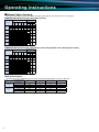
»ME96SSH-MB Screen Display (Three phase 3-wire, Single phase 3-wire, Single phase 2-wire)
P01
No.25
DO Operating Operating
status time 1
time 2
Same Same Same Same Same Same Same Same Same Same
as
as
as
as
as
as
as
as
as
as
above above above above above above above above above above
Middle
Display pattern
No.24
No.4
No.5
Additional screens (set in set-up menu Nos. 3, 7 and 8)
No.6
No.7
Wh
Wh
exported
No.8
No.9
No.10
No.11
varh
varh
varh
Imported exported exported
(lead)
(lag)
(lead)
No.12
No.13
Periodic
active
energy
Wh1
Periodic
active
energy
Wh2
No.1
No.2
No.3
Upper
A
A
A
-
-
Middle
W
W
PF
Lower
V
PF
V
Periodic
active
energy
Wh1
Periodic
active
energy
Wh2
Upper
Middle
Lower
Upper
Middle
Lower
Upper
A
V
Wh
A
PF
V
A
A
W
Wh
A
PF
W
A
A
PF
Wh
A
PF
var
A
A
PF
Hz
A
A
Middle
V
W
var
PF
Hz
varh
Wh
Wh
-
Wh
varh
-
Wh
exported
No.14
No.15
No.16
No.17
Rolling Harmonic Harmonic DI
demand current voltage status
-
Degree No. Degree No.
Distortion
Distortion
RMS
RMS
DI
No.18
No.19
DO
-
Peak value (content) ratio (content) ratio DI No. DO No. hour1
Demand
value
No.20
DO Operating Operating
status time 1
time 2
-
hour2
Contact Contact Operating Operating
time
time
status status
Same Same Same Same Same Same Same Same Same
as
as
as
as
as
as
as
as
as
above above above above above above above above above
Same Same Same Same Same Same Same Same Same
as
as
as
as
as
as
as
as
as
above above above above above above above above above
Lower
Wh
Wh
Upper
Middle
Lower
Upper
Middle
Lower
Upper
Middle
Lower
Upper
Middle
Lower
Upper
Middle
Lower
Upper
Middle
Lower
Upper
Middle
Lower
Upper
Middle
Lower
Upper
PF
W
var
A1
A2
A3
A
V
W
A
V
Wh
A
DA
V
A
DA
V
A
DA
Wh
A
DA
Wh
A1
Hz
W
var
V12
V23
V31
A1
A2
A3
A
W
Wh
A1
A2
A3
A
DA
W
A
V
Wh
A
W
Wh
V12
A
-
V
V12
V23
V31
A1
A2
A3
DA1
DA2
DA3
A1
A2
A3
DA1
DA2
DA3
A
V
Wh
W
V12
V23
V31
V12
V23
V31
DA1
DA2
DA3
V12
V23
V31
DA
V
Wh
V
Middle
A2
V23
var
Hz
Hz
varh
-
-
-
Wh
Wh
exported
varh
-
-
-
Same Same Same Same Same Same Same Same Same
varh
varh
varh
as
as
as
as
as
as
as
as
as
Imported exported exported above above above above above above above above above
(lead)
(lag)
(lead)
Same Same Same Same Same Same Same Same Same
as
as
as
as
as
as
as
as
as
above above above above above above above above above
Same Same Same Same Same Same Same Same Same
as
as
as
as
as
as
as
as
as
above above above above above above above above above
Same Same Same Same Same Same Same Same Same
as
as
as
as
as
as
as
as
as
above above above above above above above above above
Lower
A3
V31
PF
Wh
Upper
Free
Free
Free
Free
Middle
Free
Free
Free
Free
Lower
Free
Free
Free
Free
-
Wh
-
Wh
exported
Same Same Same Same Same Same Same Same Same
as
as
as
as
as
as
as
as
as
above above above above above above above above above
Same Same Same Same Same Same Same Same Same
as
as
as
as
as
as
as
as
as
above above above above above above above above above
V12
V23
V31
Same Same Same Same Same Same Same Same Same
as
as
as
as
as
as
as
as
as
above above above above above above above above above
-
Wh
W
V
Wh
V
-
Wh
-
Wh
-
Wh
exported
-
Wh
exported
-
Wh
exported
Same Same Same Same Same Same Same Same Same
as
as
as
as
as
as
as
as
as
above above above above above above above above above
Same Same Same Same Same Same Same Same Same
as
as
as
as
as
as
as
as
as
above above above above above above above above above
-
varh
-
-
-
Wh
Wh
exported
varh
-
-
-
Same Same Same Same Same Same Same Same Same
varh
varh
varh
as
as
as
as
as
as
as
as
as
Imported exported exported above above above above above above above above above
(lead)
(lag)
(lead)
-
-
-
Same Same Same Same Same Same Same Same Same
varh
varh
varh
as
as
as
as
as
as
as
as
as
Imported exported exported above above above above above above above above above
(lead)
(lag)
(lead)
»ME96SSR-MB Screen Display (Three phase 4-wire)
Screen set based on display pattern
Display pattern
P01
P02
P03
P04
P05
P06
P07
P08
P09
P10
P11
P12
P13
P00
No.1
No.2
No.3
No.4
No.5
No.6
No.7
Additional screens (set in set-up menu Nos. 3, 7 and 8)
No.8
No.9
No.10
No.11
No.12
Wh
Wh
exported
varh
No.13
No.14
No.15
No.16
No.17
varh
varh
varh
Imported exported exported
(lead)
(lag)
(lead)
Periodic
active
energy
Wh1
Periodic
active
energy
Wh2
Upper
A
A
A
A
-
Middle
W
W
PF
-
Periodic
active
energy
Wh1
Lower
V
PF
V
AN
Upper
Middle
Lower
Upper
Middle
Lower
Upper
A
V
Wh
A
PF
V
A
A
W
Wh
A
PF
W
A
A
PF
Wh
A
PF
var
A
A
-
AN
A
PF
VA
A
A
PF
Hz
A
A
-
AN
A
A
Middle
V
W
var
VA
PF
Hz
-
Lower
Wh
Wh
varh
VAh
Wh
Wh
AN
Upper
Middle
Lower
Upper
Middle
Lower
Upper
Middle
Lower
Upper
Middle
Lower
Upper
Middle
Lower
Upper
Middle
Lower
Upper
Middle
Lower
Upper
Middle
Lower
Upper
PF
W
var
A1
A2
A3
A
V
W
A
V
Wh
A
DA
V
A
DA
V
A
DA
Wh
A
DA
Wh
A1
Hz
W
var
V1N
V2N
V3N
A1
A2
A3
A
W
Wh
A1
A2
A3
A
DA
W
A
V
Wh
A
W
Wh
V1N
VA
W
var
A
-
V
V1N
V2N
V3N
A1
A2
A3
DA1
DA2
DA3
A1
A2
A3
DA1
DA2
DA3
A
V
Wh
W1
A
-
AN
A
-
AN
V1N
V2N
V3N
V1N
V2N
V3N
DA1
DA2
DA3
V1N
V2N
V3N
DA
V
Wh
var1
A
-
AN
A
-
AN
V1N
V2N
V3N
A
-
AN
W
V
Wh
VA1
DA
-
DAN
A
-
AN
DA
-
DAN
A
-
AN
PF 1
DA
-
DAN
V
V
A
Middle
A2
V2N
W2
var2
VA2
PF 2
Hz
Hz
-
VA3
PF 3
Wh
varh
AN
-
Wh
-
Wh
exported
-
No.18
No.19
No.20
No.21
Harmonic
Harmonic
Harmonic DI
current
current
voltage status
N-phase
Degree No. Degree No. Degree No.
DI
Periodic Distortion
active (content) ratio
energy
RMS
Wh2
-
Distortion
(content) ratio
RMS
RMS
No.22
No.23
No.24
DO Operating Operating
status time 1
time 2
DO
-
DI No. DO No. hour1
-
hour2
Contact Contact Operating Operating
status status
time
time
Same Same Same Same Same Same Same Same Same
as
as
as
as
as
as
as
as
as
above above above above above above above above above
Same Same Same Same Same Same Same Same Same
as
as
as
as
as
as
as
as
as
above above above above above above above above above
-
-
-
Wh
Wh
exported
varh
-
-
-
Same Same Same Same Same Same Same Same Same
varh
varh
varh
as
as
as
as
as
as
as
as
as
Imported exported exported above above above above above above above above above
(lead)
(lag)
(lead)
Same Same Same Same Same Same Same Same Same
as
as
as
as
as
as
as
as
as
above above above above above above above above above
Lower
A3
V3N
W3
var3
Upper
Free
Free
Free
Free
Middle
Free
Free
Free
Free
Lower
Free
Free
Free
Free
Same Same Same Same Same Same Same Same Same
as
as
as
as
as
as
as
as
as
above above above above above above above above above
Same Same Same Same Same Same Same Same Same
as
as
as
as
as
as
as
as
as
above above above above above above above above above
-
Wh
-
Wh
exported
Same Same Same Same Same Same Same Same Same
as
as
as
as
as
as
as
as
as
above above above above above above above above above
Same Same Same Same Same Same Same Same Same
as
as
as
as
as
as
as
as
as
above above above above above above above above above
DA
-
DAN
Same Same Same Same Same Same Same Same Same
as
as
as
as
as
as
as
as
as
above above above above above above above above above
-
Wh
-
Wh
-
Wh
-
Wh
exported
-
Wh
exported
-
Wh
exported
Same Same Same Same Same Same Same Same Same
as
as
as
as
as
as
as
as
as
above above above above above above above above above
Same Same Same Same Same Same Same Same Same
as
as
as
as
as
as
as
as
as
above above above above above above above above above
-
varh
-
-
-
Wh
Wh
exported
varh
-
-
-
Same Same Same Same Same Same Same Same Same
varh
varh
varh
as
as
as
as
as
as
as
as
as
Imported exported exported above above above above above above above above above
(lead)
(lag)
(lead)
-
-
-
Same Same Same Same Same Same Same Same Same
varh
varh
varh
as
as
as
as
as
as
as
as
as
Imported exported exported above above above above above above above above above
(lead)
(lag)
(lead)
»ME96SSR-MB Screen Display (Three phase 4-wire, Single phase 3-wire, Single phase 2-wire)
Screen set based on display pattern
Display pattern
P01
P02
P03
P04
P05
P06
P07
P08
P09
P10
P11
P12
P13
P00
No.4
No.5
Additional screens (set in set-up menu Nos. 3, 7 and 8)
No.6
No.7
Wh
Wh
exported
No.8
No.9
No.10
No.11
varh
varh
varh
Imported exported exported
(lead)
(lag)
(lead)
No.12
No.13
Periodic
active
energy
Wh1
Periodic
active
energy
Wh2
No.1
No.2
No.3
Upper
A
A
A
-
Middle
W
W
PF
Lower
V
PF
V
Periodic
active
energy
Wh1
Upper
Middle
Lower
Upper
Middle
Lower
Upper
A
V
Wh
A
PF
V
A
A
W
Wh
A
PF
W
A
A
PF
Wh
A
PF
var
A
A
PF
Hz
A
A
Middle
V
W
var
PF
Hz
varh
Wh
Wh
-
Wh
varh
-
Wh
exported
-
No.14
No.15
No.16
Harmonic Harmonic DI
current voltage status
Degree No. Degree No.
Distortion
Periodic Distortion
active (content) ratio (content) ratio
energy
RMS RMS
Wh2
DI
No.17
No.18
No.19
DO Operating Operating
status time 1
time 2
DO
-
DI No. DO No. hour1
-
hour2
Contact Contact Operating Operating
time
time
status status
Same Same Same Same Same Same Same Same
as
as
as
as
as
as
as
as
above above above above above above above above
Same Same Same Same Same Same Same Same
as
as
as
as
as
as
as
as
above above above above above above above above
Lower
Wh
Wh
Upper
Middle
Lower
Upper
Middle
Lower
Upper
Middle
Lower
Upper
Middle
Lower
Upper
Middle
Lower
Upper
Middle
Lower
Upper
Middle
Lower
Upper
Middle
Lower
Upper
PF
W
var
A1
A2
A3
A
V
W
A
V
Wh
A
DA
V
A
DA
V
A
DA
Wh
A
DA
Wh
A1
Hz
W
var
V12
V23
V31
A1
A2
A3
A
W
Wh
A1
A2
A3
A
DA
W
A
V
Wh
A
W
Wh
V12
A
-
V
V12
V23
V31
A1
A2
A3
DA1
DA2
DA3
A1
A2
A3
DA1
DA2
DA3
A
V
Wh
W
V12
V23
V31
V12
V23
V31
DA1
DA2
DA3
V12
V23
V31
DA
V
Wh
V
Middle
A2
V23
var
Hz
Hz
varh
-
-
-
Wh
Wh
exported
varh
-
-
-
Same Same Same Same Same Same Same Same
varh
varh
varh
as
as
as
as
as
as
as
as
Imported exported exported above above above above above above above above
(lead)
(lag)
(lead)
Same Same Same Same Same Same Same Same
as
as
as
as
as
as
as
as
above above above above above above above above
Same Same Same Same Same Same Same Same
as
as
as
as
as
as
as
as
above above above above above above above above
Same Same Same Same Same Same Same Same
as
as
as
as
as
as
as
as
above above above above above above above above
Lower
A3
V31
PF
Wh
Upper
Free
Free
Free
Free
Middle
Free
Free
Free
Free
Lower
Free
Free
Free
Free
-
Wh
-
Wh
exported
Same Same Same Same Same Same Same Same
as
as
as
as
as
as
as
as
above above above above above above above above
Same Same Same Same Same Same Same Same
as
as
as
as
as
as
as
as
above above above above above above above above
V12
V23
V31
Same Same Same Same Same Same Same Same
as
as
as
as
as
as
as
as
above above above above above above above above
-
Wh
W
V
Wh
V
-
Wh
-
Wh
-
Wh
exported
-
Wh
exported
-
Wh
exported
Same Same Same Same Same Same Same Same
as
as
as
as
as
as
as
as
above above above above above above above above
Same Same Same Same Same Same Same Same
as
as
as
as
as
as
as
as
above above above above above above above above
-
varh
-
-
-
Wh
Wh
exported
varh
-
-
-
Same Same Same Same Same Same Same Same
varh
varh
varh
as
as
as
as
as
as
as
as
Imported exported exported above above above above above above above above
(lead)
(lag)
(lead)
-
-
-
Same Same Same Same Same Same Same Same
varh
varh
varh
as
as
as
as
as
as
as
as
Imported exported exported above above above above above above above above
(lead)
(lag)
(lead)
22
Operating Instructions
■Display Pattern Contents
The items set in display patterns and additional settings will be displayed as explained in the following table.
»ME96SSE-MB Screen Display (Three phase 4-wire)
Screen set based on display pattern
Display pattern
P01
P02
P03
P04
P05
P00
No.1
No.2
No.3
No.4
A
W
A
W
A
PF
A
-
Lower
V
PF
V
AN
Upper
Middle
Lower
Upper
Middle
Lower
Upper
Middle
Lower
Upper
Middle
Lower
Upper
Middle
Lower
A
V
Wh
A1
A2
A3
A
V
W
A
V
Wh
Free
Free
Free
A
W
Wh
V1N
V2N
V3N
A1
A2
A3
A
W
Wh
Free
Free
Free
A
PF
Wh
A
-
V
V1N
V2N
V3N
A1
A2
A3
Free
Free
Free
A
-
AN
A
-
AN
A
-
AN
V1N
V2N
V3N
Free
Free
Free
Upper
Middle
No.5
A
Hz
Wh
Additional screens (set in
set-up menu No. 8)
No.6
No.7
No.8
Wh
Operating
time 1
-
hour1
Operating
time
Operating
time 2
-
hour2
Operating
time
-
Wh
Same Same
as
as
above above
Same Same
as
as
above above
Same Same
as
as
above above
A
-
AN
-
Wh
Same Same
as
as
above above
-
Same Same
as
as
above above
Wh
»ME96SSE-MB Screen Display (Three phase 3-wire, Single phase 3-wire, Single phase 2-wire)
Screen set based on display pattern
Display pattern
P01
P02
P03
P04
P05
P00
No.1
No.2
No.3
A
W
A
W
A
PF
Lower
V
PF
V
Upper
Middle
Lower
Upper
Middle
Lower
Upper
Middle
Lower
Upper
Middle
Lower
Upper
Middle
Lower
A
V
Wh
A1
A2
A3
A
V
W
A
V
Wh
Free
Free
Free
A
W
Wh
V12
V23
V31
A1
A2
A3
A
W
Wh
Free
Free
Free
A
PF
Wh
A
-
V
V12
V23
V31
A1
A2
A3
Free
Free
Free
Upper
Middle
No.4
No.5
A
Hz
Wh
Additional screens (set in
set-up menu No. 8)
No.6
Wh
-
Wh
No.7
No.8
Operating Operating
time 1
time 2
-
-
hour1 hour2
Operating Operating
time
time
Same Same
as
as
above above
Same Same
as
as
above above
Same Same
as
as
above above
V12
V23
V31
Free
Free
Free
-
Wh
-
Wh
Same Same
as
as
above above
Same Same
as
as
above above
»Phase/Wire Displays
The phase/wire system will be displayed as shown in the following table and is common for all models.
Phase/Wire settings
Top phase display
1
current
2
3
12
Voltage
23
31
23
1P2W
1P3W(1N2)
1P3W(1N3)
3P3W
None
None
None
None
None
None
1
N
2
1N
2N
12
1
N
3
1N
3N
13
1
2
3
12
23
31
■MEMO
24
External Dimensions/Installation/Connections
Dimensions
ME96SSH-MB, ME96SSR-MB
91.6(PANEL CUT)
91.6(PANEL CUT)
86.2
95.8(COVER)
20.7
(106.9)
91.6(PANEL CUT)
91.6(PANEL CUT)
(106.9)
20.7
86.2
(when optional unit is attached)
ME96SSE-MB
95.8(COVER)
Optional Plug-in Module
88.8
81.2
25.2
46.8
17.1
75.8
61.3
95.8(COVER)
20.7
86.2
Optional cover
(106.9)
91.6(PANEL CUT)
91.6(PANEL CUT)
95.8(COVER)
Mounting
2 View Angle
1 Dimension of panel
Panel hole dimensions are as shown in the following figure.
The contrast of the display changes at view angle. Mount it at the position that is
It can be attached to a panel with thickness of 1.6 to 4.0mm.
easy to see.
92 + 00.5
Viewing angle
10°
60°
60
°
(side view)
92 + 00.5
°
60
(overhead view)
3 Attachment
For attachment of the basic device into the panel hole, attach according to the following procedure.
qThe attachment lug is installed in two holes of the top and bottom of the basic device. wTighten the screws of the lug, and fix onto the panel.
Note
To prevent damage to the panel and screws, do not fasten screws
too tightly.
Recommended torque for these products: 0.3~0.5N·m (approx. half
of standard torque)
Also, please tighten the upper and lower screws at the same time.
Main unit mounting screws: M3
4 Installing Optional Plug-in Module
When installing the optional plug-in module onto the basic device, install accoroding to the following procedure.
qRemove the optional cover.
wAttach the optional
unit to the main unit.
25
Fit the protruding part of the optional unit into
the slot in the main unit.
Wiring
1 Applicable Cable Size
The table on the right describes
the applicable wire size.
Part
Screw type
Wire specifications
Auxiliary power supply, voltage
• Single-line, stranded-line: AWG24~14 (combined use of rod terminals possible for stranded-line applications)
input, MODBUS® RTU
Screwless Notes 1. AWG 24~18 can be used when compliance with UL standards is required.
Notes 2. Rod terminals cannot be used when compliance with UL standards is required.
communication terminal
• Single-line, stranded-line: AWG24~14 (combined use of rod terminals possible for stranded-line applications)
Current input terminal
Screwless Notes 1. AWG 22~16 can be used for single-line applications when compliance with UL standards is required.
Notes 2. Rod terminals cannot be used when compliance with UL standards is required.
Optional unit terminal
Screwless
• Single-line, stranded-line: AWG24~14 (combined use of rod terminals possible for stranded-line applications)
Notes 1. AWG 24~18 can be used when compliance with UL standards is required.
Notes 2. Rod terminals cannot be used when compliance with UL standards is required.
2 Wiring
‡Main Unit Input/Output Terminal
‡Main Unit Terminal
‡Optional Plug-in Module Terminal
qRemove the wire casing at the end of the
wire and solder to the rod terminal.
wWith the lever pushed in, insert the wire and
then release the lever to connect.
Wire insertion hole
3 Confirmations
Lever
After wiring, make sure the following:
□All wiring is connected
Insert hole
□There is no misitake in wiring
Lever
Protective sheet
There is a protective sheet covering the LCD screen to prevent scratching during panel installation. Please remove the sheet
before using the meter. When removing the sheet, the LCD may turn on due to the static electricity generated. This is not
abnormal; the LCD will turn off after a short time.
Installation position
Note
If installing the unit at the panel edge, choose an installation position where there is sufficient space for wiring work.
Optional unit
Turn the auxiliary power supply off before attaching the optional unit. If attached with the power on, the main unit will not
recognize the optional unit. To remedy this, turn off/restart the auxiliary power supply or execute the “instrument restart” operation.
Wiring Diagrams
Three phase 4-wire system: Direct input
Three phase 4-wire system: With VT
1 2 3 0
K
L
k
l
k
K
L
l
k
K
L
l
1 2 3 0
+C1
T/R+
C1
T/R−
+C2
Te
r
C2
T/R+
+C3
T/R−
C3
SLD
P1
SLD
MODBUS®RTU
Communication
K
L
MODBUS®RTU
Communication
k
P2
P3
MA
PN
MB
Protective
Earthing
w
Load
(+)
(−)
q
qAuxiliary power supply:
100-240VAC or VDC
wFuse: 0.5A
*1 For low-voltage circuits,
secondary-side grounding of
instrument-use voltage/current
transformers is not required.
*2 Connection to NC terminal is
prohibited.
Three phase 3-wire system: Direct input, 2CT
l
v
U
u
V
v
U
u
V
v
Te
r
C2
T/R+
+C3
T/R−
C3
SLD
P1
SLD
MODBUS®RTU
Communication
P2
P3
MA
PN
MB
Protective
Earthing
(+)
(−)
Load
q
qAuxiliary power supply:
100-240VAC or VDC
wFuse: 0.5A
*1 For low-voltage circuits,
secondary-side grounding
of instrument-use
voltage/current
transformers is not
required.
*2 Connection to NC terminal
is prohibited.
Three phase 3-wire system: With VT, 3CT
k
l
+C1
T/R+
C1
T/R−
+C2
Te
r
C2
T/R+
+C3
T/R−
C3
SLD
P1
SLD
MODBUS®RTU
Communication
MODBUS®RTU
Communication
K
L
k
l
k
K
L
l k
K
L
l
NC
P3
MA
P2
MB
Protective
Earthing
Load
u
V
T/R−
+C2
1 2 3
k
K
L
U
T/R+
C1
w
1 2 3
K
L
+C1
l
k
K
L
l k
K
L
l
w
(+)
(−)
q
qAuxiliary power supply:
100-240VAC or VDC
wFuse: 0.5A
*1 For low-voltage circuits,
secondary-side grounding of
instrument-use voltage/current
transformers is not required.
*2 Connection to NC terminal is
prohibited.
U
u
V
U
v
u
V
v
+C1
T/R+
C1
T/R−
+C2
Te
r
C2
T/R+
+C3
T/R−
C3
SLD
P1
SLD
MODBUS®RTU
Communication
NC
P3
MA
P2
MB
Protective
Earthing
w
Load
(+)
(−)
q
qAuxiliary power supply:
100-240VAC or VDC
wFuse: 0.5A
*1 For low-voltage circuits,
secondary-side grounding
of instrument-use
voltage/current
transformers is not
required.
*2 Connection to NC terminal
is prohibited.
26
External Dimensions/Installation/Connections
Wiring (Continued)
Single phase 3-wire system
Single phase 2-wire system: With VT
1 2
1 0 2
K
L
k
l
+C1
T/R+
C1
T/R−
+C2
Te
r
C2
K
L
k
l
K
L
MODBUS®RTU
Communication
k
T/R−
C3
SLD
P1
SLD
MODBUS®RTU
Communication
P3
MA
PN
MB
Protective
Earthing
w
Load
(+)
(−)
q
qAuxiliary power supply:
100-240VAC or VDC
wFuse: 0.5A
*1 For low-voltage circuits,
secondary-side grounding of
instrument-use voltage/current
transformers is not required.
*2 Connection to NC terminal is
prohibited.
U
u
V
v
T/R+
C1
T/R−
+C2
Te
r
C2
T/R+
+C3
P2
Note
+C1
l
MODBUS®RTU
Communication
T/R+
+C3
T/R−
C3
SLD
P1
SLD
P2
P3
MA
PN
MB
Protective
Earthing
w
(+)
(−)
Load
1. The voltage input terminal will vary depending on if it is a 3-phase, 3-wire system or otherwise.
2. VT/CT polarity errors will cause incorrect measurement.
3. Always use the grounding terminal ( ) in a grounded state. Perform grounding with a grounding resistance of 100Ω or less.
Insufficient grounding may cause erroneous operation.
4. Use shielded twisted-pair cables for transmission signal lines.
5. Use terminal resistance (120Ω) for devices at both ends of the MODBUS® RTU communication transmission line. These
meters can be terminated at 120Ω by short-circuiting the “T-” and “Ter” terminals.
6. Use the thickest possible grounding wire to ensure low impedance.
7. MODBUS® RTU transmission signal cables must not be in close proximity or bundled with high-voltage cables.
Optional Plug-in Module: ME-4210-SS96
{
{
{
{
{
{
{
CH1+
CH1−
CH2+
CH2−
CH3+
CH3−
CH4+
CH4−
C1A/A1
C1B/COM1
C2A/A2
C2B/COM2
DI+
DI−
Optional Plug-in Module: ME-0040C-SS96
DA
Analog output CH1
CC-Link
Communication
DB
DG
Analog output CH2
SLD
FG
Analog output CH3
SLD
Analog output CH4
DG
Pulse output1/Alarm output1
DA
CC-Link
Communication
DB
Pulse output2/Alarm output2
DI1
DI2
DI3
DI4
Digital input
DI COM
DC24V
Protective
Bonding
Optional Plug-in Module: ME-0052-SS96
DC24V
{
{
DI1+
DI1−
DI2+
DI2−
DI3+
DI3−
DI4+
DI4−
DI5+
DI5−
DO1+
DO1−
DO2+
DO2−
DI1-, DI2-, DI3-, DI4-, DI5-,
are connected inside.
27
q
qAuxiliary power supply:
100-240VAC or VDC
wFuse: 0.5A
*1 For low-voltage circuits,
secondary-side grounding
of instrument-use
voltage/current
transformers is not
required.
*2 Connection to NC terminal
is prohibited.
DO1
DO2
Wiring (Continued)
1. Pulse output, alarm output, and contact input/output cables must not be in close proximity or bundled with power cables or
high-voltage cables. When laid parallel, separate by the distance shown in the following table.
Note
Condition
Distance
Power lines under 600V/600A
More than 30cm
Other power lines
More than 60cm
2. Analog output cables must not be in close proximity or bundled with other power cables or input cables (e.g., VT, CT, auxiliary
power supply). In addition, to prevent noise, surge and induction, use shielded cables or twisted-pair cables. Make sure that
cables are as short as possible.
3. There is no insulation between the MODBUS® RTU communication portion and the optional ME-4210-SS96 unit.
4. Use only designated cables when connecting the CC-Link (see communication specifications). CC-Link dedicated cables cannot
be used at the same time as CC-Link dedicated high-performance cables. Normal data transmission cannot be guaranteed if used
at the same time. The terminal resistance value varies depending on the type of dedicated cable.
5. For cables connecting the CC-Link, connect shielded cables to “SLD” and ground “FG” cables. “SLD” and “FG” cables are
connected inside the unit.
6. CC-Link transmission lines are small signal circuits: separate from strong electrical circuits by a distance of 10cm or more, or
30cm or more if laid in parallel over a long distance. Ground the terminal before use.
7. For CC-Link transmission, always use dedicated lines and comply with conditions for total wiring distance, distance between
stations and terminal resistance values according to the communication speed. Not doing so may prevent normal communication
(see the CC-Link Master Unit Operations Manual for information on dedicated lines and wiring conditions).
8. The terminal resistance supplied with the CC-Link Master Unit must always be used for the units at both ends of the CC-Link
transmission line. If the meter is at the end of the CC-Link transmission line, connect it between the DA and DB terminals.
Rated voltage for each phase/wire system
Phase/Wire
Three phase 4-wire
Three phase 3-wire
Single phase 3-wire
Single phase 2-wire*
Connection
Star
Delta
Star
−
Delta
Star
Rated voltage
Max. 277VAC (L-N)/480VAC(L-L)
Max. 220VAC (L-L)
Max. 440VAC (L-L)
Max. 220VAC (L-N)/440VAC(L-L)
Max. 220VAC (L-L)
Max. 440VAC (L-L)
Figure
1
2
3
4
5
6
* For circuits removed from three phase 3-wire (delta) system, the maximum rating is 220VAC. For circuits removed from
three phase 4-wire (star), three phase 3-wire (star) and single phase 3-wire systems, the maximum rating is 440VAC.
Fig. 1. Three phase 4-wire (star)
Fig. 4. Single phase 3-wire
Fig. 2. Three phase 3-wire (delta)
Fig. 3. Three phase 3-wire (star)
Fig. 5. Single phase 2-wire (delta)
Fig. 6. Single phase 2-wire (star)
28
Related Products
‡EcoWebServerIII
Mitsubishi Electric Energy-saving Data Collection Server
Simple Set-up
Simplify data management with
EcoWebServer III!
When using the set-up software supplied, power management meters
connected to CC-Link and measurement data can be set by mouse and
keyboard operations.
Display Measurement Data as Graphs on a Web Browser
The main unit has a built-in web server that allows anyone, anywhere to
understand the amount of energy being used in real time via computer
without requiring additional software, thereby supporting early detection of
energy waste.
LAN (Ethernet)
Automatic Transmission of Data Collected, Mail Notifications and
Contact Output
Users are notified of changes in energy, facilities, etc. via e-mail and alarms.
Energy management targets and status monitoring of entire factories and
buildings help ensure that problems onsite are detected without fail.
◇PLC data can also be sent to EcoWebServerIII by Ethernet.
◇Utilize an internal network to show the data of numerous company sites at
a centralized location (e.g., head office).
‡ME110SS
ME110 Super-S Series Electronic Multi-measuring Instruments
The innovative design of the SS Series is supporting the realization of energy-saving
measurement monitoring systems that are easy to use and read
Common-use Models
Two phase wiring system (Three phase 3-wire and Three phase 4-wire
systems) were required previously, but user needs can now be met with a
single unit.
Enhanced Visibility
Wide-angle-view LCD with top and bottom tiers integrated for total freedom in
installation. Crystal-clear display makes text even easier to read when
viewed from the front.
Operating Time, CO2 Conversion, Alarm Display Functions
Functions that enable load operating time measurement, conversion to CO2
emissions and backlight blinking at the time of an alarm are incorporated.
‡EcoMonitorLight
Energy Measuring Unit
Easily accessible “energy visualization” with a single unit!
A two-model line-up: a Three phase 3-wire system designed for users wanting simple power measurements at low cost; and a Three phase 4-wire
system designed for users looking for basic power measurements plus something extra (harmonic measurements, alarm monitoring, etc.).
Simple Measurements
The built-in LCD enables easy setting, measurement and display of power
used for energy management.
MODBUS® RTU (RS-485) Communication as Standard Equipment
Meters come with MODBUS® RTU communication as standard equipment,
allowing the device to be used as a PLC system, other high-order system,
display device (GOT), etc.
Logging/Communication Units for Expanded Measurement
Applications
The product line-up also includes logging units/communication units (CC-Link
communication unit) that can be incorporated as add-on options, enabling
installations that best match to the customer’s usage environment.
‡Logging unit: Data measured by the main unit (current, voltage, power,
etc.) can be output to an SD memory card in CSV file format, realizing
simple data management.
Highly Accurate Measurements and Support Functions
Customer activities are supported through functions such as 250µs
high-precision (short-cycle load) measurement, operating time measurement,
wiring error detection and test output.
29
Safety Precautions
To ensure safety, read the following items carefully before use and always comply with procedures during use. Special attention should be given
to items enclosed in a box and marked “Caution.” Additionally, please carefully read the operations manual supplied with the product before use,
and ensure that the manual read by the end user as well.
1
Usage Environment and Conditions
Do not use these products under any of the following conditions. Doing so may cause erroneous operation and/or reduced service life.
• Ambient temperature is outside the range of -5~55°C
• Daily average temperature over 35°C
• Relative humidity over 85% or presence of condensation
• Presence of excessive dust, corrosive gas, salt or oil/smoke
• Product is subject to excessive vibration or shock
• Product is in direct contact with rain, water drops or sunlight
• Altitude is above 2,000m
• Excessive external noise
• Pollution level is 2 or higher
• Transient overvoltage is 4,000V or higher
• Presence of metal fragments or conducting substances
2
Installation
Please note the following items regarding installation. To ensure safety, installation is to be performed by a qualified technical electrician.
• Affix the main unit to the panel before use • The LCD display contrast changes depending on the angle from which it is viewed. Install it in a position that ensures a suitable angle of view.
• Tighten screws using a torque of approx. 0.3~0.5N·m • To prevent damage to the LCD, take care not to subject the LCD/front of the main unit to shock/impact.
Auxiliary power supply and instrument ratings
Auxiliary power
supply
Instrument
ratings
AC100~240V (±15%) 50-60Hz
DC100~240V (−30%, +15%)
Voltage
3-phase, 4-wire: Max. 277/480VAC
3-phase, 3-wire: Delta connection: Max. 220VAC, Star connection: Max. 440VAC
1-phase, 3-wire: Max. 220/440VAC
1-phase, 2-wire: Delta connection: Max. 220VAC, Star connection: Max. 440VAC
Current
5A/1A
Frequency 50-60Hz (dual use)
3
Connections
See pages 26~28 of this catalog for information regarding connections.
CAUTION
• To ensure safety, connections are to be performed by an electrical engineer qualified in wiring.
• Check connection diagrams carefully before performing connections. Incorrect connections may result in VT burnout caused by a VT secondary-side short
circuit or high voltage on the CT secondary side, which may lead to device malfunction, fire or electrical shock.
• Do not work with live wires; there is a risk of electric shock and exposure to high voltage due to short-circuiting or CT secondary side opening, which may lead
to malfunction, fire or electrical shock.
• Use electrical wire sizes compatible with the rated current. Use of unsuitable sizes may cause heat generation, which may lead to a fire.
• After performing connections, check that no connections have been missed. Missed connections may result in erroneous operation or high voltage on the CT
secondary side, which may lead to a fire or electrical shock.
4
Preparations Before Use
• Before use, perform settings such as the VT primary voltage, CT primary current, power scale and demand time limit in accordance with the operations manual
supplied with the product; setting errors may cause incorrect measurement/operation.
5
Usage Procedures
• Use the products within the rated range. Using the products outside the rated range may cause erroneous operation or product malfunction.
• Do not use the products for special applications such as nuclear power, aerospace or medical devices/systems.
CAUTION
6
• Do not make any modifications to the products. Using products after modification may cause a malfunction, electrical shock or fire.
Repairing at Time of Malfunction/Error
• If a product listed in this catalog malfunctions, read the troubleshooting section of the operations manual (detailed version) and confirm the symptoms. If the problem
is not listed, please contact a Mitsubishi Electric representative.
7
Maintenance/Inspections
• Wipe away any dust/dirt on the surface of the product with a soft cloth.
• Do not leave chemical cloths, etc. in contact with the product for long periods, and avoid the use of benzene, thinner, etc. when wiping the product surface. Doing so
may cause deformation or cause the coating to peel away.
• To ensure correct use for the full service life of the product, please perform the following inspections:
qCheck for damage to the product wCheck for display malfunctions (e.g., does not respond to input) eCheck for loose installation or terminal block wire connections
(check regularly once every six months/year) always making sure that power has been turned off beforehand). rCheck for unusual smell, noise or rise in temperature.
8
Storage
Do not store the product for long periods of time under any of the following conditions. Doing so may lead to a malfunction or reduced service life.
• Ambient temperature outside the range of -25~+75°C
• Daily average temperature of more than 35°C
• Relative humidity exceeding 85% or condensation present
• Excessive dust, corrosive gas, salt or oil/smoke present
• Product is subject to excessive vibration or shock
• Product is in direct contact with rain, water drops or sunlight
9
Disposal
These products do not use nickel-cadmium batteries. Dispose of them as industrial waste.
10
Warranty Period
The warranty period for the products in this catalog expires one year from the date of purchase or one year and six months after the date of manufacture;
whichever is earliest. Even during the warranty period, the warranty shall not apply to malfunctions attributable to intentional negligence or erroneous use by
the customer, and the fee for any repair required as the result of such negligence shall be the liability of the customer.
Mitsubishi Electric shall not be liable for: Damage that cannot be attributed to Mitsubishi Electric; lost opportunity or earnings resulting from failure of a
Mitsubishi Electric product; damage, secondary damage or compensation for an accident resulting from special circumstances regardless of whether or not
the circumstances were foreseeable; or damage to products or other services for products not manufactured by Mitsubishi Electric.
11
Product Exchange Cycle
Although it depends on usage conditions, as a guide, it is recommended that the products listed in this catalog be renewed after 10 years.
30
MITSUBISHI ELECTRONIC MULTI-MEASURING INSTRUMENT
Country / Region
Australia
Company
Address
Mitsubishi Electric Australia Pty. Ltd.
348 Victoria Road, Rydalmere, N.S.W. 2116, Australia
Telephone
+61-2-9684-7777
USA
Mitsubishi Electric Automation Inc.
500 Corporate Woods Parkway Vernon Hills, IL 60061, USA
+1-847-478-2100
Brazil
MELCO-TEC Rep. Com. e Assessoria Tecnica Ltda.
Av. Paulista, 1439-Cj.72, Cerqueira Cesar CEP 01311-200,
Sao Paulo, SP, CEP:01311-200, Brazil
+ 55-11-3146-2200
Chile
Rhona S.A.
Agua Santa 4211 P.O. Box 30-D Vina del Mar, Chile
+56-32-2-320-600
China
Mitsubishi Electric Automation (CHINA) Ltd.
No. 1386 Hongqiao Road, Mitsubishi Electric Automation Center
Shanghai China, 200336
+ 86-21-2322-3030
China
Mitsubishi Electric Automation (HongKong) Ltd.
10/F., Manulife Tower, 169 Electric Road, North Point,
Hong Kong
+ 852-2887-8810
Proelectrico Representaciones S.A.
Carrera 53 No 29C-73 - Medellin, Colombia
+57-4-235-30-38
Cairo Electrical Group
9, Rostoum St. Garden City P.O. Box 165-11516
Maglis El-Shaab, Cairo - Egypt
+20-2-27961337
Europe
Mitsubishi Electric Europe B.V.
Gothaer Strasse 8, D-40880 Ratingen, Germany
+ 49-(0)2102-486-0
India
Mitlite Electric Company Pvt Ltd
Plot No-32, Sector-6, IMT Maneser,
+ 91-124-4695300
P. T. Sahabat Indonesia
P.O.Box 5045 Kawasan Industri Pergudangan,
Jakarta, Indonesia
+ 62-(0)21-6610651-9
Korea
Mitsubishi Electric Automation Korea Co., Ltd
1480-6, Gayang-Dong, Gangseo-Gu, Seoul, Korea
+ 82-2-3660-9572
Laos
Societe Lao Import Co., Ltd.
43-47 Lane Xang Road P.O. BOX 2789 VT Vientiane Laos
+ 856-21-215043
Comptoir d'Electricite Generale-Liban
Cebaco Center - Block A Autostrade Dora,
P.O. Box 11-2597 Beirut - Lebanon
+961-1-240445
Mittric Sdn Bhd
5 Jalan Pemberita U1/49, Temasya Industrial Park,
Glenmarie 40150 Shah Alam, Selangor, Malaysia
+603-5569-3748
Peace Myanmar Electric Co.,Ltd.
NO137/139 Botataung Pagoda Road,
Botataung Town Ship 11161, Yangon, Myanmar
+95-(0)1-202589
Watt & Volt House
KHA 2-65, Volt House Dillibazar Post Box: 2108,
Kathmandu, Nepal
+977-1-4411330
Comptoir d'Electricite
Generale-International-S.A.L.
Cebaco Center - Block A Autostrade Dora
P.O. Box 11-1314 Beirut - Lebanon
+ 961-1-240430
Prince Electric Co.
1&16 Brandreth Road, Lahore-54000, Pakistan
+ 92-(0)42-7654342
Edison Electric Integrated, Inc.
24th Fl. Galleria Corporate Center, Edsa Cr. Ortigas Ave.,
Quezon City Metro Manila, Philippines
+ 63-(0)2-634-8691
Center of Electrical Goods
Al-Shuwayer St. Side way of Salahuddin Al-Ayoubi St.
P.O. Box 15955 Riyadh 11454 - Saudi Arabia
+ 966-1-4770149
Mitsubishi Electric Asia Pte. Ltd.
307, Alexandra Road, #05-01/02
Mitsubishi Electric Building, Singapore 159943
+ 65-6473-2308
Colombia
Egypt
Indonesia
Lebanon
Malaysia
Myanmar
Nepal
Middle East
Arab Countries & Cyprus
Pakistan
Philippines
Saudi Arabia
Singapore
South Africa
CBI-electric: low voltage
Private Bag 2016, Isando, 1600, South Africa
+27-(0)11-9282000
Setsuyo Enterprise Co., Ltd
6th Fl., No.105, Wu Kung 3rd, Wu-Ku Hsiang,
Taipei, Taiwan, R.O.C.
+ 886-(0)2-2298-8889
Thailand
United Trading & Import Co., Ltd.
77/12 Bamrungmuang Road, Klong Mahanak,
Pomprab Bangkok Thailand
+ 66-223-4220-3
Uruguay
Fierro Vignoli S.A.
Avda. Uruguay 1274, Montevideo, Uruguay
+598-2-902-0808
Adesco S.A.
Calle 7 La Urbina Edificio Los Robles Locales C y D
Planta Baja, Caracas - Venezuela
+58-212-241-9952
CTY TNHH-TM SA GIANG
10th Floor, Room 1006-1007, 255 Tran Hung Dao St.,
Co Giang Ward, Dist 1, Ho Chi Minh City, Vietnam
+ 84-8-8386727/28/29
Taiwan
Venezuela
Vietnam
Safety Tips: Be sure to read the instruction manual fully before using this product.
Precautions Before Use
• Please consult with a Mitsubishi Electric representative when considering the application of products presented in this catalogue with machinery or systems
designed for specialized use such as nuclear power, electrical power, aerospace/outer space, medical, or passenger transportation vehicles.
• Mitsubishi Electric Corporation shall not be liable, to the customer or equipment user, for:
1) Any damege found not to be attributable to a Mitsubishi Electric product.
2) The loss of opportunity or profits for the customer or user caused by any fault in a Mitsubishi Electric product.
3) Damege, secondary damege or accident compensation resulting from special factors regardless of whether or not such factors could be predicted by
Mitsubishi Electric.
4) Damege to products of other companies and/or guarantees relating to other services.
Y-0734A 1406 printed in Japan(IP)
Revised publication, effective Jun. 2014.
Specifications subject to change without notice.
This pamphlet is made from recycled paper.