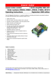
1
maxon motor maxon motor control Operating Instructions 1-Q-EC Amplifier DECS 5/0.05 Order number 274645 November 2006 Edition The DECS (Digital EC Controller Sensorless) is a sensorless 1-quadrant EC amplifier specially designed for use with maxon EC 6 flat motors. Rotor position sensors (Hall sensors) are not required. • • • • • Motor speed is regulated and can be adjusted by the built-in potentiometer or by an external control voltage. Exact adjustment and observance of motor speed can be implemented by monitoring the output "Monitor n" The "Direction" input sets motor rotational direction. The current rotor position is evaluated by using the back-EMF sensing technology Plug and run: The motor connector is suited to the Flex-PCB of the maxon EC 6 flat motor Table of contents 1 2 3 4 5 6 7 8 Safety Instructions............................................................................................................................................2 Performance Data ............................................................................................................................................3 Operating Instructions ......................................................................................................................................4 Functions and Signals ......................................................................................................................................5 Inputs and Output.............................................................................................................................................6 Dimension Drawing ..........................................................................................................................................7 Pin assignment.................................................................................................................................................8 maxon EC 6 flat motor data..............................................................................................................................9 The latest edition of these operating instructions may be found on the internet under http://www.maxonmotor.com category <Service & Downloads>. maxon document number: 567464 - 02 maxon motor 1-Q-EC Amplifier DECS 5/0.05 sensorless Operating Instructions 1 Safety Instructions Skilled Personnel Only experienced, skilled personnel should install and start the equipment. Statutory regulations The user must ensure that the amplifier and the components belonging to it are assembled and connected according to local statutory regulations. Load disconnected For initial operation, the motor should be free running, i.e. with the load disconnected. Additional safety equipment Any electronic apparatus is, in principle, not fail-safe. Machines and apparatus must therefore be fitted with independent monitoring and safety equipment. If the equipment breaks down, if it is operated incorrectly, if the control unit breaks down or if the cables break, etc., it must be ensured that the drive or the complete apparatus is kept in a safe operating mode. Repairs Repairs may only be carried out by authorised personnel or the manufacturer. It is dangerous for the user to carry out any repairs. Danger Ensure that no apparatus is connected to the electrical supply during installation of the DECS 5/0.05. After switching on, do not touch any live parts! Wiring procedure All cable connections should only be connected or disconnected when the power is switched off. Max. supply voltage Make sure that the supply voltage is between 4.5 and 5.5 VDC. Voltages higher than 6 VDC or of wrong polarity will destroy the unit. Start-up procedure Start-up problems may occur in unfavourable applications through the principle of brushless commutation. This is the case with high friction torque, a very high load moment of intertia and in general. Electrostatic sensitive device (ESD) 2 maxon motor control November 2006 Edition / Subject to change maxon motor Operating Instructions 1-Q-EC Amplifier DECS 5/0.05 sensorless 2 Performance Data 2.1 Electrical data Supply voltage Vcc ........................................................................................4.5 – 5.5 VDC Continuous output current Icont ..................................................................................50 mA Max. output current Imax ..........................................................................................100 mA Max. output voltage ....................................................................................................3.5 V Current consumption (no load at rotor shaft) .......................... n= 1 000 min-1: typ. 8 mA 1 ............................................................................................. n= 15 000 min-1: typ. 11 mA 1 Speed range ...................................................................................... 1000 ... 15 000 min-1 2.2 Inputs Direction ................................................................logic signal (5 V) or switch against Gnd 2.3 Outputs Monitor n...................................................................................................logic signal (5 V) 2.4 Motor connections Motor winding 1 Motor winding 2 Motor winding 3 2.5 Ambient temperature / humidity range Operation.......................................................................................................... -0 ... +60°C Storage ........................................................................................................... -40 ... +85°C No condensation................................................................................................ 20 ... 80 % 2.6 Mechanical data Weight .............................................................................................................. approx. 3 g Dimensions (L x W x H) .........................................................................20 x 29.7 x 12 mm Mounting........................................................................ 2 mounting holes, diameter 2 mm Mounting hole distance ...............................................................................15.6 x 16.2 mm 2.7 Terminals Power / Signal Screw terminals J1 ..................................................................................................4 poles Pitch...................................................................................................................... 2.54 mm AWG 26-20 ............................................................................................... 0.14 ... 0.5 mm2 Motor terminal Flex print connector J2 ............................................................................................3 poles Pitch........................................................................................................................ 1.0 mm Suitable for ......................................................................................maxon EC 6 flat motor 1 technical data are only valid for use with maxon EC 6 flat motors, order number #263800 November 2006 Edition / subject to change maxon motor control 3 maxon motor 1-Q-EC Amplifier DECS 5/0.05 sensorless Operating Instructions 3 Operating Instructions 3.1 Step 1 "Pre-adjusting potentiometer P1" By pre-adjusting the set value potentiometer P1 starting conditions are established. Turn set value potentiometer P1 fully right (CW). This adjustment complies with approximately 1'000 rpm motor speed. P1 CW 3.2 Step 2 "Connect maxon EC 6 flat motor" À Pull out the slider of the Flex-to-PCB plug. Á Plug in the Flex-PCB of the maxon EC 6 flat motor carefully. Make sure copper surface is facing up. Â Pull in the slider of the Flex-to-PCB plug again. 3 J2 3.3 1 2 Step 3 "Connect power supply" Any available power supply can be used, as long as it meets the minimum requirements set out below. Power supply requirements Output voltage Ripple Output current Vcc min. 4.5 VDC; Vcc max. 5.5 VDC <5% > 100mA Switch off supply voltage. Connect power supply at: +Vcc Gnd 1 2 J1 +Vcc Gnd Switch on supply voltage. J1 terminal [1] J1 terminal [2] Caution! Voltages higher than 6 VDC or of wrong polarity will destroy the unit. 4 maxon motor control November 2006 Edition / Subject to change maxon motor Operating Instructions 3.4 1-Q-EC Amplifier DECS 5/0.05 sensorless Step 4 "Adjust motor speed" The required motor speed is adjusted through the built-in potentiometer or by an external control voltage (see also chapter 4.3 "Set value selection, Solder bridge JP1" and chapter 5.1.2."Set value") turn to the right (CW) turn to the left (CCW) multi-turn (12) potentiometer motor speed decreases fully right = approx. 1'000 rpm motor speed increases fully left = approx. 15'000 rpm approx. 1'167 rpm / turn 4 Functions and Signals 4.1 Start-up procedure Depending on the rotor start position and size of the coupled load, there is a start-up procedure prior to the motor’s run-up. During the start-up procedure, the motor shaft may temporarily make right-left rotary motions! Note: A reliable start-up can be impossible with very high load inertia. 4.2 Current limitation The power stage is internally current limited to approx. 100 mA. 2 4.3 Set value selection, Solder bridge JP1 Closing the solder bridge JP1 activates the internal set value potentiometer. Solder bridge JP1 Mode speed setting via external voltage open speed setting via internal potentiometer closed JP1 2 Due to the maximum output voltage of 3.5V and the maxon EC 6 flat motor (order number #263800) at a terminal resistance of 68 Ω the phase current is practically limited to approx. 50 mA. November 2006 Edition / subject to change maxon motor control 5 maxon motor 1-Q-EC Amplifier DECS 5/0.05 sensorless Operating Instructions 5 Inputs and Output 5.1 5.1.1 Inputs "Direction" The motor shaft’s direction is set by the "Direction" input at J1 terminal [3]. Input voltage range Input current Continuous over voltage protection Clockwise (CW) Counter-clockwise (CCW) 5.1.2 0 ... +5 V type -250 µA (internal current source to +5 V) -10 V ... +10 V Set input to Gnd or input voltage < 0.8 V Input open or input voltage > 2.4 V "Set value" Use of internal potentiometer P1 (JP1 = closed) Potentiometer – rotation direction left right Potentiometer Function P1 Speed control with internal potentiometer Motor speed higher Motor speed lower Use of external control voltage (JP1=open) The voltage at the "Set value" solder pad sets the speed. The speed changes proportionately to the set value. The adjustable speed range is 1'000 min-1 (0 V) ... 15'000 min-1 (5 V) Input voltage range Input impedance Continuous over voltage protection Set value 6 maxon motor control 0 ... +5 V (reference against Gnd) 100 kΩ -10 V ... +10 V Gnd November 2006 Edition / Subject to change maxon motor Operating Instructions 5.2 5.2.1 1-Q-EC Amplifier DECS 5/0.05 sensorless Output "Monitor n" The motor shaft speed can be monitored at the "Monitor n" output J1 terminal [4]. The actual speed is available as a digital signal (high/low) and corresponds to the electrical rotational speed ( = 4 times the mechanical rotational speed).3 Output voltage range Output resistance Output current 0 ... +5 V 100 Ohm max. 10 mA against Gnd Voltage value 'low' Voltage value 'high' max. 0.3 V (no load) min. 4.5 V (no load) Sought: frequency at the "Monitor n" output f Monitor n = n 15 [ Hz ] n = Speed [rpm] Sought: motor shaft speed nset = f Monitor n ⋅ 15 [rpm] fMonitor n = Frequency at the "Monitor n" output [Hz] 6 Dimension Drawing Dimensions in [mm] 29.7 3 20.0 15.6 16.2 are only valid for use with maxon EC 6 flat motors (8 pole permanent magnet) November 2006 Edition / subject to change maxon motor control 7 maxon motor 1-Q-EC Amplifier DECS 5/0.05 sensorless Operating Instructions 7 Pin assignment 7.1 Pin assignment J1 Power / Signal 1 2 3 4 +Vcc 4.5 - 5.5 VDC Gnd Direction Monitor n 1 2 3 4 J1 Screw terminal Pitch AWG 26-20 7.2 4 poles 2.54 mm 0.14 ... 0.5 mm2 Pin assignment J2 Motor J2 8 maxon motor control 1 2 3 1 2 3 Motor winding 3 Motor winding 2 Motor winding 1 Flex print connector Pitch 3 poles, top contact 1.0 mm Note: Motor terminals suited to maxon EC 6 Flat motor sensorless November 2006 Edition / Subject to change maxon motor Operating Instructions 1-Q-EC Amplifier DECS 5/0.05 sensorless 8 maxon EC 6 flat motor data November 2006 Edition / subject to change maxon motor control 9