1
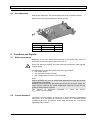
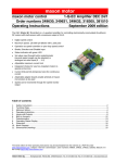
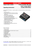
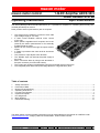
maxon motor
maxon motor control
Operating Instructions
1-Q-EC Amplifier AECS 35/3
Order number 215738
April 2006 Edition
The AECS (Analogue EC Controller Sensorless) is a 1-quadrant EC amplifier for controlling electronically commutated (brushless) DC motors.
Rotor position sensors (Hall sensors) are not required.
•
•
•
•
•
•
•
•
•
•
The electronics are flexible to use due to their wide
input voltage range (8 - 35 VDC).
A fixed current limitation restricts motor current
to 5 A max.
Motor speed is regulated and if required, can be adjusted by the built-in potentiometer or an externally
predetermined set value.
Speed can be monitored through the speed monitor
output.
A “Brake” input allows the motor shaft to slow down
to a halt.
The „Direction” input adjusts motor direction.
The “Disable” input can interrupt the power supply to
the motor.
Motor connection either by using screw terminals or
flex print connector (for maxon flat motors).
The current rotor position is evaluated by using the back-EMF sensing technique.
The integrated power MOS-FET power stage produces a high efficiency level.
Table of contents
1
2
3
4
5
6
7
8
9
Safety Instructions ........................................................................................................................................... 2
Performance Data............................................................................................................................................ 3
Minimum External Wiring................................................................................................................................. 4
Operating Instructions...................................................................................................................................... 6
Functions and Signals ..................................................................................................................................... 7
Inputs and Outputs .......................................................................................................................................... 9
Pin assignment .............................................................................................................................................. 15
Block Diagram ............................................................................................................................................... 17
Dimension Drawing........................................................................................................................................ 17
The latest edition of these operating instructions may be downloaded from the internet as a PDF-file under
www.maxonmotor.com, category «Service & Downloads», Order number 215738.
maxon motor
1-Q-EC Amplifier AECS 35/3 sensorless
Operating Instructions
1 Safety Instructions
Skilled Personnel
Only experienced, skilled personnel should install and start the equipment.
Statutory regulations
The user must ensure that the amplifier and the components belonging to it are
assembled and connected according to local statutory regulations.
Load disconnected
For initial operation, the motor should be free running, i.e. with the load
disconnected.
Additional safety equipment
Any electronic apparatus is, in principle, not fail-safe. Machines and apparatus
must therefore be fitted with independent monitoring and safety equipment. If the
equipment breaks down, if it is operated incorrectly, if the control unit breaks
down or if the cables break, etc., it must be ensured that the drive or the
complete apparatus is kept in a safe operating mode.
Repairs
Repairs may only be carried out by authorised personnel or the manufacturer. It
is dangerous for the user to carry out any repairs.
Danger
Ensure that no apparatus is connected to the electrical supply during installation
of the AECS 35/3. After switching on, do not touch any live parts!
Wiring procedure
All cable connections should only be connected or disconnected when the power
is switched off.
Max. supply voltage
Make sure that the supply voltage is between 8 and 35 VDC. Voltages higher
than 35 VDC or of wrong polarity will destroy the unit.
Start-up procedure
Start-up problems may occur in unfavourable applications through the principle
of sensorless commutation. This is the case with high friction torque, a very high
load moment of intertia and in general, applications of flat motors operated at
high voltages (above motor’s nominal voltage).
Electrostatic sensitive device (ESD)
2 maxon motor control
April 2006 Edition / Subject to change
maxon motor
Operating Instructions
1-Q-EC Amplifier AECS 35/3 sensorless
2 Performance Data
2.1
Electrical data
Supply voltage VCC ....................................................................................................... 8 - 35 VDC
Continuous output current Icont .................................................................................................. 3 A
Max. output current Imax (limited internally) ............................................................................... 5 A
Switching frequency of power stage .............................................................................typ. 40 kHz
Speed range (motor with 1 pole pair)........................................................ typ. 1000 ... 90 000 rpm
2.2
Inputs
Direction ........................................................................... logic signal (5 V) or switch against Gnd
Open or high level = clockwise
at Gnd = counter-clockwise
Brake ................................................................................ logic signal (5 V) or switch against Gnd
Open or high level = motor shaft turns
at Gnd = motor shaft stops
Disable................................................................................................................. logic signal (5 V)
Open or low level = motor shaft turns
High level = motor is separated from supply
Set value...............................................................................................analogue input (0.8 ... 5 V)
2.3
Outputs
Monitor n................................................................... open collector (pull-up 22 kΩ at 5 V, 10 mA)
Speed monitoring NOS............................................ open collector (pull-up 4.7 kΩ at 5 V, 10 mA)
Control voltage OUT ............................................................................. analogue output (0 ... 5 V)
2.4
Motor connections
Motor winding 1
Motor winding 2
Motor winding 3
2.5
Ambient temperature / humidity range
Operation.......................................................................................................................0 ... +40°C
Storage ...................................................................................................................... -40 ... +85°C
No condensation........................................................................................................... 20 ... 80 %
2.6
Mechanical data
Weight ........................................................................................................................approx. 20 g
Dimensions (L x W x H) ....................................................................................... 74 x 51 x 20 mm
Fastening.................................................................4 distance pins hexagonal M3 internal thread
Mounting hole separation ...................................................................................... 63.2 x 40.6 mm
2.7
Terminals
Power / Signal
Screw terminals J1 ............................................................................................................. 9 poles
Pitch .................................................................................................................................2.54 mm
AWG 26-20 .......................................................................................................... 0.14 ... 0.5 mm2
Motor terminal
Screw terminals J2 ............................................................................................................. 3 poles
Pitch .................................................................................................................................2.54 mm
2
AWG 26-20 .......................................................................................................... 0.14 ... 0.5 mm
Flex print connector J3 ....................................................................................................... 4 poles
Pitch ...................................................................................................................................1.0 mm
April 2006 Edition / Subject to change
maxon motor control 3
maxon motor
1-Q-EC Amplifier AECS 35/3 sensorless
Operating Instructions
3 Minimum External Wiring
3.1
Power Supply / Motor
Application with maxon EC motor
Application with maxon EC Flat motor
4 maxon motor control
April 2006 Edition / Subject to change
maxon motor
Operating Instructions
3.2
1-Q-EC Amplifier AECS 35/3 sensorless
Set value input
with internal potentiometer P1
with external potentiometer
with external set value +0.8 … +5 V
April 2006 Edition / Subject to change
maxon motor control 5
maxon motor
1-Q-EC Amplifier AECS 35/3 sensorless
Operating Instructions
4 Operating Instructions
4.1
Power supply layout
Any available power supply can be used, as long as it meets the minimum requirements set out below.
During set up and adjustment phases, we recommend separating the motor
mechanically from the machine to prevent damage from uncontrolled motion.
Power supply requirements
Output voltage
Ripple
Output current
VCC min. 8 VDC; VCC max. 35 VDC
<5%
depending on load,
continuous max. 3 A
acceleration, short-time max. 5 A
The required voltage can be calculated as follows:
Known values:
• Operating torque MB [mNm]
• Operating speed nB [rpm]
• Nominal motor voltage UN [V]
• Motor no-load speed at UN, n0 [rpm]
• Speed/torque gradient of motor ∆n/∆M [rpm/mNm]
Sought values:
• Supply voltage VCC [V]
Solution:
Vcc =
UN
∆n
⋅ ( nB +
⋅ M B ) + 1.5V
n0
∆M
Choose a power supply that can supply this calculated voltage under load.
The formula takes account of a 1.5 max. voltage drop at power stage.
What speed do I reach with my power supply:
⎡
n
n B = ⎢(VCC − 1.5 V ) ⋅ 0
UN
⎣
⎤ ⎡ ∆n
⎤
⋅MB⎥
⎥−⎢
⎦
⎦ ⎣ ∆M
Note:
Please note chapter 6.1.2, „Brake” when using the “Brake” input!
6 maxon motor control
April 2006 Edition / Subject to change
maxon motor
Operating Instructions
4.2
1-Q-EC Amplifier AECS 35/3 sensorless
Pre-adjustment
With the pre-adjustment, the potentiometers are set in a preferred position.
AECS units in the original packing are already pre-set.
P1
JP1
JP2
Pre-adjustment
Speed
Speed range
Speed mode
50%
open
open
5 Functions and Signals
5.1
Start-up procedure
Depending on the rotor start position and size of the coupled load, there is a
short build-up procedure prior to the motor’s run-up.
During the start-up procedure, the motor shaft may temporarily make right-left
rotary motions!
The following points are detrimental to the start-up procedure:
• high friction torque
• very high load moment of intertia
• high voltages (above motor’s nominal voltage)
Note:
Start-up problems may occur in unfavourable applications through the principle
of sensorless commutation.
Multipole motors (maxon EC flat motors) should only be run with a closed JP1
built-in jumper, otherwise the control amplification would be too high and the
speed controller starts to oscillate.
This behavior is particularly noticeable in maxon flat motors.
(VCC > motor nominal voltage)
5.2
Current limitation
The AECS’s current limitation is around 5 A, in which operation is permissible
during max. 20 s. The maximum continuous current is 3 A, otherwise thermal
overload would occur. The AECS’s power stage and motor are not protected
against thermal overload.
April 2006 Edition / Subject to change
maxon motor control 7
maxon motor
1-Q-EC Amplifier AECS 35/3 sensorless
5.3
Operating Instructions
Speed range, Jumper JP1
The maximum speed is limited by the supply voltage and the speed that can be
best adjusted at the set value input.
Jumper JP1 allows two speed ranges:
Motor with
1 pole pair
Maximum speed
Motor with
4 pole pairs
Motor with
8 pole pairs
open
12 000 rpm
3 250 rpm
1 625 rpm
closed
90 000 rpm
22 500 rpm
11 250 rpm
Jumper JP1
Important:
Some motor types allow only one speed range.
See maxon catalogue “Max permissible speed”.
Multipole motors (maxon EC flat motors) should only
be operated with a closed JP1 built-in jumper, otherwise the control amplification would be too high and
the speed controller would start to oscillate.
The motor voltage cannot be reduced to 0 V because
of the commutation process, therefore the motor must
be operated at a minimum speed, depending on operating voltage, load and motor type.
The minimum speed is determined by the speed constants and minimum motor voltage. The AECS’s minimum motor voltage is around 10% of operating voltage.
Example: VCC = 24 V, kn = 195 rpm V-1
=> Motor voltage UM = 2.4 V, nmin = approx. 500 rpm
5.4
Speed mode, Jumper JP2
Speed control is deactivated by closing jumper JP2. The motor turns with the
maximum speed.
8 maxon motor control
Jumper JP2
Speed mode
open
Speed control (closed loop)
closed
True commutation
April 2006 Edition / Subject to change
maxon motor
Operating Instructions
1-Q-EC Amplifier AECS 35/3 sensorless
6 Inputs and Outputs
6.1
6.1.1
Inputs
„Direction“
The motor shaft’s direction is predetermined through the „Direction” input.
Input voltage range
Input current
Overvoltage protection
0 ... +5 V
max. -200 µA
(internal current source at +5 V)
not protected
Clockwise (CW)
Counter-clockwise (CCW)
Input open or input voltage > 4.0 V
Set input to Gnd or input voltage < 1.0 V
Wiring examples:
Switch
Relay contact NPN transistor Optocoupler
Clockwise (CW) Switch
open
Contact
open
Counter-clockwise (CCW) Switch
closed
Contact
closed
April 2006 Edition / Subject to change
Transistor
blocked
IC = 0
Transistor
conductive
IC = 200 µA
Transistor
blocked
IC = 0
Transistor
conductive
IC = 200 µA
Logic
component
HIGH Level
> 4.0 V
LOW Level
< 1.0 V
maxon motor control 9
maxon motor
1-Q-EC Amplifier AECS 35/3 sensorless
6.1.2
Operating Instructions
„Brake“
If the input is not wired or the applied voltage is greater than 4.0 V, the brake
function is deactivated.
If the input is placed at Gnd-potential or the applied voltage is lower than 1.0 V,
the brake function is activated and the motor shaft slows down to a halt, shortcircuiting the motor windings. The motor windings remain short-circuited until
the brake function is deactivated.
Input voltage range
Input current
Overvoltage protection
0 ... +5 V
max. -200 µA
(internal current source at +5 V)
Not protected
Brake function not active
Brake function aktive
Input open or input voltage > 4.0 V
Set input to Gnd or input voltage < 1.0 V
Wiring examples:
Switch
Relay contact
Brake function not active Switch
open
Contact
open
Brake function active Switch
closed
Contact
closed
NPN transistor Optocoupler
Logic
component
Transistor
blocked
IC = 0
Transistor
conductive
IC = 200 µA
HIGH Level
> 4.0 V
Transistor
blocked
IC = 0
Transistor
conductive
IC = 200 µA
LOW Level
< 1.0 V
The maximum permitted brake speed is limited by the maximum permitted
short-circuit current and maximum kinetic energy:
• I <= 10 A
• Wk <= 20 Ws
The values can be calculated as follows:
The maximum permitted brake speed can be calculated from the motor data:
nmax = 10 A ⋅ k n ⋅ (RPh− Ph + 0.13Ω)
[rpm]
max. permitted brake speed
-1
limited by brake kn = Speed constant [rpm V ]
current (I = 10 A) RPh-Ph = Terminal resistance phase-phase [Ω]
•
With the given moment of inertia, the maximum speed can be determined
using the following formula:
max. permitted brake speed
limited by kinetic energy nmax =
(Wk = 20 Ws)
365
⋅ 10 000
JR + JL
[rpm]
JR = Rotor inertia [g cm2]
JL = Load inertia [g cm2]
•
•
10 maxon motor control
April 2006 Edition / Subject to change
maxon motor
Operating Instructions
6.1.3
1-Q-EC Amplifier AECS 35/3 sensorless
„Disable“
Enable or disable the power stage. If the input "Disable" is not wired or placed
at Gnd-potential or the applied voltage is lower than 0.4 V, the amplifier is activated. If the applied voltage is greater than 2.4 V, the power stage is blocked
and the motor shaft freewheels and slows down.
The “Disable” input is protected against overvoltage.
Input voltage range
Input impedance
Max. input voltage
Power stage active
Power stage inactive
0 ... +24 VDC
approx. 6 kΩ resistance against Gnd
0 ... +25 VDC
Input open or set to Gnd or input voltage < 0.4
V
Input voltage > 2.4 V
Wiring examples:
a) switch open = „Enable“; switch closed = „Disable“
Switch
Relay contact NPN transistor Optocoupler
Power stage active
Motor winding fed with current
Power stage inactive
Motor shaft freewheels and
slows down
Switch
open
Switch
closed
Contact
open
Contact
closed
Transistor
blocked IE = 0
Transistor conductive IE > 0
Logic
component
Transistor
LOW Level
blocked IE = 0
Transistor con- HIGH Level
ductive IE > 0
b) switch open = „Disable“; switch closed = „Enable“
Switch
Relay contact NPN transistor Optocoupler
Power stage active
Motor winding fed with current
Power stage inactive
Motor shaft freewheels and
slows down
Calculation help
Switch
closed
Switch
open
Contact
closed
Contact
open
Known value: +Vext = +3.3 … +24 VDC
Sought value:
⎞
⎛ V
Transistor conductive IC > 0
Transistor
blocked IC = 0
Rext ≤ ⎜⎜ ext ⋅ 6000 Ω ⎟⎟ − 6000 Ω
⎠
⎝ 2.4 V
April 2006 Edition / Subject to change
Transistor conductive IC > 0
Transistor
blocked IC = 0
[Ω]
maxon motor control 11
maxon motor
1-Q-EC Amplifier AECS 35/3 sensorless
6.1.4
Operating Instructions
“Set value”
Set value input via external power supply
The voltage at the “Set value” input predetermines the speed set value.
The speed changes proportionately to the set value.
Input voltage range
Input impedance
Overvoltage protection
0.8 ... +5 V (reference against Gnd)
> 1M Ω
not protected
Set value input via internal potentiometer P1
The “Set value” input (J1, clamp 6) must be connected to the „Control voltage
OUT” output (J1, clamp 7).
Note:
The lower and upper limitation of speed adjustment must be observed (see
chapter 5.3, “Speed range, Jumper JP1”).
Set value input via external potentiometer
Internal potentiometer P1 at right end stop
Value of external potentiometer
100 kΩ
12 maxon motor control
April 2006 Edition / Subject to change
maxon motor
Operating Instructions
6.2
6.2.1
1-Q-EC Amplifier AECS 35/3 sensorless
Outputs
„Control voltage OUT“
If the internal potentiometer P1 is used for speed adjustment, the “Control voltage OUT” output (clamp 7) must be electrically connected to the „Set value” input (clamp 6).
6.2.2
Output voltage range
Output impedance
0 ... +5 V
approx. 10 kΩ
Potentiometer P1 right end stop
Potentiometer P1 left end stop
+5 VDC
0V
Speed monitor „NOS“
The NOS output (Non Operating Signal) can be used for status monitoring.
Output voltage range
Output current
0 ... +5 V
max. 10 mA against Gnd
Voltage value 'low'
Motor shaft turns
max. 0.3 V
Motor shaft stops
+5 V
(4.7 kΩ internal pull-up resistor at +5 V)
Voltage value 'high'
Note:
Cable failure or lack of supply voltage cannot be monitored!
'High' level is displayed during the motor’s start-up cycle.
April 2006 Edition / Subject to change
maxon motor control 13
maxon motor
1-Q-EC Amplifier AECS 35/3 sensorless
6.2.3
Operating Instructions
„Monitor n“
The motor shaft’s set speed can be monitored at the electronics „Monitor n” output. The set speed is available as a digital signal (high/low) and corresponds to
half the commutation frequency.
Output voltage range
Output current
0 ... +5 V
max. 10 mA against Gnd
Voltage value 'low'
Voltage value 'high'
max. 0.3 V
+5 V
(22 kΩ internal pull-up resistor at +5 V)
Sought: frequency at the „Monitor n” output
f Monitor n =
n set ⋅ z Pol
20
[ Hz ]
nset = Speed [rpm]
zPol = Number of the motor’s pole pairs
Sought: motor shaft speed
n set =
f Monitor n ⋅ 20
z Pol
[rpm]
fMonitor n = Frequency at the „Monitor n” output [Hz]
zPol = Number of the motor’s pole pairs
14 maxon motor control
April 2006 Edition / Subject to change
maxon motor
Operating Instructions
1-Q-EC Amplifier AECS 35/3 sensorless
7 Pin assignment
7.1
Pin assignment J1 Power / Signal
9
8
7
6
5
4
3
2
1
Screw terminal
Pitch
AWG 26-20
7.2
Monitor n
Speed monitoring NOS
Control voltage OUT
Set value
Disable
Brake
Direction
Gnd
+VCC 8 … 35VDC
9 poles
2.54 mm
0.14 ... 0.5 mm2
Pin assignment J2 motor connection
1
2
3
Screw terminal
Pitch
AWG 26-20
Note:
Motor terminals matching, e.g:
April 2006 Edition / Subject to change
Motor winding 1
Motor winding 2
Motor winding 3
3 poles
2.54 mm
0.14 ... 0.5 mm2
maxon EC motor
maxon EC motor
maxon EC motor
maxon EC motor
EC∅16 sensorless
EC∅22 sensorless
EC∅32
EC∅40
maxon motor control 15
maxon motor
1-Q-EC Amplifier AECS 35/3 sensorless
7.3
Operating Instructions
Pin assignment J3 (4 poles flex print connector)
1
2
3
4
Flex print connector
Pitch
Note:
Motor terminals matching, e.g:
16 maxon motor control
Motor winding 1
Motor winding 2
Motor winding 3
Neutral point Y (not used)
4 poles, top contact style
1.0 mm
maxon EC∅14 Flat motor sensorless
maxon EC∅20 Flat motor sensorless
maxon EC∅32 Flat motor sensorless
maxon EC∅45 Flat motor sensorless
April 2006 Edition / Subject to change
maxon motor
Operating Instructions
1-Q-EC Amplifier AECS 35/3 sensorless
8 Block Diagram
9 Dimension Drawing
Dimensions in [mm]
April 2006 Edition / Subject to change
maxon motor control 17