1
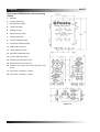
®
Installation Manual
M300C ! M250C ! M216C ! M190C
GB
Marine Power
Part No N40475
N40475
Title
Perkins M300C, M250C,
M216C & M190C
Installation Manual
6 cylinder, turbocharged, intercooled, diesel engine for
marine propulsion applications
Publication N40475, Issue 2
© Proprietary information of Wimborne Marine Power Centre, all rights reserved.
The information is correct at the time of print.
Published in February 2011 by Wimborne Marine Power Centre,
Wimborne Marine Power Centre, Wimborne, Dorset, England BH21 7PW
Tel:+44(0)1202 893720 Fax: +44(0)1202 851700 E-mail: [email protected]
www.perkins-sabre.com
Title
N40475
Foreword
Thank you purchasing the Perkins M300C, M250C, M216C & M190C marine diesel engine. This manual
contains information for the correct installation of your Perkins engine.
Information contained in this manual is correct at the time of printing. Wimborne Marine Power Centre
reserves the right to make changes at any time. If there are any differences between this manual and your
engine, please contact the Wimborne Marine Power Centre.
General safety precautions
•
If your skin comes into contact with high-pressure
fuel, obtain medical assistance immediately.
These safety precautions are important. You must refer
also to the local regulations in the country of use. Some
items only refer to specific applications.
•
Diesel fuel and lubricating oil (especially used
lubricating oil) can damage the skin of certain
persons. Protect your hands with gloves or a special
solution to protect the skin.
•
Do not wear clothing which is contaminated
by lubricating oil. Do not put material which is
contaminated with oil into the pockets of clothing.
•
Discard used lubricating oil in accordance with local
regulations to prevent contamination.
•
Use extreme care if emergency repairs must be
made at sea or in adverse conditions.
•
The combustible material of some components of
the engine (for example certain seals) can become
extremely dangerous if it is burned. Never allow this
burnt material to come into contact with the skin or
with the eyes.
•
Always close the seacock before the removal of any
component of the auxiliary water circuit.
•
Wear a face mask if the glass fibre cover of the
turbocharger is to be removed or fitted.
•
Always use a safety cage to protect the operator
when a component is to be pressure tested in
a container of water. Fit safety wires to secure
the plugs which seal the hose connections of a
component which is to be pressure tested.
•
Do not allow compressed air to contact your skin. If
compressed air enters your skin, obtain medical help
immediately.
•
Only use these engines in the type of application for
which they have been designed.
•
Do not change the specification of the engine.
•
Do not smoke when you put fuel in the tank.
•
Clean away fuel which has been spilt. Material which
has been contaminated by fuel must be moved to a
safe place.
•
Do not put fuel in the tank while the engine runs
(unless it is absolutely necessary).
•
Do not clean, add lubricating oil, or adjust the engine
while it runs (unless you have had the correct
training; even then extreme care must be used to
prevent injury).
•
Do not make adjustments that you do not understand.
•
Ensure that the engine does not run in a location
where it can cause a concentration of toxic
emissions.
•
Other persons must be kept at a safe distance
while the engine, auxiliary equipment or boat is in
operation.
•
Do not permit loose clothing or long hair near moving
parts.
•
Keep away from moving parts during engine
operation.
Warning! Some moving parts cannot be seen clearly
while the engine runs.
•
Do not operate the engine if a safety guard has been
removed.
•
Do not remove the filler cap or any component of the
cooling system while the engine is hot and while the
coolant is under pressure, because dangerous hot
coolant can be discharged.
•
Do not use salt water or any other coolant which can
cause corrosion in the closed circuit of the cooling
system.
•
Do not allow sparks or fire near the batteries
(especially when the batteries are on charge)
because the gases from the electrolyte are highly
flammable. The battery fluid is dangerous to the skin
and especially to the eyes.
•
Disconnect the battery terminals before a repair is
made to the electrical system.
•
Only one person must control the engine.
•
Ensure that the engine is operated only from the
control panel or from the operators position.
N40475
Contents
Chapter ....................................................................................................................................... Page
1 Location of engine installation points .........................................1
2 Engine mounting ...........................................................................3
Installation angles ........................................................................................... 3
Nose down capability........................................................................... 3
Engine mounting brackets ............................................................................. 4
Flexible engine mounts................................................................................... 5
Engine bearers................................................................................................. 6
3 Propeller shafts and couplings ....................................................7
Propeller shafts ............................................................................................... 7
4 Exhaust systems ...........................................................................9
Wet systems..................................................................................................... 9
Dry systems .................................................................................................... 11
Part dry, part wet systems ............................................................................. 12
Water lift systems ........................................................................................... 12
Silencers.......................................................................................................... 13
5 Engine room ventilation...............................................................15
6 Engine cooling systems ..............................................................17
Auxiliary water systems................................................................................. 17
Keel cooling system ....................................................................................... 18
7 Fuel systems .................................................................................19
Cleanliness of fuel system components ...................................................... 19
Cleanliness of the engine ................................................................... 19
Environment ........................................................................................ 19
New components................................................................................. 19
Refuelling ............................................................................................. 19
Fuel connections ................................................................................. 19
Thread details of the connections on the engines for fuel pipes ... 20
Typical fuel systems ........................................................................... 21
8 Engine electrical systems............................................................23
Engine wiring looms ...................................................................................... 23
Breakers .......................................................................................................... 24
Interconnecting cables .................................................................................. 25
Contents
Instrument panels........................................................................................... 26
Main panel ............................................................................................ 26
Auxiliary panel ..................................................................................... 27
Mini Marine Power Display (MMPD) digital panel............................. 28
Keyswitch panel .................................................................................. 29
Possible panel configurations. .......................................................... 30
Mini Marine Power Dispaly (MMPD) instructions ............................. 31
CAN Data Link ..................................................................................... 35
Marine Junction Box (MJB) ........................................................................... 36
Single engine MJB features and mounting details .......................... 37
Twin engine MJB features and mounting details ............................. 38
Power connections ............................................................................. 39
Current requirements 12 or 24 vdc system ...................................... 39
ECM port or starboard interface connectors .................................... 39
Grounding the battery negative ......................................................... 39
Port or starboard expansion connectors .......................................... 40
Diagnostic lamp (Pin 2)....................................................................... 41
Warning lamp (Pin 1) ........................................................................... 41
- Battery (Pin 11) .................................................................................. 41
Keyswitch (Pin 12)............................................................................... 41
Maintenance Clear switch (Pin 16) .................................................... 41
Cold start system .......................................................................................... 42
Cold start data 12V and 24V .............................................................. 42
Battery performance .......................................................................... 42
Battery to starter lead resistance ..................................................... 42
Battery isolator switches .................................................................... 43
Zinc Anode bonding system ......................................................................... 43
Typical system in common use ......................................................... 44
Optional sensors ............................................................................................ 44
Engine wiring harness overview........................................................ 45
Panel harness overview...................................................................... 46
Wiring diagrams ............................................................................................. 47
Engine wiring harness 1 ..................................................................... 47
Engine wiring harness 2 ..................................................................... 48
Engine panels 1 ................................................................................... 49
Interconnecting leads 1 ...................................................................... 50
Master/slave option, port .................................................................... 51
Marine junction box ............................................................................ 52
Master/slave option, starboard .......................................................... 53
Interconnecting leads 2 ...................................................................... 54
Engine panels 2 ................................................................................... 55
9 Engine controls ............................................................................57
N40475
N40475
Contents
10 Provision for power take-off ......................................................59
For axial drives ............................................................................................... 59
For belt drives ................................................................................................. 59
Polar diagram.................................................................................................. 60
11 Calorifier and block heater connections ..................................61
Calorifier .......................................................................................................... 61
Block heater connection points .................................................................... 61
12 Reference data ............................................................................63
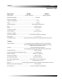
Basic data M300C/M250C .............................................................................. 63
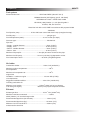
Cooling ............................................................................................................ 63
Fuel system ..................................................................................................... 64
Air intake ......................................................................................................... 64
Lubricating system......................................................................................... 65
Electrical system ............................................................................................ 65
Cold start limits .............................................................................................. 65
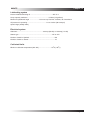
Basic data M216C/M190C .............................................................................. 67
Cooling ............................................................................................................ 67
Fuel system ..................................................................................................... 68
Air intake ......................................................................................................... 68
Lubricating system......................................................................................... 69
Electrical system ............................................................................................ 69
Cold start limits .............................................................................................. 69
Contents
N40475
N40475
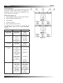
Chapter 1
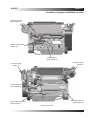
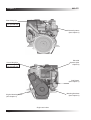
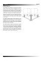
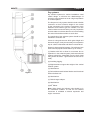
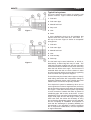
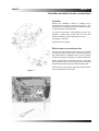
Location of engine installation points
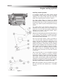
Exhaust Systems
(See chapter 4)
Starter Cables (See
chapter 8)
Bonding Stud
(See chapter 8)
Ventilation (See
chapter 5)
Fuel Feed (See
chapter 7)
Cooling Systems
(See chapter 6)
Mounting Brackets
(See chapter 2)
Engine Mounting Point
(See chapter 2)
Engine side views
Page 1
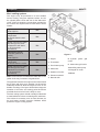
Chapter 1
N40475
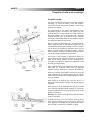
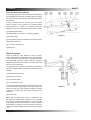
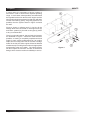
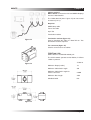
Rear Lifting Eye
Warning!
Use spreader bar.
Exhaust Systems
(See chapter 4)
Electrical
Systems (See
chapter 8)
Front Lifting Eye
Warning!
Use spreader bar.
Fuel Return
(See chapter 7)
Mounting Brackets
(See chapter 2)
Engine Mounting Points
(See chapter 2)
Engine end views
Page 2
N40475
Chapter 2
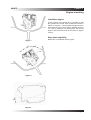
Engine mounting
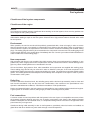
Installation angles
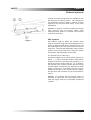
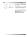
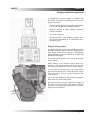
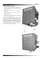
These engines are intended to be mounted so that
the cylinders are vertical, when viewed from ahead or
astern as in figure 1. The operational angles that are
permissible in service are a static installation angle of
17O nose up, adding 3O for planing craft, with a heel
angle of 25O continuous and 35O as shown in figures
2 and 3.
Nose down capability
Details are not available at time of print.
Figure 1
25O
35O
25O
35O
Figure 2
20O
Figure 3.
Page 3
Chapter 2
N40475
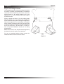
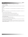
Engine mounting brackets
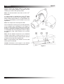
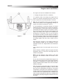
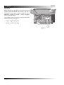
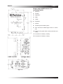
The standard brackets, provide mounting points which
are 76mm (3”) below, and parallel with, the crankshaft
centre line. The brackets may be used to mount the
engine directly on the engine bearers, but for all
applications it is recommended that flexible engine
mounts are used.
Figure 4 shows the holes (1) for the holding down
bolts are slotted, 36 x 17 (1.7/16 x 21/32”) to allow for
some movement during the final stages of alignment.
Where fine alignment is not necessary, for example
when a flexibly jointed drive shaft is used, the bolts
on all four corners of the engine should be positioned
at the end of the slot - all either fully in or fully out.
This will provide additional security in the fixing
arrangements.
Note: Please refer to the GA (General Arrangement)
drawings for specific engine mount positions.
For any non standard options, please contact the
Wimborne Marine Power Centre for advice.
Figure 4
Page 4
N40475
Chapter 2
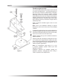
Flexible engine mounts
It is recommended that flexible engine mounts should
be used for all applications. The principal purpose of
the mounts is to reduce the transmission of vibration
from the engine to the hull, but another valuable
advantage is that the mountings reduce the shock
transmitted from the hull to the engine under adverse
weather conditions and also prevent the engine being
inadvertently used as a structural part of the boat,
due to flexing in the hull, a function the engine will not
satisfactorily fulfil.
Figure 5 shows the flexible engine mount for most
applications.
Note: refer to the installation drawing for specific
dimensions, which are for the mount in the unloaded
condition.
To adjust the height of the mount, use the adjuster nut
and bolt (2) against the pad (3) to introduce shims (4).
A maximum of thirteen shims per mount can be used,
eleven at 1mm thick and 2 at 0.5mm thick.
Radially slotted holes (5) can be utilised to obtain the
optimum position.
Engines used with unusual drive arrangements, such
as ‘V’ drives when integral with the engine unit, pose
special mounting problems and recommendations as
to the most suitable mounting arrangement can be
made for specific applications.
Note: For transmission ratios above 2:1 or use
in extreme conditions, please contact your local
distributor for advice.
Figure 5
Installation drawings are available showing the
preferred mounting arrangements when using a
variety of gearboxes and applications.
Page 5
Chapter 2
N40475
Engine bearers
The materials and methods of construction of engine
bearers which have proved to be satisfactory in service
vary to such an extent that it is difficult to lay down
universal guide lines. However, as a rough guide it
can be said the engine bearers should be capable of
supporting a static load of about eight times the weight
of the engine, to cater for the effects of rough seas.
The bearers should be cross connected to give lateral
rigidity, in order to maintain the shaft alignment and
to prevent twisting and racking forces being applied
to the engine.
To enable minimum shaft centre distances to be
achieved in a twin installation, a common centre bearer
supporting the inner mountings of both engines is
sometimes used as shown in figure 6. By this method
shaft centres down to 783mm (31”) may be adopted,
but wider spacing is desirable.
The shaft centres could be theoretically reduced
further, but this would result in the engine accessibility
becoming very restricted, and it would be impossible
to carry out service operations. It should be noted that
if minimum shaft centres are to be adopted, space
must be left in front of and behind the engine to
provide access. A minimum clearance on all sides will
mean that the engine cannot be serviced!
Page 6
Figure 6
N40475
Chapter 3
Propeller shafts and couplings
Propeller shafts
It is recommended that all engines are mounted on flexible
mountings (1), which will reduce noise and vibration,
and will prevent hull movements resulting in forces being
applied to the engine.
The responsibility for the design and installation of the
transmission system connected to the gearbox lies with
the boat designer, the boat builder, the naval architect or
the engine installer. It is recommended that a Torsional
Vibration Analysis (TVA) is carried out on the complete
drive system. Mass Elastic Data can be provided on request
from Wimborne Marine Power Centre.
Figure 1 shows a simple arrangement, where the propeller
shaft is supported only by the gearbox coupling and an
outboard rubber bearing at the propeller end. Entry of water
into the boat is prevented by a shaft seal, which must be
flexibly mounted to allow for engine movement. A flexible
shaft coupling (2) is fitted to the gearbox coupling, to allow
momentary angular misalignment in operation.
This system is only suitable for applications where the
speed, diameter, and unsupported length of the propeller
shaft will not induce ‘whirling’ (i.e. the centrifugal force
generated by the speed of rotation is not sufficient to bend
the shaft into a bow shape).
Figure 1
Figure 1 also shows a cutless bearing (3), flexibly mounted
shaft seals (4), reinforced rubber hose (5), graphited
asbestos string (6), stuffing box (7) and the drive shaft (8).
Where the propeller shaft length is such that it cannot be
simply supported by the gearbox coupling and ‘P’ bracket,
without the risk of whirling, the arrangement shown in figure
2 may be adopted.
Water supply (4) for bearings (use hose from M14 x 1.5
tapping on heat exchanger end cap). End cap with tapping
is optional.
In this case one or more additional bearings (3) are included
in the shaft log, and flexible shaft couplings (2) (which will
accept thrust) are used to permit the engine to move on the
flexible mountings (1) .
Warning! Use a syphon break (5) where a water lift exhaust
system is specified.
A variation of this is to use a thrust block (bearing) at the
point where the shaft emerges from the log into the engine
room, together with constant velocity joints at each end of
the short shaft connected to the gearbox coupling.
Figure 2
Page 7
Chapter 3
Page 8
N40475
N40475
Chapter 4
Exhaust systems
A range of exhaust components are available for use
with all types of exhaust system. The components
are designed to connect together, allowing complex
systems to be built from stock items, to suit most
installations.
Caution: In all types of exhaust system the exhaust
back pressure must not exceed 15kPa, when
measured within 305mm (12 inches) of the exhaust
outlet from the engine.
Figure 1
Wet systems
Wet exhaust systems, where the auxiliary water
used to circulate through the heat exchangers on the
engine is finally dumped into the exhaust pipe to cool
the exhaust gases, are the most common choice for
small craft. Their principal advantage is that a rubber
exhaust hose may be used, with a fairly low surface
temperature, which presents no risk of fire.
The exhaust bore is 125mm (5”).
A general arrangement for such a system is shown on
Figure 1. In many cases the exhaust outlet passes
through the transom, just above the waterline (1). It
will be seen that a minimum fall of 5O (2) is required,
and that the point of water injection must be at least
8 inches above the waterline (3), although the actual
height necessary for a particular boat can only be
decided in the light of the exhaust system design,
and the pitch and roll which may be encountered in
service.
Caution: It is essential that the exhaust system is
designed so that water from the exhaust does not
enter the engine under any conceivable operational
condition.
Page 9
Chapter 4
N40475
Figure 2 shows the exhaust elbow (1) with water
injection and insulating blanket. The elbow can be
rotated (3) to achieve the optimal position.
Note: The exhaust elbow must have a fall of 10O
downwards.
If a taller system is required then a dry 90O elbow
(not shown) can be used on the turbocharger outlet
with the water injected elbow (1). As both elbows use
a clamp, full articulation can be utilised to suit most
applications
Note: The clamps are to be torqued to 9Nm.
Due consideration must be given to providing flexibility
in the exhaust hose, particularly if the engine is
flexibly mounted. Where the exhaust hose must pass
through a bulkhead immediately behind the engine
it is preferable that the arrangement shown in figure
3 is adopted, using rubber bellows (1) to provide
flexibility.
Figure 2
Note: that the bellows should be in an unstrained
condition when fitted, a minimum fall of 5o (3) is
required, and that the point of water injection must be
at least 8 inches above the waterline (2).
Note: A single double hump bellows can be used
where space is restricted.
Caution: Movement of the engine on the flexible
mounts must not be restricted by the exhaust hose.
Figure 3
Page 10
N40475
Chapter 4
Dry systems
Dry exhaust systems for marine installations need
careful design to minimize the disadvantages of
enclosing components that are at a high temperature
in confined spaces.
The first part of a dry system should include a flexible
connection so that excessive weight is not carried
by the connection to the engine. Connections of the
stainless steel bellows type are suitable, but care
must be taken to ensure that they are only required to
accommodate movements that do not involve twisting
the ends of the bellows relative to each other.
The remainder of the exhaust system should be well
insulated to avoid fire risk.
If there is a long exhaust run which gains height as it
leaves the engine, it may be necessary to incorporate a
trap to collect condensate and allow it to be drained.
Figures 4 shows a typical systems. The minimum bore
of the exhaust pipe should be 85mm (3.34 inches).
(1) Bracket with link to allow for movement due to
expansion in the exhaust system (horizontal exhaust
systems should be suspended from the deck head
using similar brackets - rigid brackets should not be
used).
(2) Insulating lagging.
(3) Rigid bracket to support the weight of the vertical
exhaust system.
(4) Heat blanket.
Figure 4
(5) Twin stainless steel belows fitted to avoid torsional
load on bellows unit.
(6) Heat blanket.
(7) Turbocharger adaptor.
(8) Heat blanket.
(9) 90O Elbow.
Note: When fitted, the bellows units should be in
an unstrained condition so that the full bellows
movement is available to absorb expansion and
engine movement.
Page 11
Chapter 4
N40475
Part dry, part wet systems
Even where the engine is mounted well below the waterline
the advantages of a wet system can still be gained, providing
that water injection takes place at a point sufficiently above
the waterline.
In these circumstances the part dry, part wet system
shown in Figure 5 can be utilised. The modular exhaust
components allow a system to be readily constructed,
utilising a tall dry riser, followed by a water injection elbow.
(1) Stainless steel bellows.
(2) Optional high rise extension - not factory supplied.
(3) Flexible hanger.
Figure 5
(4) Point of water injection to be 200mm (8 inches) minimum
height above water line.
(5) 5O minimum average fall.
(6) Water line.
Water lift systems
Figure 6 shows the main features of such a system,
which utilises pressure developed by the exhaust gases
to force a mixture of gas and water to a height which may
be considerably above the engine. When the engine is
stopped the exhaust tank contains the water which falls
back from the exhaust riser.
If a proprietary unit is used the manufacturers instructions
should be carefully followed, but figure 5 identifies the key
features.
(1) Exhaust tank (water lock).
(2) Water injection elbow.
(3) To overboard outlet.
(4) 1/2” bore siphon break.
(5) Top of exhaust riser and point at which the siphon break
is connected to the engine pipe work must be above the
water line under the worst possible conditions (normally
a distance of 450mm (18”) under static conditions will be
sufficient)
(6) Exhaust riser.
Note: that the system must meet the requirement for
the maximum exhaust back pressure to be not greater
than 15kPa, measured within 305mm (12 inches) of the
turbocharger/ exhaust outlet. Minimum volume of exhaust
tank should be 3 times the volume of the water in the riser.
The tank should be installed near the centre-line of sailing
craft.
Page 12
Figure 6
N40475
Chapter 4
Silencers
In some applications a reduction in noise levels from
the exhaust would be desirable and to that extent, a
silencer can be fitted.
The exhaust system ejects the cooling water as
well as silencing the engine’s combustion noise and
removing the exhaust gases. The system must create
minimal restriction to the flow of exhaust gases, known
as back pressure, or the engine may be damaged.
Figure 7
Figure 7 shows an engine sited well above the
waterline (1), with a gradient steeper than 5O to the
back of the boat. The water will run naturally down the
exhaust to the stern. To reduce noise a straightforward
in-line silencer (2) should be used.
Note: The above is used in relation to 15kPa.
Page 13
Chapter 4
Page 14
N40475
N40475
Chapter 5
Engine room ventilation
The engine room must be ventilated for two reasons:
1. To supply the engine with air for combustion.
2. To provide a flow of air through the engine room to
prevent an excessive temperature build up, which may
cause components such as the alternator to overheat.
Note: The air temperature entering the engine should not
exceed 52OC (126OF). The air temperature entering the
engine room should not exceed 60OC (140OF).
Figure 1
In most applications in temperate climates, the engine
will draw air from the engine room. If this is the case then,
as a rough guide, it can be taken that every horsepower
produced by the engines requires, as a minimum, 6.35 sq.
mm, (0.25 sq.ins.) of vent area. If the boat is likely to be
used in hot climates, and if engine room ventilation fans
are fitted, then a vent area of 12.7 sq. mm (0.5 sq.ins.)
per horsepower should be provided. Wherever possible a
flow of air through the engine room should be encouraged
by using forward facing intake vents to take advantage of
ram airflow, together with other vents to allow hot air to
escape.
Noise absorbing chambers (1) with deflector baffles and
noise absorbent material (2) are positioned to direct
ventilation air flow over a large surface area of absorbent
material.
Cross sectional area of air flow path must not be too
small.
With an effective ventilation system the engine air intake
temperature will be no more than 10OC higher than the
outside air temperature.
Note: For the minimum cross section of air duct
per engine see ‘Reference data’ at the back of this
manual.
The air entry vents should be situated where spray is not
likely to enter them and some form of water trap is desirable
(see figure 1). Preferably the air ducts should reach the
engine compartment at the sides of the hull so that water
will fall into the bilge.
When the engines are shut down after a run at high output
in high ambient temperature conditions, it will be found
that very high air temperatures will build up in the engine
compartment. In boats with open cockpits this is usually of
no real consequence but if the engines are mounted below
a wheel house, then unpleasantly warm conditions may
result. In these circumstances engine room ventilation fans
are beneficial, preferably arranged to exhaust air from over
the engine.
Page 15
Chapter 5
Page 16
N40475
N40475
Chapter 6
Engine cooling systems
Auxiliary water systems
A completely separate sea water system should
be provided for each engine to prevent a blockage
resulting in the need to shut down more than one
engine and a typical system is shown in figure 1.
The water intake fitting (4) should not project
appreciably below the bottom of the hull and it should
be situated well clear of other components such as
shafts, logs, rudders to prevent flow problems at high
speeds.
The intake fittings and pipework should have a
minimum bore of 32mm (1.25”) be provided. This
should be of the full flow type giving unobstructed
passage to the water in the open position, with a
minimum bore of 32mm (1.25”).
Between the intake fitting and the sea water pump (1)
on the engine, there should be a strainer (5) which
should be easily accessible for routine examination,
and should be easily removable.
From the sea water strainer a pipe (2) should be
run to the sea water pump inlet connection on the
engine. The pipe may either be mainly rigid, of for
example copper or cupro-nickel, or flexible, but only
flexible hose which is reinforced to prevent collapse
should be used. Rubber hose connections in the sea
water system should be kept as short as possible.
The system must be sufficiently flexible to permit
the engine to move on its flexible mountings. The
sea water pump connection is for hose with a 32mm
(1.25”) bore.
Care should be taken to use compatible materials
in the sea water systems, to prevent excessive
electrolytic corrosion. Systems incorporating copper,
cupro-nickel, stainless steel Type 316, gun-metal,
silver solder, and aluminium brass will generally be
satisfactory. Components made from lead, iron, steel,
aluminium or its alloys, zinc or magnesium, should be
generally avoided. Refer to section 8 on anodes.
Note: Where possible mount the strainer (5) so that
the top is just above the waterline (6) - to facilitate
cleaning.
Figure 1
Page 17
Chapter 6
N40475
Keel cooling system
This engine may be purchased in a form suitable
for keel cooling, using two separate coolers, one for
the cylinder jacket circuit and one for the aftercooler
circuit. Figure 2 shows the connections provided for
the coolers. The requirements for each section are as
follows:
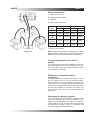
Cylinder Jacket Circuit
Heat rejection.
TBA
Design value for the water
temperature
at the exit from the keel
cooler.
TBA
Design value for the water
flow through the cooler.
*Pipework to suit 45mm
(1.75”) bore hose
connections.
TBA
Aftercooler Circuit
(Includes gearbox oil
cooler)
Heat rejection
TBA
Design value for the water
temperature
at the exit from the cooler.
TBA
Design value for the water
flow through the cooler.
Pipework to suit 45mm
(1.75”) bore hose
connections.
1. Engine
2. Thermostat
3. Fresh water pump
TBA
Note: Under extreme conditions the water flow in the
jacket circuit may increase to 40 gallons/min.
The pipework between the engine and coolers should
be as short and direct as is possible, but should be
sufficiently flexible to allow the engine to move on it’s
flexible mountings. The layout should discourage the
formation of air locks, and venting points should be
provided wherever an air lock is likely to occur.
The keel cooling system should normally be filled with
a water/antifreeze mixture containing 50% antifreeze.
This mixture is necessary even in warm climates, as
the anti freeze contains corrosion inhibitors which
protect the engine cooling system.
Page 18
Figure 2
4. Aftercooler
5. Gearbox oil cooler
6. Exhaust manifold
7. Remote tank
8. Cylinder
cooler
jacket
grid
9. Aftercooler grid cooler
10. Auxiliary water pump
11. Integral oil cooler
12. Bleed
N40475
Chapter 7
Fuel systems
Cleanliness of fuel system components
Cleanliness of the engine
NOTICE
It is important to maintain extreme cleanliness when working on the fuel system, since even tiny particles can
cause engine or fuel system problems.
Ensure the external surfaces of the engine are clean and dry before commencing work. Remove dirt and loose
debris before starting a repair on the fuel system. Ensure that no high pressure water is directed at the seals
for the injectors.
Environment
When possible, the service area should be positively pressurised with a clean air supply in order to ensure
that the components are not exposed to contamination from airborne dirt and debris. When a component is
removed from the system, the exposed fuel connections must be closed off immediately with suitable sealing
plugs. The sealing plugs should only be removed when the component is reconnected. The sealing plugs must
not be reused. Dispose of the sealing plugs immediately after use. Contact your nearest Perkins distributor in
order to obtain the correct sealing plugs.
New components
High pressure fuel lines are not reusable. New high pressure lines are manufactured for installation in one
position only. When a high pressure line is replaced, do not bend or distort the new line. Internal damage to the
pipe may cause metallic particles to be introduced to the fuel.
All new fuel filters, high pressure lines, tube assemblies and components are supplied with sealing plugs.
These sealing plugs should only be removed in order to install the new part. If the new component is not
supplied with sealing plugs then the component should not be used. The technician must wear suitable rubber
gloves. The rubber gloves should be disposed of immediately after completion of the repair in order to prevent
contamination of the system.
Refuelling
In order to refuel the diesel fuel tank, the refuelling pump and the fuel tank cap assembly must be clean and
free from dirt and debris. Only use fuel, free from contamination, that conforms to the specifications in the
Operation and Maintenance Manual, “Fluid Recommendations” Fuel Specifications.
Design and assembly faults in the fuel system are responsible for many problems with marine diesel engines.
A good system is not hard to achieve, being largely a matter of avoiding obvious pitfalls.
Fuel connections
A common reason for service problems with fuel systems is the use of poor or incompatible connectors, where
the pressure tightness depends upon the use of sealing compounds, hose clamps, fibre washers trapped
between inadequate and unmachined faces, or compression fittings which have been over-tightened to the
point where they no longer seal.
Cleanliness during initial assembly is also of vital importance, particularly when fuel tanks are installed, as
glass fibres and other rubbish may enter tanks through uncovered apertures.
Page 19
Chapter 7
N40475
Thread details of the connections on the engines for fuel pipes
• Fuel feed - 11/16” ORFS
• Fuel return - 11/16” ORFS
It is strongly recommended that the flexible fuel pipes available as an option with the engine are used, which
are as follows:
Fuel feed
The free end of the flexible pipe has a 11/16” ORFS ended fitting, and is supplied with an connector to 1/4”
NPT.
Fuel return
The free end of the flexible pipe has a 11/16” ORFS ended fitting, and is supplied with an connector to 1/4”
NPT.
Fuel tanks should have the following features:
• The filler neck should be raised so that water will not enter when filling.
• The filler cap should seal effectively to prevent water entering when under way.
• A vent pipe should be fitted, again in such a way as to avoid the entry of water.
• The tank should have a sump or angled bottom with a drain tap so that water and sediment can be removed.
(This is not always possible).
• Internal baffles may be required to prevent fuel surge.
• The tank should have a removable panel to simplify cleaning.
• The fuel pipe work should be as simple as possible with the minimum of valves and cross connections, so
that obscure fuel feed problems are minimised.
• The tank should have at least two connections; a fuel feed connection, and a fuel return connection.
Whenever possible a tank should only supply one engine, but in any case each engine should have its own
fuel pipes, from tank to engine.
Page 20
N40475
Chapter 7
Typical fuel systems
The more simple the fuel system, the better it will
perform in service. Figure 1 shows an ideal system.
1. Fuel tank.
2. Fuel return pipe.
3. Manual fuel feed.
4. Stop cock.
Figure 1
5. Vent.
6. Drain.
In some applications there may be legislation that
requires that fuel lines draw from, and return to ,
the top of the tank. Figure 2 shows an acceptable
arrangement.
1. Fuel tank.
2. Fuel return pipe.
3. Manual fuel feed.
4. Vent.
5. Fuel feed tap.
6. Drain tap
Figure 2
The fuel tank may be steel, aluminium, or G.R.P. or,
alternatively, a rubber bag tank may be used. The
main fuel connection is taken from the rear of the tank
so that all the fuel is available for use when under way
when the hull will be at an angle. The fuel return is
extended within the tank to near the bottom in order
to prevent air locks which can arise due to syphoning
of the fuel when the engines are stopped.
The fuel lines may be of metal, either copper or ‘bundy’
steel tubing used either with compression fittings or
preferably soldered nipples, with a flexible armoured
rubber hose to connect to the primary fuel filter.
This simple fuel system is satisfactory when one or
more engines are run from a single fuel tank, and it may
also be used when there are two tanks each supplying
one engine. In the latter case the system may include
a cross connection, between the tanks by means of
a balancing pipe, with a valve, at each end. In some
installations cross connecting pipes between the two
engine feed pipes and the two engine return pipes
have been used, but valves are necessary in every
line so that the appropriate system may be selected,
and the complexity of installation and operation is
such that the advantages in operating flexibility are
out-weighed by the possibility of obscure problems
due to component malfunctions, incorrect operation
or engine interaction.
Page 21
Chapter 7
N40475
In some cases it is necessary to have a number of
fuel tanks in order to achieve the required operating
range. In such cases, where possible, one tank should
be regarded as the main tank for each engine and the
other tanks should be arranged so that they will drain
into the main tank by gravity. If a gravity system is not
possible, then the system shown in Figure 3 should
be used.
Figure 3 shows a collector tank (1), fed by all the
storage tanks and connected to the engine feed (2)
and return systems (3), but with a vent pipe (4) taken
to any convenient tank.
There is no doubt however, that a simple fuel system
as illustrated in Figure 1 should be used wherever
possible, as having a completely separate tank and
supply to each engine guarantees that if an engine
stops, due to running out of fuel or to water or foreign
matter in the fuel, the other engine will not be affected
simultaneously.This will give some time for appropriate
manoeuvring action to be taken. The simple system
will also require the minimum number of valves and
fittings, which ensures maximum reliability in service.
Page 22
Figure 3
N40475
Chapter 8
Engine electrical systems
A plug-together electrical system is available with
the engine, providing the following choices from the
engine connection:• Interconnecting cables of 12m lengths are standard.
3, 6, and 9m lengths are available as options.
• Optional harness to allow multiple instrument
panels to be fitted.
• 12V or 24V operation.
• Instrument panels - main, auxiliary or digital, which
may be used individually or in combination with a
keyswitch panel.
Engine wiring looms
The engine wiring loom connects the starter, alternator,
breakers, electronic engine controller (ECM), electric
stop, engine senders and injectors to a waterproof
(IP67) multiway connector situated on a flying lead
attached to the engine.
The engine circuit diagram can be found at the back
of this chapter.
When working on the harness, always secure the
harness in the original position with the correct clips
and away from pinch points, heat, and sharp edges.
The connectors are keyed to fit in only one direction,
which ensures proper pin to socket alignment. Never
force connectors, as they should fit together with
minimal effort.
Connectors are designed to seal out dirt and moisture
without the use of electrical grease.
When servicing the harness, inspect the condition of
the seals on the connectors. When pins are unused,
be sure to use blanking plugs to protect the connector
against dirt and moisture.
Page 23
Chapter 8
N40475
Breakers
Note: Breakers are provided to protect the electrical
system against accidental short circuits. The risk is
highest when the engine is being installed, or when
additional equipment is wired in, and is negligible
during normal operation.
The breakers may be found on the right hand side
above the oil filter, see figure 1.
• 10Amp - negative glow plug.
• 105Amp - positive glow plug.
Figure 1
Page 24
N40475
Chapter 8
Interconnecting cables
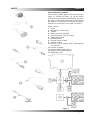
Interconnecting cables (figure 3) are used to join the
engine (1), throttle (3), battery (4), via the marine
junction box (2), to the instrument panel(s) (5). Cables
are made in a 12m length as standard, 3, 6 & 9 lengths
are optional. If a longer cable is required it should be
ordered as a special item, to be made in one piece.
Figure 2 shows:
1. Engine.
2. MJB (Marine Junction Box).
3. Throttle.
4. Battery (customer supplied).
5. Instrument panel - main or auxillary.
6. MMPD, digital panel.
7. Keyswitch panel.
8. Harness, engine to MJB.
9. Harness, throttle.
10. Harness, main or auxillary panel, J1939 requires
tee connector.
11. Harness, keyswitch.
12. Harness, MMPD (digital panel).
13. Battery lead (customer supply).
14. Master/slave lead.
Figure 2
Figure 3
Page 25
Chapter 8
N40475
Instrument panels
Three types of panel are available, providing different
levels of instrumentation.
Main panel
• 12 or 24 volt operation from same panel.
• IP 65 rated from front facia, switches/gauges IP67
rated.
The ‘Main Panel’ shown in Figure 4 is 250mm x
175mm and includes:1. Tachometer
2. Engine hours/fault code display
3. Warning light
4. Oil pressure gauge
5. Warning light
6. Water temperature gauge
7. Warning light
8. Warning lamp
9. Diagnostic lamp
10. Engine crank
11. Voltage gauge
12. Warning light
13. Keyswitch on/off
14. Engine stop switch
15. Panel illumination
The cutout dimensions are shown below the panel
illustration.
Page 26
Figure 4
N40475
Chapter 8
Auxiliary panel
• 12 or 24 volt operation from same panel.
• IP 65 rated from front facia, switches/gauges IP67
rated.
The ‘Auxiliary panel’ shown in Figure 5 is 180mm x
140mm and includes:1. Tachometer
2. Engine hours/fault code display
3. Warning light
4. Warning lamp
5. Engine crank
6. Keyswitch on/off
7. Diagnostic lamp
8. Engine stop switch
9. Panel illumination
The cutout dimensions are shown below the panel
illustration.
Figure 5
Page 27
Chapter 8
N40475
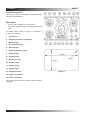
Mini Marine Power Display (MMPD)
digital panel
• Single engine support.
• Displays engine parameters and fault codes with
audible alarm.
• 5 display screens.
• High resolution display 320 X 240 DPI.
• Transflective screen improves readability by
reflecting more or less light conditions as ambient
light changes.
• Display brightness fully adjustable.
• Operates on 12 or 24 V systems.
• Supports several languages - English, German,
French, Dutch, Portuguese, Norwegian and
Italian.
• IP 67 rated.
The ‘Digital panel’ shown in Figure 6 is 150mm x
103mm and includes:1. Display:
2. Screen illumination
3. Alarm mute
4. Scroll forward button
5. Scroll back button
The cutout dimensions are shown below the panel
illustration.
Page 28
Figure 6
N40475
Chapter 8
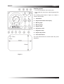
Keyswitch panel
The ‘Keyswitch panel’, used with the digital panel,
is shown in figure 7 and is 110mm x 90mm and
includes:1. Engine crank
2. Warning lamp
3. Diagnostic lamp
4. Engine stop switch
5. Keyswitch on/off
The cutout dimensions are shown below the panel
illustration.
Figure 7
Page 29
Chapter 8
N40475
Possible panel configurations.
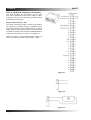
A variety of panels may be run simultaneously, in any
of the combinations as shown in figure 8.
1. Power supply.
2. Cable or electronic throttle and gearbox control
options.
3. Main panel.
4. Auxiliary panel.
5. Mini Marine Power Dispaly (MMPD) digital panel.
6. Keyswitch panel.
Figure 8
Page 30
N40475
Chapter 8
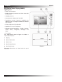
Mini Marine Power Dispaly (MMPD)
instructions
The Mini Marine Power Display (MMPD) provides
current engine and transmission operating data.
The screen can be customized to display various
engine parameters and Multi Station Control System
(MSCS) information. The MMPD software has been
redesigned to include MSCS functions.
Information screens
There are two information screens available, the
System Information screen and the Control System
Information screen (figure 9). Pressing the button
labelled Menu will display the System Information
screen or the control system Information screen.
The System Information screen is the first screen
displayed by default, however the MMPD will retain
which information screen was displayed last until a
power-off/reset.
System information screen
The System Information screen will display the current
User Name, Software Version, ROM Bootloader
Software Version, Unit Serial Number, Unit Location,
Engine Location, Display Units, and Vessel Speed
Units.
Figure 9
Pressing the button labelled Menu will display the
System Information menu screen. On this screen, the
button function is re-defined as shown on the right
side of the screen, see figure 10. If a diagnostic code
is active and the diagnostic code window is on screen,
the button actions return to their normal definitions.
Pressing the up or down arrow button will cause the
top menu item (labeled Change Screen) to scroll
through the items to be changed (Change Screen,
Change User, Change Unit Location, Change Display
Units, and Change Vessel Speed Units) and cause
the selected data to be displayed in reverse video.
Figure 10
Pressing the alarm button will cause the specified
parameter to scroll through each available value (i.e.
Change Vessel Speed would scroll through Knots,
MPH, and KPH). Pressing the button labelled Exit will
return the display to the System Information screen
and save any changed data to non-volatile memory.
Page 31
Chapter 8
N40475
Change screen
Pressing the alarm button will cause the Control
System Information screen to be displayed. This
option is only available if the MMPD has detected a
Powertrain Control Processor (PCP) on the CAN data
link.
Change user
Pressing the alarm button will cause the displayed
User Name text to scroll through the available user
names.
Change unit location
Pressing the alarm button will cause the displayed
Unit Location text to scroll through the available
location selections.
The vessel locations that are available are: Bridge,
Port Wing, Starboard Wing, Tower, Engine Room, Aft
Station, Fly Bridge, and Bow Station.
Change display units
Pressing the alarm button will cause the displayed
Display Units text to scroll through the available units
selections (English and Metric).
Change vessel speed units
Pressing the alarm button will cause the displayed
Vessel Speed Units text to scroll through the available
units selections (Knots, MPH, and KPH).
Change system information screen
The Control System Information screen will only be
displayed if a Powertrain Control Processor (PCP)
is detected on the data link. This screen will display
the PCP software part number, Troll Mode, Troll Set
Engine Speed, Engine Sync Master, Active Station
Location, active Station Button Status, and Active
Station Lamp Status. Pressing the button labelled
Menu will display the screen shown in figure 11.
On this screen the button functions are re-defined
as shown on the right side of the screen. However,
in the presence of a diagnostic code window button
actions return to their normal definitions. Pressing
the up or down arrows will cause the top menu item
(labeled Change Screen) to scroll through the items
to be modified (Change Screen, Change Troll Mode,
Change Set Speed, Change Sync Master, and Change
Station Location) and cause the selected data to be
displayed in reverse video. Pressing the alarm button
will cause the specified parameter to scroll through
each available value. Pressing the button labeled
Exit will return the display to the Control System
Information screen and transmit any changed data
items to the PCP.
Page 32
Figure 11
N40475
Chapter 8
Change screen
Pressing the alarm button will cause the System
Information screen to be displayed.
Change troll mode
Pressing the alarm button will cause the displayed
Troll Mode to scroll through the available troll modes
(Traditional and Intelli-Troll).
Figure 12
Change troll speed
Selecting Change Troll Set Speed (as figure 12) will
display the following screen. Pressing + will increase
the set speed by 1 rpm and pressing – will decrease
the set speed by 1 rpm. Pressing Save will cause
the MMPD to send the data to the PCP (and exit the
screen), and pressing Cancel will cause the MMPD to
exit the screen without sending any data to the PCP.
Change engine sync master
Pressing the alarm button will cause the displayed
Engine Sync Master to scroll through the available
sync master selections (PORT and STBD).
Active station location
Displays the Active Station Location (Bridge, Port
Wing, Starboard Wing, Tower, Engine Room, Aft
Station, Fly Bridge, and Bow Station). If the PCP
reports that there is no active station, then the MMPD
will display NONE in the Active Station Location field.
Button status indicator
The Station Button Status indicators display the button
status as read by the active control station.
• SA – Activate Station Button Status
• SVM – Slow Vessel Mode Button Status
• SYC – Engine Synchronization Button Status
• N – Idle (Neutral) Lockout Button Status
• TR – Trolling Mode Button Status
Lamp status indicator
The Station Lamp Status indicators display the
commanded lamp status from the active control
station.
• SA – Activate Station Lamp Status
• SVM – Slow Vessel Mode Lamp Status
• SYC – Engine Synchronization Lamp Status
• N – Idle (Neutral) Lockout Lamp Status
• TR – Trolling Mode Lamp Status
Page 33
Chapter 8
N40475
Vessel status bar
The status indicators are shown across the top of
the screen in reverse video and are only available on
parameter screens, except for the diagnostic icon,
which is shown on all screens.
Status items (figure 13)
1. Active diagnostic status of active station location.
2. Slow Vessel Mode (SVM) status.
3. Gear position
4. Troll mode status.
5. Engine synchronization status.
The Diagnostic icon overrides the Active Station
Location when there is an active diagnostic
condition.
Parameter
Status
Display Text
Slow Vessel
Mode (SVM)
SVM active
SVM inactive
SVM
No text
displayed
Gear position
Forward
AHEAD
Neutral
NEUTRAL
Reverse
ASTERN
Gear Lockout
Active
Gear L/O
Troll Mode
Troll active
Troll inactive
TROLL
No text
displayed
Engine sync
mode
Synchronized
PORT
SYNC-P
Synchronized
STBD
SYNC-S
PORT Master
Sync cruise
active
CRUISE-P
STBD Master
Sync cruise
active
CRUISE-S
Sync not active
No text
displayed
bridge
PORT Wing
STBD Wing
Tower
Engine room
Aft station
Fly bridge
Bow station
BRIDGE
PORT WING
STBD WING
TOWER
ENG ROOM
AFT STATION
FLY BRIDGE
BOW
STATION
Active station*
* If there is an active diagnostic, the word DIAGNOSTIC will be
displayed in place of the active station location.
Page 34
Figure 13
N40475
Chapter 8
Cables required
Where Used: Connects the PCP and MMPD displays
into the J1939 data link.
The J1939 data link (item 1 figure 14) can not exceed
40 meters (131 ft.).
Requires:
MMPD drop cable
Tee to Tee cable
6-pin Tee
Termination resistor
Figure 14
Termination resistor (figure 15)
Used to terminate the ends of a data link run. Two
termination resistors required
Tee connector (figure 16)
Used to connect tee to tee cables.
CAN Data Link
SAE J1939-15: Unshielded twisted pair.
The CAN network operates at 250 Kb/sec, it follows
J1939-15 protocol.
J1939-15
Figure 15
Maximum Drops (nodes)
10
Maximum Cable Stub Length
3M
Maximum Cable Stub Length for
service connector
2.66M
Maximum Bus Length
40M
Shielded Cable
NO
Figure 16
Page 35
Chapter 8
N40475
Marine Junction Box (MJB)
• Provides circuit protection for the ECM and other
components connected to the on board monitoring
and control systems.
• Stand alone
application.
junction
box
for
any
marine
• Used with various lengths of wiring harness for
easier installation.
• Available for single (figure 17 item 1) or twin (figure
10 item 2) engine installations.
Inside the twin engine installation junction box,
there are two separate wiring sections, one for the
port system and a second for the starboard system.
These sections provide the interconnection points for
engine power and vessel control and monitoring. The
Marine Junction Box also provides circuit protection
for the ECM, keyswitch, and the other components
connected to the vessel control system.
Figure 17
Page 36
N40475
Chapter 8
Single engine MJB features and
mounting details
1. Breakers.
2. Throttle.
3. Expansion.
4. ECM.
5. J1939.
6. Key/alarm.
7. Custom.
8. Throttle synchronization panel.
9. PDL connector to EMS engine vision or service
tool.
10. Power for the power train control processor (not
used).
11. Connection for battery + battery.
12. Connection for battery - battery.
Figure 18
Page 37
Chapter 8
N40475
Twin engine MJB features and mounting
details
1. Breakers.
2. Custom (port side).
3. Key/alarm (port side).
4. J1939 (port side).
5. ECM (port side).
6. Expansion (port side).
7. Throttle (port side).
8. Throttle (starboard side).
9. Expansion (starboard side).
10. ECM (starboard side).
11. J1939 (starboard side).
12. Key/alarm (starboard side).
13. Custom (starboard side).
14. Throtlle synchronization panel
15. PDL connector to service tool.
16. Power for the power train control processor (not
used).
17. Connection for battery + battery.
18. Connection for battery - battery.
Figure 19
Page 38
N40475
Chapter 8
Power connections
1. Marine junction box.
2. Battery reverse isolator.
3. Batteries
4. Minus battery bus bar.
4 Stations
8 Stations
Cable
length*
12 volt
24 volt
12 volt
24 volt
5ft.(1.52m)
10 AWG
12AWG
6AWG
10 AWG
10ft
(3.05m)
10 AWG
12 AWG
6 AWG
10 AWG
15ft
(4.57m)
8 AWG
10 AWG
4 AWG
8 AWG
25ft
(7.62m)
6 AWG
8 AWG
2 AWG
6 AWG
30ft
(9.14m)
4 AWG
8 AWG
1 AWG
4 AWG
*Refer to ABYC rules E-11 for AC & DC electrical systems
on boats for more details.
Figure 20
Note: Perkins recommends installing two +battery
and two -battery cables from the reverse isolator to the
MJB and from the reverse isolator to the batteries.
Current requirements 12 or 24 vdc
system
The typical current draw for the MSCS with a twin
engine installation with 4 control stations is 30 amps .
The current draw for a twin engine installation with 8
control stations is 62 amps .
ECM port or starboard interface
connectors
The MJB provides two interface connectors, one for
the port engine and one for the starboard engine,
which connect to the J61 customer connector. The
connections are to interface with the ECM customer
connector and provide battery power, switched inputs
and data link signals to and from the ECM. The
pin out is the same for both the port and starboard
connectors .
Grounding the battery negative
It is recommended that the battery negative busbar
should be grounded as close as possible to the
battery, by a substantial connection to the bonding
system within the boat. This will reduce the likelihood
of interference between items of electrical and
electronic equipment fitted to the boat.
Page 39
Chapter 8
N40475
Port or starboard expansion connectors
The MJB provides two connectors, one for port
and one for starboard, which will be used for future
expansion. The pin out is the same for both the port
and starboard connectors.
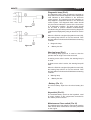
Starter Interlock (Pins 1 & 2)
The starter interlock provides a means of preventing
the engine from starting through a switched circuit.
The starter interlock may be wired through a neutral
safety switch or other similar device. If no such device
is installed, a jumper wire should be installed between
expansion connector pins 1 and 2 as in figure 22.
Figure 23 shows a neutral safety switch (figure 16
item 1), between the starter interlock pins 1 and 2.
Figure 21
Figure 22
Figure 23
Page 40
N40475
Chapter 8
Diagnostic lamp (Pin 2)
Figure 24
The diagnostic lamp, figure 24 alerts the operator to
the presence of an active diagnostic code. A diagnostic
code indicates a fault condition in the electronic
control system. The operator uses this indication to
help diagnose component failures in the electronic
control system. The diagnostic flash codes should
only be used to indicate the nature of the occurrence
of a diagnostic condition. The flash codes should
not be used to perform detailed troubleshooting.
Troubleshooting should be performed using diagnostic
codes that are displayed by using an electronic service
tool.
When the ECM is energized (keyswitch turned ON),
the warning lamp will turn on for five seconds. Then
the lamp will turn off unless the ECM detects a warning
condition.
1. Diagnostic lamp.
Figure 25
2. + Battery bus bar.
Warning lamp (Pin 1)
The warning lamp figure 25 is used to alert the
operator that an engine event has occurred.
A warning event code is active; the warning lamp is
on solid.
A derate event code is active; the warning lamp will
flash.
When the ECM is energized (keyswitch turned ON),
the warning lamp will turn on for five seconds. Then
the lamp will turn off unless the ECM detects a warning
condition.
1. Warning lamp
2. + Battery bus bar.
- Battery (Pin 11)
The minus battery input from the minus battery bus
bar
Keyswitch (Pin 12).
The switched battery input from the keyswitch, used
to supply +battery to the components connected to
the custom panel connector .
Maintenance Clear switch (Pin 16)
The mainitenance clear switch is required to reset the
PM1 interval after manitenance has been performed
on the engine.
Page 41
Chapter 8
N40475
Cold start system
Cold start data 12V and 24V
Temperature
Battery type with oil viscosity used
20W
5°C
15W
10W
5W
0W
F
-25°C
2XB
-40°C
Min average
cranking speed
rev/min
Start aid type
2XE
Total battery
voltage nominal
Glow plugs
130
12V
Glow plugs
100
12V
Glow plugs and
block heating
100
12V
Battery performance
Battery Selection Tables By Engine-Results For Bare Engines based on min required speed of 100 rpm
Engine tested with 75% state of charge batteries and 1.7 mω cable resistance
Starter information
Temperature & oil grade without glow plugs
Voltage
Starter type
-5OC 15W40
12V
Iskra AZF
950
24V
Iskra AZF
650
Commercial reference number Perkins code
643
647
069
655
621
A
B
D
E
F
Battery minimum performance
BS EN 50342 (1)
SAE J537 (BCI) (2)
DIN 43539 (3)
440
510
340
570
860
640
700
540
760
900
400
465
300
490
505
(1) Voltage no less that 7,5V after 10 seconds, 6V after 90 seconds at -18OC (0OF) across each 12V battery.
(2) Voltage no less than 7,2V after 30 seconds at -18OC (0OF) across each 12V battery.
(3) Voltage no less than 6,0V after 150 seconds at -18OC (0OF) across each 12V battery.
Battery to starter lead resistance
The resistance of the lead(s) used between the battery/batteries and the starter motor must not be more than
0.0017 ohms for 12V systems and 0.0034 ohms for 24V systems. More detailed information on types of battery
is available from the Wimborne Marine Power Centre.
Page 42
N40475
Chapter 8
Battery isolator switches
A switch should be fitted in the positive lead to the
starter, as close to the battery as is convenient. The
switch should be suitable for a momentary current of
at least 950 Amps.
Zinc Anode bonding system
Caution: The engine may be damaged by electrolytic
corrosion if the correct bonding procedure is not
adopted. Please read the guidelines below carefully.
Electrolytic corrosion within the engine cooling system
and transmission can be much reduced or eliminated
by bonding the engine to a Zinc anode which is used
to protect through the hull metal fittings and other
metal components that are in contact with sea water.
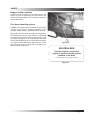
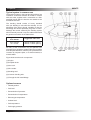
The engine is fitted with a stud (figure 26 item 1) that
may be used for this purpose and is identified by a
label as shown in figure 27.
Figure 26
BOATBUILDER
Use this stud to connect the
engine to the Zinc Anode system
installed in the boat.
(For further details see the Installation Manual)
Figure 27
Page 43
Chapter 8
N40475
Typical system in common use
The bonding system in the boat should provide a low
resistance connection between all metals in contact
with sea water, together with a connection to a Zinc
sacrificial anode which is fixed to the outside of the
hull below sea level.
The bonding should consist of heavy stranded
wire (not braiding or wire with fine strands). It is an
advantage if the wire is tinned. Insulation is also an
advantage and should preferably be green in colour.
Although the current carried by the bonding system
will not normally exceed 1 amp, the cable sizes should
be generous as shown in the table below:
Length of run to
Zinc Anode
Suggested cable size
Up to 30 feet
30 - 40 feet
7 strand / 0.85mm (4mm2)
7 strand / 1.04mm (6mm2)
As many of the connections may be splashed with
sea water they should be soldered wherever possible
and clamped elsewhere, with the joint protected from
corrosion by neoprene paint, or a similar material, to
exclude water.
Figure 28 shows the main components.
(1) Engine.
(2) Propeller shaft.
(3) Sea cock.
(4) Zinc anode.
(5) Bonding stud.
(6) Common bonding wire.
(7) Through the hull metal fittings.
Optional sensors
• Throttle position.
• Fuel level.
• Transmission oil pressure.
• Transmission oil temperature.
• Exhaust gas temperature.
• Coolant level.
• Fuel temperature
• Fuel supply pressure
Page 44
Figure 28
N40475
Page 45
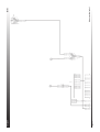
Engine wiring harness overview
Chapter 8
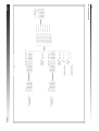
Page 46
Chapter 8
Panel harness overview
N40475
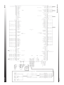
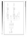
Wiring diagrams
N40475
Page 47
Engine wiring harness 1
Chapter 8
Page 48
Chapter 8
Engine wiring harness 2
N40475
N40475
Page 49
Engine panels 1
Chapter 8
Page 50
Chapter 8
Interconnecting leads 1
N40475
N40475
Page 51
Master/slave option, port
Chapter 8
Page 52
Chapter 8
Marine junction box
N40475
N40475
Page 53
Master/slave option, starboard
Chapter 8
Page 54
Chapter 8
Interconnecting leads 2
N40475
N40475
Page 55
Engine panels 2
Chapter 8
Page 56
Chapter 8
N40475
N40475
Chapter 9
Engine controls
It is recommended that a Morse single lever system
is used to control engine speed and gearbox
engagement.
1. Throttle lever.
2. Anchor for Morse 33C cable.
3. Morse 33C cable.
4. Idle position.
5. Run position
Figure 1
Page 57
Chapter 9
Page 58
N40475
N40475
Chapter 10
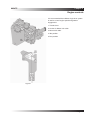
Provision for power take-off
Warning! Remove all paint traces from the mating
faces before assembly.
Fit the power take-off shaft, (figure 1 item 1) using
bolts (figure 1 item 2) and tighten to a final torque of
84 lb.ft. (115Nm)
Fit the key (figure 1 item 3) to the power take-off shaft
.
For axial drives
Figure 1
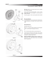
For axial drives it is recommended that a flexible drive
coupling between the engine and any given load is
used.
For belt drives
Standard options are:Either a 5” ‘A’ section pulley with three grooves (figure
2 item 1) and a taper lock (figure 2 item 2).
or
A 5” ‘B’ section pulley with two grooves (figure 3).
In this case the maximum power which can be taken
will be limited by the belts, and it will be necessary to
calculate for marginal applications.
Figure 2
Caution: Additional inertia must not be added to the
P.T.O. shaft without specialist advice. Consult your
distributor if you need advice about non-standard
drive arrangements.
Figure 3
Page 59
Chapter 10
N40475
Polar diagram
This diagram shows the loading capability of the front
of the crankshaft.
The load angle, when viewed from the front of the
engine, is measured clockwise, with 0° aligned to
TDC.
Overhung load (Newtons) is directed radially outwards
from the centre of the diagram.
Figure 4
Page 60
N40475
Chapter 11
Calorifier and block heater connections
Calorifier
Fittings are available to allow a calorifier to be
connected to the engine, as shown in figure 1. The
fittings may be ordered as part of the engine assembly,
or as loose parts to be fitted later.
The hose connections to the calorifier must be of a
radiator or heater hose quality and 1/2” bore, and
must be installed so that chafing will not occur.
(1) Supply to calorifier.
(2) Return from calorifier.
Block heater connection points
A mains powered cylinder block heater may be fitted
to keep the engine warm when the boat is stored in
low temperatures. A suitable heater may be ordered
as part of the engine assembly, or may be fitted later.
Figure 2 shows the connection point. The core plug
in the position shown on the engine block is removed
and the block heater fitted and secured with a bolt.
Figure 1
If the heater is ordered at the same time as the engine,
it can be attached to the engine.
Figure 2
Page 61
Chapter 11
Page 62
N40475
N40475
Chapter 12
Reference data
Basic data
M300C
M250C
Rated power ......................................... 300 hp (225 kW). ..................................250hp (186 kW)
Rated engine speed ..................................................................2400 rpm.
Number of cylinders......................................................................... 6.
Cylinder arrangement .................................................................. In-line.
Cycle...........................................................................................4 Stroke.
Induction System ......................................................... Turbocharged aftercooling.
Bore ...................................................................................... 105 mm (4.13”).
Stroke ................................................................................... 127mm (5.00”).
Compression Ratio ...................................................................... 16.2:1.
Cubic Capacity ....................................................................6.6 Litre (365 in3).
Valves per cylinder .......................................................................... 2.
Direction of Rotation .............................................Anti-clockwise viewed from flywheel.
Firing Order ........................................................................... 1, 5, 3, 6, 2, 4.
Total Weight (wet) ............................. 738 kg (1627 lbs) engine only including alternator and starter.
Cooling
Cooling System ...................................The coolant shown is mandatory for use in all climates to
ensure that adequate levels of corrosion inhibitor are present.
It will give frost protection to -37OC.
Coolant .................................................................... 50% inhibited ethylene glycol or
50% inhibited propylene glycol with 50% fresh clean water.
Fresh Water Flow ................................................................TBA at 2400 rpm.
Coolant pump speed and method of drive............................1:1 Gear Driven.
System Capacity...............................................................26 litres (5.7 gallons).
Pressure cap setting .............................................................. 50 kPa (7 psi).
Sea water pump type........................................................ Gear driven full cam.
Sea water suggested inlet .....................................32 mm Bore (1.25”) hose diameter.
Sea cock ......................................................................... Full flow 32 mm (1.25”)
Strainer ....................................... Auxiliary water strainer must be included in suction side of the circuit
Maximum sea water temperature ........................................... 39OC (102OF)
Sea water flow ...................................................... 141 l/min (31 galls/min) @ 2400rpm
Page 63
Chapter 12
N40475
Fuel system
Recommended fuel .............................................. DIN E 590 DERV (class A-F & 0-4)
BS2869 Class A2 (Off highway, gas oil, red diesel)
ASTM D975-91 Class 1-1DA & Class 2-2DA
JIS K2204 (1997) Grades 1, 2, 3 & Special grade 3
JP7/F63, JP8, JP5 Jet A/A1
Diesel fuel mix with 5 vol% RME in accordance with proposal 51606
JIS K2203
Fuel injection pump .......................... in-line with boost control and electric.stop (energised to stop)
Fuel lift pump ...........................................................................plunger type
Fuel feed pressure (static) ..............................................0.3 to 0.6 bar (5 to 8psi)
Governor type .......................................................................... Mechanical.
Pipe size:
• Supply - outside diameter ................................................... 10mm (0.394”)
• Supply - bore ...................................................................... 8.4mm (0.331”)
• Return - outside diameter .................................................... 10mm (0.394”)
• Return - bore ...................................................................... 8.4mm (0.331”)
Maximum lift pump lift ....................................... 1.8 m (6ft) to bottom of tank suction pipe.
Maximum fuel lift pump ................................... 127 mm (5 inches) Hg depression at inlet.
Fuel consumption at full ............................................. 56.6 l/hr (12.4galls/hr)power.
Air intake
Combustion airflow ........................................................ 14.8m3 /min (524ft3/min).
Maximum engine compartment ................................................... 60OC.
air temperature.
Maximum air temperature at......................................................... 52OC.
engine inlet
Ventilation - maximum engine ......................................... 125 mm WG (5” WG).
room depression
Suggested ventilation airflow ..........................................30m3 /min (1050ft3/min).
including combustion air
Minimum cross section ..........................................910cm2(142sq ins) for hot climates.
of air duct (per engine).
455cm2(71sq ins) for temperate climates.
Exhaust
Exhaust gas flow ...........................................................43.1m3 /min (1520ft3/min)
Maximum restriction measured ....................................................15kPa
within (305mm) 12” of turbocharger outlet .
Recommended pipe bore (wet exhaust) ................................ 127mm (5.0”)
Recommended pipe bore (dry) ............................................. 101.6mm (4.0”)
Minimum rise from sea level to ............................................... 203mm (8.0”)
exhaust outlet centre-line
Page 64
N40475
Chapter 12
Lubricating system
Recommended lubricating oil ..................................................... API CI-4
Sump capacity maximum ................................................. 15 litres (3.3 gallons)
Maximum operational angle .......................20O nose up. Heel 25O constant, 35O intermittent
Oil pressure in operating ............................................. 2.5 to 3.5 bar (36 to 50 psi)
speed range (steady state)
Electrical system
Alternator ............................................................. 55 amp (28 volt) or 100 amp (14 volt)
Starter type ...............................................................................12V or 24V
Number of teeth in flywheel ............................................................126
Number of teeth on starter...............................................................10
Cold start limits
Minimum cold start temperature (with aid) .............................-40OC (-40OF)
Page 65
Chapter 12
Page 66
N40475
N40475
Chapter 12
Reference data
Basic data
M216C
M190C
Rated power ......................................... 300 hp (225 kW). ..................................250hp (186 kW)
Rated engine speed ................................... 2400 rpm. .............................................2100 rpm
Number of cylinders......................................................................... 6.
Cylinder arrangement .................................................................. In-line.
Cycle...........................................................................................4 Stroke.
Induction System ......................................................... Turbocharged aftercooling.
Bore ...................................................................................... 105 mm (4.13”).
Stroke ................................................................................... 127mm (5.00”).
Compression Ratio ...................................................................... 16.2:1.
Cubic Capacity ....................................................................6.6 Litre (365 in3).
Valves per cylinder .......................................................................... 2.
Direction of Rotation .............................................Anti-clockwise viewed from flywheel.
Firing Order ........................................................................... 1, 5, 3, 6, 2, 4.
Total Weight (wet) ............................. 738 kg (1627 lbs) engine only including alternator and starter.
Cooling
Cooling System ...................................The coolant shown is mandatory for use in all climates to
ensure that adequate levels of corrosion inhibitor are present.
It will give frost protection to -37OC.
Coolant .................................................................... 50% inhibited ethylene glycol or
50% inhibited propylene glycol with 50% fresh clean water.
Fresh Water Flow ................................. TBA at 2400 rpm. .................................TBA at 2100 rpm
Coolant pump speed and method of drive............................1:1 Gear Driven.
System Capacity...............................................................26 litres (5.7 gallons).
Pressure cap setting .............................................................. 50 kPa (7 psi).
Sea water pump type........................................................ Gear driven full cam.
Sea water suggested inlet .....................................32 mm Bore (1.25”) hose diameter.
Sea cock ......................................................................... Full flow 32 mm (1.25”)
Strainer ....................................... Auxiliary water strainer must be included in suction side of the circuit
Maximum sea water temperature ........................................... 39OC (102OF)
Sea water flow ........................141 l/min (31 galls/min) @ 2400rpm ...141 l/min (31 galls/min) @ 2100rpm
Page 67
Chapter 12
N40475
Fuel system
Recommended fuel .............................................. DIN E 590 DERV (class A-F & 0-4)
BS2869 Class A2 (Off highway, gas oil, red diesel)
ASTM D975-91 Class 1-1DA & Class 2-2DA
JIS K2204 (1997) Grades 1, 2, 3 & Special grade 3
JP7/F63, JP8, JP5 Jet A/A1
Diesel fuel mix with 5 vol% RME in accordance with proposal 51606
JIS K2203
Fuel injection pump .......................... in-line with boost control and electric.stop (energised to stop)
Fuel lift pump ...........................................................................plunger type
Fuel feed pressure (static) ..............................................0.3 to 0.6 bar (5 to 8psi)
Governor type .......................................................................... Mechanical.
Pipe size:
• Supply - outside diameter ................................................... 10mm (0.394”)
• Supply - bore ...................................................................... 8.4mm (0.331”)
• Return - outside diameter .................................................... 10mm (0.394”)
• Return - bore ...................................................................... 8.4mm (0.331”)
Maximum lift pump lift ....................................... 1.8 m (6ft) to bottom of tank suction pipe.
Maximum fuel lift pump ................................... 127 mm (5 inches) Hg depression at inlet.
Fuel consumption at full ............................................. 56.6 l/hr (12.4galls/hr)power.
Air intake
Combustion airflow ........................................................ 14.8m3 /min (524ft3/min).
Maximum engine compartment ................................................... 60OC.
air temperature.
Maximum air temperature at......................................................... 52OC.
engine inlet
Ventilation - maximum engine ......................................... 125 mm WG (5” WG).
room depression
Suggested ventilation airflow ..........................................30m3 /min (1050ft3/min).
including combustion air
Minimum cross section ..........................................910cm2(142sq ins) for hot climates.
of air duct (per engine).
455cm2(71sq ins) for temperate climates.
Exhaust
Exhaust gas flow ...........................................................43.1m3 /min (1520ft3/min)
Maximum restriction measured ....................................................15kPa
within (305mm) 12” of turbocharger outlet .
Recommended pipe bore (wet exhaust) ................................ 127mm (5.0”)
Recommended pipe bore (dry) ............................................. 101.6mm (4.0”)
Minimum rise from sea level to ............................................... 203mm (8.0”)
exhaust outlet centre-line
Page 68
N40475
Chapter 12
Lubricating system
Recommended lubricating oil ..................................................... API CI-4
Sump capacity maximum ................................................. 15 litres (3.3 gallons)
Maximum operational angle .......................20O nose up. Heel 25O constant, 35O intermittent
Oil pressure in operating ............................................. 2.5 to 3.5 bar (36 to 50 psi)
speed range (steady state)
Electrical system
Alternator ............................................................. 55 amp (28 volt) or 100 amp (14 volt)
Starter type ...............................................................................12V or 24V
Number of teeth in flywheel ............................................................126
Number of teeth on starter...............................................................10
Cold start limits
Minimum cold start temperature (with aid) .............................-40OC (-40OF)
Page 69
Chapter 12
Page 70
N40475
California
Proposition 65 Warning
Diesel engine exhaust and some of its constituents are
known to the State of California to cause cancer, birth
defects, and other reproductive harm.
®
Wimborne Marine Power Centre
22 Cobham Road, Ferndown Industrial Estate, Wimborne, Dorset, BH21 7PW, England.
Tel: +44 (0)1202 893720, Fax: +44 (0)1202 851700
E-mail: [email protected], Web: www.Perkins-Sabre.com