1
N40475
Chapter 8
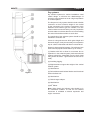
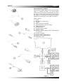
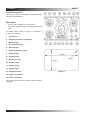
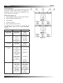
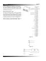
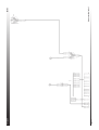
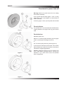
Diagnostic lamp (Pin 2)
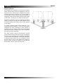
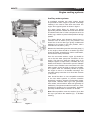
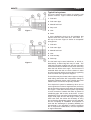
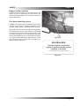
Figure 24
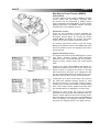
The diagnostic lamp, figure 24 alerts the operator to
the presence of an active diagnostic code. A diagnostic
code indicates a fault condition in the electronic
control system. The operator uses this indication to
help diagnose component failures in the electronic
control system. The diagnostic flash codes should
only be used to indicate the nature of the occurrence
of a diagnostic condition. The flash codes should
not be used to perform detailed troubleshooting.
Troubleshooting should be performed using diagnostic
codes that are displayed by using an electronic service
tool.
When the ECM is energized (keyswitch turned ON),
the warning lamp will turn on for five seconds. Then
the lamp will turn off unless the ECM detects a warning
condition.
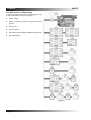
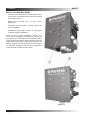
1. Diagnostic lamp.
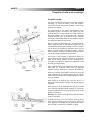
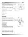
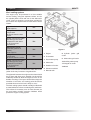
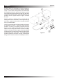
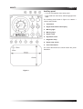
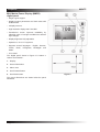
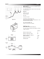
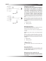
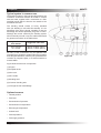
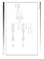
Figure 25
2. + Battery bus bar.
Warning lamp (Pin 1)
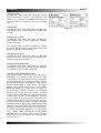
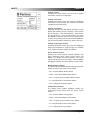
The warning lamp figure 25 is used to alert the
operator that an engine event has occurred.
A warning event code is active; the warning lamp is
on solid.
A derate event code is active; the warning lamp will
flash.
When the ECM is energized (keyswitch turned ON),
the warning lamp will turn on for five seconds. Then
the lamp will turn off unless the ECM detects a warning
condition.
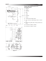
1. Warning lamp
2. + Battery bus bar.
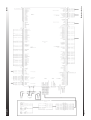
- Battery (Pin 11)
The minus battery input from the minus battery bus
bar
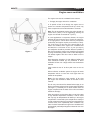
Keyswitch (Pin 12).
The switched battery input from the keyswitch, used
to supply +battery to the components connected to
the custom panel connector .
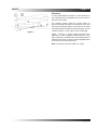
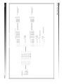
Maintenance Clear switch (Pin 16)
The mainitenance clear switch is required to reset the
PM1 interval after manitenance has been performed
on the engine.
Page 41