1
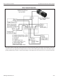
Basler Cameras (Older Terminal Blocks)
M-Series Processor and Camera Guide
CAMERAS.
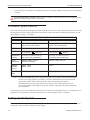
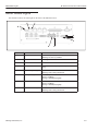
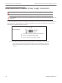
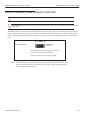
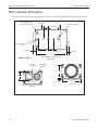
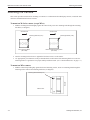
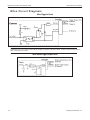
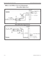
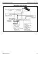
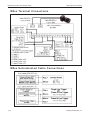
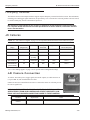
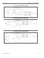
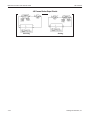
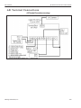
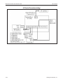
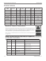
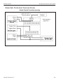
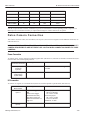
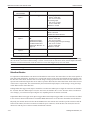
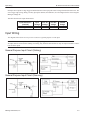
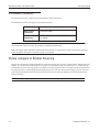
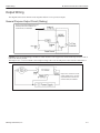
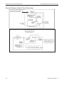
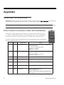
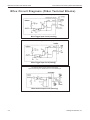
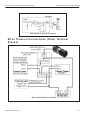
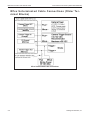
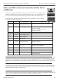
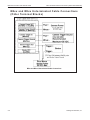
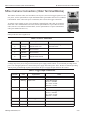
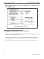
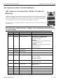
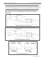
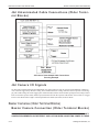
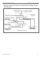
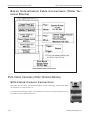
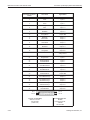
Camera power, trigger signal, and strobe trigger can be connected to the camera using one of two methods: a terminal
block and cable or an unterminated cable only. To use a terminal block (248-0141), you must also use the optional Hirose
12-pin to HD-15 camera cable (606-0673-xx). To connect the camera using an unterminated cable, use the optional
Hirose 12-pin to unterminated cable (part number 606-0671-xx).
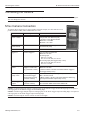
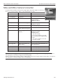
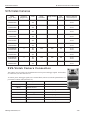
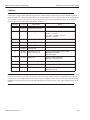
Terminal
Color
1
2
Wht/Blu
Wht/Org
3
Wht/Brn
Signal Name
Notes
Camera Power Ground
Camera Power Ground
See Note 1 below
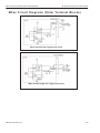
Camera Trigger In
0 to +24 VDC recommended
Off: 0 to + 1.4 VDC
On: +2.2 to + 12VDC; 5 to 15 ma
Maximum: +30 VDC
4
Brn/Wht
DO NOT USE
5
Wht/Grn
Camera Trigger Ground
6*
Wht/Gry
Strobe Trigger Out
7
Gry/Wht
DO NOT USE
8
9
Blu/Wht
Org/Wht
Camera Power VCC
Camera Power VCC
+12 VDC recommended @ 500 mA Max
Maximum: +13.2 VDC
See Note 1 below
10
Grn/Wht
Strobe VCC
Based on strobe requirement
Maximum: +30 VDC; 50 ma
11
Red/Blu
DO NOT USE
12
Blu/Red
DO NOT USE
13*
None
Strobe Output Ground
(*Block contains 270 Ohm 2W resistor between
terminals 6 and 13)
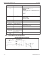
NOTE 1: Pins 1 and 2 are tied together inside of the camera. Pins 8 and 9 are tied together inside of the camera. To avoid
a voltage drop when there are long wires between your power supply and the camera, we recommend that you provide
camera power VCC through separate wires between your power supply and pins 8 and 9 on the camera. We also recommend that you provide camera power ground through separate wires between your power supply and pins 1and 2 on the
camera.
Datalogic Automation, Inc.
6-20