1
N40475
Chapter 10
Provision for power take-off
Warning! Remove all paint traces from the mating
faces before assembly.
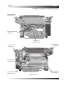
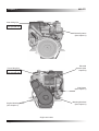
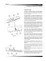
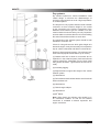
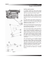
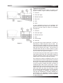
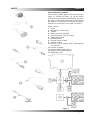
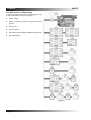
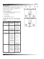
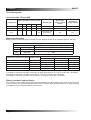
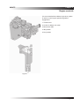
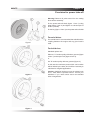
Fit the power take-off shaft, (figure 1 item 1) using
bolts (figure 1 item 2) and tighten to a final torque of
84 lb.ft. (115Nm)
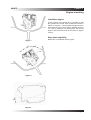
Fit the key (figure 1 item 3) to the power take-off shaft
.
For axial drives
Figure 1
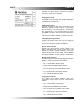
For axial drives it is recommended that a flexible drive
coupling between the engine and any given load is
used.
For belt drives
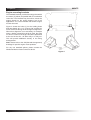
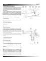
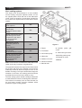
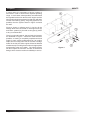
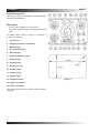
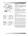
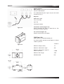
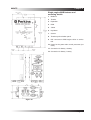
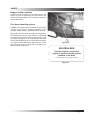
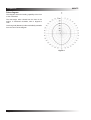
Standard options are:Either a 5” ‘A’ section pulley with three grooves (figure
2 item 1) and a taper lock (figure 2 item 2).
or
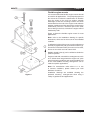
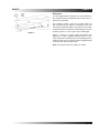
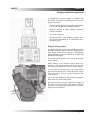
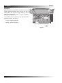
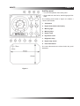
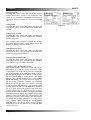
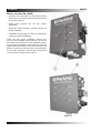
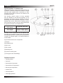
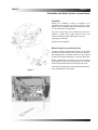
A 5” ‘B’ section pulley with two grooves (figure 3).
In this case the maximum power which can be taken
will be limited by the belts, and it will be necessary to
calculate for marginal applications.
Figure 2
Caution: Additional inertia must not be added to the
P.T.O. shaft without specialist advice. Consult your
distributor if you need advice about non-standard
drive arrangements.
Figure 3
Page 59