1
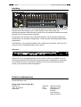
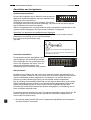
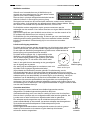
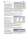
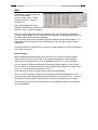
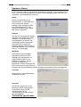
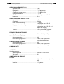
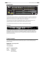
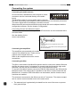
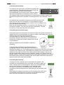
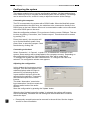
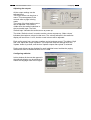
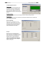
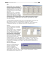
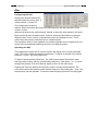
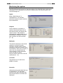
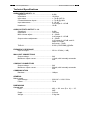
MusiCall
Installatie handleiding
Installation manual
MusiCall installatie handleiding
NL
Veiligheidsinstructies
Veiligheidsinstructies
1
Alle veiligheidsinstructies, waarschuwingen en gebruiksaanwijzingen moeten als
eerste gelezen worden.
2
Alle op het apparaat aanwezige waarschuwingen dienen opgevolgd te worden.
3
De gebruiksaanwijzing dient opgevolgd te worden.
4
Bewaar de gebruiksaanwijzing voor toekomstig gebruik.
5
Het apparaat mag nooit in de onmiddellijke nabijheid van water worden gebruikt;
voorkom de mogelijkheid van binnentreden van water en vocht.
6
Het apparaat mag alleen geplaatst of gemonteerd worden op de door de fabrikant
aanbevolen wijze.
7
Het apparaat moet zo geplaatst of gemonteerd worden, dat niets een goede
ventilatie in de weg staat.
8
Het apparaat mag nooit in de onmiddellijke nabijheid van warmtebronnen zoals
verwarmingsinstallatie delen, kachels, en andere warmte producerende apparatuur
(onder andere versterkers) worden geplaatst.
9
Sluit het apparaat alleen aan op de juiste netspanning door middel van de door de
fabrikant aanbevolen kabels, zoals beschreven in de gebruiksaanwijzing en/of
vermeld op de aansluitzijde van het apparaat.
10 Het apparaat mag alleen worden aangesloten op een wettelijk goedgekeurde
(rand)geaarde netspanningsaansluiting.
11 De netspanningskabel of het netspanningssnoer dient zo gelegd, dat er
redelijkerwijs niet overheen gelopen kan worden of geen voorwerpen op of tegenaan
geplaatst kunnen worden welke de kabel kunnen beschadigen. Speciaal moet
rekening gehouden worden met het punt waar de kabel vast zit aan het apparaat en
waar de kabel vastzit aan de netspanningsaansluiting.
12 Voorkom dat vreemde voorwerpen en vloeistoffen in het apparaat kunnen
binnendringen.
13 Het apparaat dient op de door de fabrikant aanbevolen wijze gereinigd te worden.
14 De netspanningskabel of het netspanningssnoer dient, indien voor langere tijd het
apparaat niet gebruikt wordt, uit de netspanningsaansluiting gehaald te worden.
15 In alle gevallen, wanneer er na een gebeurtenis gevaar ontstaat voor onveilige
werking van het apparaat, zoals:
x
na het beschadigd raken van de netspanningskabel of het netspanningssnoer
x
na het binnendringen in het apparaat van vreemde voorwerpen of vloeistoffen
(onder andere water)
x
na een val van het apparaat of een beschadiging van de behuizing
x
na het opmerken van een verandering in de werking van het apparaat
moet het gecontroleerd worden door daarvoor bevoegd technisch personeel.
16 De gebruiker moet geen werkzaamheden aan het apparaat uitvoeren anders dan die
in de gebruiksaanwijzing staan omschreven.
2
3
Inleiding
MusiCall installatie handleiding
Inleiding
MusiCall centrale
Het MusiCall paging systeem is een geluidsdistributie systeem dat acht verschillende
audiobronnen kan verdelen over 16 afzonderlijke zones. Met behulp van
bedieningseenheden (WallUnits) kan van elke zone op afstand de audiobron worden
gekozen en het volume worden ingesteld.
De centrale vormt het hart van het MusiCall systeem. Op de centrale worden alle
audiobronnen en versterkers aangesloten. Tevens worden de bedieningseenheden
aangesloten.
De WallUnits en de consoles betrekken hun voeding uit de centrale. Het is dus niet
nodig om extra voedingsapparaten aan te sluiten.
Qfm tuner
-
+
Fr eq Pset
4
5
QfmStereoFMTuner
6
3
7
2
Monit or
8
1
9
0
10
Power
Als de Qfm tuner wordt aangesloten op het systeem is het ook mogelijk om op de
bedieningseenheden RDS informatie van de beluisterde radiostations te ontvangen,
en eventueel de tuners op afstand te bedienen. Er kunnen maximaal twee Qfm
tuners op het systeem worden aangesloten.
Product ondersteuning
Voor vragen over het Musicall systeem, accessoires en andere produkten kunt u
contact opnemen met:
Dateq Audio Technologies B.V.
De Paal 37
1351 JG Almere
Nederland
Telefoon: (036) 54 72 222
Fax:
(036) 53 17 776
E-mail:
[email protected]
Internet:
www.dateq.nl
www.musicall.nl
NL
NL
MusiCall installatie handleiding
Aansluiten
Aansluiten van het systeem
Audiobronnen aansluiten
Op de audio-ingangen van de MusiCall centrale kunnen
apparaten worden aangesloten met een standaard line
uitgang op cinch-connectoren.
De MusiCall centrale is een mono-systeem. Wel zijn bij
de ingangen twee cinch-connectoren aanwezig. De centrale zal het stereo-signaal
direct omzetten naar een mono-signaal.
Indien het uitgangsniveau van twee audio-bronnen verschillend is kan dit later in het
systeem worden aangepast. Zie hiervoor het hoofdstuk ‘Configuratie’.
Aansluiten van apparaten met gebalanceerde uitgangen
Apparaten met een gebalanceerde uitgang op XLR-connectoren kunnen worden
aangesloten met behulp van een verloop-snoertje.
Een verloop-snoertje wordt als volgt
gemaakt:
XLR-Female
Cinch
1
2
3
Versterkers aansluiten
x
Verbind pin 2 van de XLR naar de signaalpen van de
cinch
x
Sluit pin 1 en 3 van de XLR kort en verbind deze naar
de massa van de cinch
De versterkers worden aangesloten op de
audio-uitgangen van de MusiCall centrale.
Deze uitgangen zijn ook op standaard lineniveau. De uitgangen zijn mono. Voor de
exacte aansluitgegevens kunt u de
handleiding van de versterker erop naslaan.
Qfm aansluiten
De Qfm kan met behulp van vier cinch-cinch snoertjes worden aangesloten op de
MusiCall centrale. Omdat de Qfm een stereo tuner is moeten zowel het linker als het
rechter audiokanaal worden aangesloten. De uitgangen van de Qfm kunnen in
principe op iedere willekeurige ingang van de centrale worden aangesloten.
Om de volledige functionaliteit van de Qfm tot zijn recht te laten komen moet ook de
RS232 verbinding tussen de Qfm en de centrale worden aangebracht. Deze draad
maakt communicatie tussen de tuners en de centrale mogelijk zodat de RDS
informatie op het MusiCall netwerk kan worden weergegeven, en bediening van de
tuner op afstand mogelijk wordt.
De antenne wordt met behulp van een F-connector aangesloten op de Qfm tuner. De
antenne uitgang kan eventueel worden gebruikt om het antenne signaal door te
lussen naar een andere tuner.
!
x De antenne ingang van de Qfm tuner is galvanisch gescheiden van het systeem
om aard-lussen te voorkomen.
4
5
Aansluiten
MusiCall installatie handleiding
NL
WallUnits aansluiten
Gebruik voor het aansluiten van de WallUnits op de
centrale een twee-aderig snoer. De twee aders worden
gebruikt voor zowel voeding als data.
Hiervoor kan in principe onafgeschermde kabel worden
gebruikt. Indien er in de omgeving een erg hoog
storingsniveau heerst kan de communicatie tussen de centrale en de WallUnits
verstoord raken. In dit geval kan een afgeschermde kabel uitkomst bieden. Storing
kan worden veroorzaakt door bijvoorbeeld dimmers, motoren etc.
De WallUnits worden aangesloten op de groene connectoren aan de
achterzijde van de centrale. Voor iedere zone kan een eigen WallUnit worden
aangesloten.
Het is ook mogelijk om geen WallUnit aan te sluiten, en met het console of de
PC-software de audiobron en het volume in te stellen.
De WallUnits zijn niet polariteitsgevoelig. Er kunnen per zone maximaal twee
wallunits parallel worden geschakeld. Deze twee wallunits hebben dezelfde
logische functionaliteit. Dit kan handig zijn in een ruimte met meerdere
ingangen.
Naar de
WallUnit
Lokale audio ingang aansluiten
De lokale audio ingangen worden aangesloten op de buitenste twee pennen van de
groene connectoren. Als een lokale audio ingang wordt aangesloten moet
er ook altijd een WallUnit zijn aangesloten op deze zone, omdat anders de
lokale ingang nooit geselecteerd kan worden!
De lokale audio ingangen zijn, in tegenstelling tot de
WallUnits, wel polariteitsgevoelig. Verkeerd aansluiten
- +
van de lokale ingang heeft tot gevolg dat er geen audio
wordt doorgegeven. Er zal echter niets defect raken.
Intern is een gain-trimmer aanwezig om de gevoeligheid
van de ingang aan te passen.
+
Naar de
lokale ingang
Achteraanzicht
Om storing op het audiosignaal te voorkomen moet voor
lokale audio input
de lokale audio ingangen afgeschermde kabel
(bijvoorbeeld microfoonkabel) worden gebruikt. De afscherming van de
microfoonkabel kan aan de centrale worden bevestigd aan de min-pool van het
connectorblokje. Eventueel kan de afscherming bij de MRA worden bevestigd aan de
middelste pen op het aansluitblokje (zie aarde-figuur op de tekening). Let bij het
installeren van de bekabeling er op dat de microfoonkabel niet over langere
afstanden vlak naast de speakerkabels wordt getrokken om rondkoppelingen te
voorkomen. Het is niet aan te raden de bekabeling van de audio ingang samen met
de bekabeling van de WallUnits in één afgeschermde kabel te leggen, omdat de data
over de audio hoorbaar kan zijn.
Consoles aansluiten
Op het systeem kunnen maximaal twee bedieningsconsoles worden
aangesloten. De bedieningsconsoles gebruiken altijd een
vierdraadsverbinding; twee voor data en voeding en twee voor de microfoon.
Hiervoor kan in principe ook een onafgeschermde kabel worden gebruikt, het
is echter aan te raden ook hiervoor afgeschermde kabel te gebruiken.
Eén aderpaar wordt aangesloten op de middelste twee pennen van het
groene aansluitblokje op de centrale, het andere aderpaar wordt aangesloten
op de buitenste twee aansluitpennen. Beide aderparen zijn niet
polariteitsgevoelig.
Als de bijgeleverde aansluitdoos wordt gebruikt moeten de rode en groene
draad op de binnenste en de zwarte en gele draad op de buitenste
schroeven worden aangesloten.
Naar het
console
NL
MusiCall installatie handleiding
Aansluiten
Telefoonlijn aansluiten
Het is mogelijk om oproepen per telefoon door te geven.
Zodra de centrale wordt gebeld zal deze de lijn opnemen, en een
oproep naar de speciaal daarvoor gereserveerde groep
doorgeven. Wanneer de verbinding wordt verbroken zal de ingesprekstoon door de centrale worden herkend, en de verbinding wordt automatisch
verbroken.
Sluit de A, en B van de telefoonlijn aan op de ‘line’ aansluiting van de centrale.
Remotes
Console 1
Console 2
Line
Logic
Hybrid
Made by:
R-Bal C-Bal
Almere, The Ne
Veel gestelde vragen
x Na het aansluiten van de WallUnit verschijnt de text ‘Musicall Please wait…’,
en na enige tijd ‘No data from host…’ in beeld?
Æ Controleer met behulp van een multimeter de spanning op de
aansluitklemmen van de WallUnit met de Wallunit aangesloten.
Normaal gesproken zal dit 24Vdc zijn. Bij een erg lange kabel zal de
spanning iets zakken, omdat er spanningsverlies over de kabel optreed. De
WallUnit zal blijven werken tot ongeveer 13Vdc.
Als de spanning onbelast (dus zonder WallUnit) slechts 15Vdc is, dan is het
zeer waarschijnlijk dat de kabel is aangesloten op de buitenste twee
aansluitklemmen tbv. de lokale audio ingang!
x Als de lokale audio ingang is geselecteerd, en het volume wordt aangepast is
een hoog knisperend geluid hoorbaar?
Æ Als de kabel van de WallUnit en de Audio input langs elkaar liggen kan de
data storen op de audio. Gebruik bij voorkeur afgeschermde kabel voor de
audio input.
6
7
Configureren
MusiCall installatie handleiding
Configureren van het systeem
In dit hoofdstuk worden de systeeminstellingen behandeld. Deze instellingen moeten
in principe slechts eenmalig worden gemaakt om het MusiCall systeem in het
gebouw te integreren. De gemaakte instellingen kunnen worden bewaard in een
bestand, zodat het mogelijk is met om de instellingen aan te passen en eventueel
weer te herstellen.
Aansluiten van de computer
De computer wordt met een RS232-kabel aangesloten op het systeem. Indien alleen
een MusiCall centrale wordt gebruikt, dus zonder de Qfm tuner, kan de computer
direct op de centrale worden aangesloten.
Als ook een Qfm tuner is aangesloten kan de PC op de vrije RS232 poort van de
tuner worden aangesloten.
Start nu de configuratiesoftware op. Eerst moet de juiste COM-poort op de computer
worden aangegeven. Druk hiervoor op ‘Connection’ en dan op ‘Select comport’. Dit
scherm kan ook worden aangeroepen door op F12 te drukken.
Druk op ‘Auto search’, en de computer
zal nu zelf de MusiCall centrale
proberen te vinden. Druk nu op ‘Save’
om de gevonden comport te bewaren,
en sluit het scherm door op ‘OK’ te
drukken.
Verbinding met de centrale maken
Druk op ‘Connection’ Æ ‘Connect’, of druk op F10, om de verbinding met het
systeem actief te maken. De instellingen worden gedownload in het geheugen.
Afhankelijk van de configuratie zullen de menu’s ‘MusiCall Host’ en ‘Qfm’ al dan niet
actief worden.
Om het systeem te configureren moet het menu ‘MusiCall host’ Æ ‘Configure host’
worden geselecteerd. Het configuratiescherm wordt nu zichtbaar.
Ingangsinstellingen aanpassen
In dit scherm kan de naam van iedere
ingang worden aangepast.
De naam die hier wordt ingevuld is tevens
de naam die in het display van de
WallUnits verschijnt als de ingang
geselecteerd is. Door het vakje ‘inputs
enabled’ uit te vinken zal de ingang niet
meer te selecteren zijn door de WallUnits.
Tijdelijk ongebruikte ingangen kunnen zo
automatisch worden overgeslagen.
Met de ‘Attenuation’ schuifbalk kan de ingangsverzwakker worden aangepast.
Hiermee kunnen niveauverschillen tussen de verschillende audio-bronnen wordt
weggewerkt.
Als de gegevens zijn ingevuld kunnen ze worden bewaard in de centrale door op
‘Update’ te drukken.
NL
NL
MusiCall installatie handleiding
Configureren
Als het vakje ‘Update inputs after update’ actief is worden de gemaakte instellingen
direct door de centrale overgenomen. Door dit vakje uit te schakelen worden de
nieuwe instellingen pas overgenomen als een WallUnit de ingang selecteerd.
!
x Ingangen die permanent ongebruikt blijven kunnen in de scrollijsten worden
verwijderd. Zie hiervoor het hoofdstuk ‘scrolls’.
Uitgangen aanpassen
Hier kunnen alle instellingen worden
gemaakt die betrekking hebben op
de uitgangszones. De verschillende
zones kunnen een naam krijgen.
Deze naam verschijnt in het console
op het moment dat een oproep
wordt geplaatst.
De naam voor de lokale bron wordt
in het scherm van de WallUnits
getoond zodra de lokale bron actief
wordt. Het selectieveld ‘Default input’ geeft de ingang aan die actief wordt gemaakt
als de centrale wordt aangezet.
De schuifbalk ‘Default volume’ wordt gebruikt om geluidsniveau bij het inschakelen
van het systeem in te stellen.
De schuifbalk ‘Main volume’ geeft de maximale geluidssterkte in een ruimte weer. De
volumeindicatie op het scherm van de WallUnits blijft altijd van 1 tot 30 lopen; het
geluid zal echter zachter klinken als de schuifbalk lager wordt ingesteld.
Iedere uitgang heeft een tweebands-equaliser en een loudness instelling. Met
schuifbalken ‘High’ en ‘Low’ kan de equaliser worden ingesteld. De uitgang zal de
instelling overnemen zodra op de ‘Update’ knop wordt gedrukt, en het vakje ‘Update
outputs after upload’ is ingeschakeld.
Per zone kan worden aangegeven of de zone al dan niet mag worden toegesproken,
en of er voor de oproep een bel-signaal hoorbaar moet zijn. Tevens kan het volume
van een oproep 6, of 12dB harder worden weergegeven dan de normale bronkeuze.
WallUnits configureren
In dit scherm kunnen de verschillende
teksten worden aangepast die op het
schermpje van de WallUnits
verschijnen.
Hierdoor kan het systeem worden
aangepast aan de taal van de
gebruikers.
8
9
Configureren
MusiCall installatie handleiding
Consoles configureren
Normal texts
Net zoals bij de WallUnits kunnen bij de
consoles de teksten worden aangepast.
Klik op de selectie-veld om een van de
teksten weer te geven, en eventueel aan
te passen. Als de tekst ‘Fixed field’
verschijnt is dit veld gereserveerd door
het systeem.
Backlight settings
Met deze schuifbalk kan de tijd worden ingesteld dat het backlight van het tableau
aanblijft zodra een toets is ingedrukt.
Programming
Met deze twee selectievakjes kan worden aangegeven welke consoles de centrale
mogen configureren. Door het vakje uit te schakelen kan het programmeermenu niet
worden benaderd.
Room combining
Hier worden de master-slave
koppelingen weergegeven. Klik met de
muisaanwijzer op de naam van de
masterzone, en de slave-zones worden
direct weergegeven. Het is nu mogelijk
om slaves toe te voegen, of te
verwijderen.
Groups
Hier worden de groepen ingesteld. Elke
zoneknop op het tableau (1…16) is kan
één of meerdere zones toespreken.
Standaard staat onder knop 1 alleen
zone 1; onder knop 2 alleen zone 2 etc.
Elke groep kan een eigen naam krijgen.
Deze naam verschijnt in het display van
de MPC-16 als de groep wordt
toegesproken.
NL
NL
MusiCall installatie handleiding
Configureren
Qfm
Als een Qfm-tuner is aangesloten kan
in dit scherm worden aangegeven op
welke ingangen de tuners zich
bevinden. Dit is nodig om de RDSinformatie naar de juiste WallUnits te
sturen, en om de bediening van de
tuner mogelijk te maken.
Als in het selectieveld de tekst ‘RDS’ is
gekozen wordt de ontvangen RDS
informatie weer gegeven op de displays
van de WallUnits. Als geen RDS beschikbaar is wordt de stattionsnaam uit het
geheugen van de tuner weergegeven. Als ook die niet is geprogrammeerd zal het
preset nummer worden weergegeven. Indien de RDS weergave niet gewenst is moet
‘MusiCall name’, of ‘Station name’ worden geselecteerd. In het eerste geval wordt
alleen de ingangsnaam weergegeven; in het tweede geval wordt de stationsnaam uit
het tunergeheugen gelezen.
Om een tuner te reserveren voor een van de zones moet het vakje ‘Assign tuner’
worden aangevinkt (zoals bij tuner 3 in dit voorbeeld). De tuner kan nu niet meer
worden geselecteerd door de andere zones.
Als een tuner in een van de scrollijsten is opgenomen is het vakje ‘assign tuner’ niet
selecteerbaar. Om de status te kunnen wisselen moet de tuner eerst uit alle
scrollijsten worden verwijderd.
Scrolls
In dit scherm staan de scrollijsten per
zone weergegeven.
Iedere zone kan dus een eigen lijst
met ingangsbronnen beschikbaar
hebben.
In dit voorbeeld is een tuner
toegekend aan deze zone. Als
ingangsbron kan dan ook gekozen
worden uit de 30 presets van de
toegekende tuner. Als geen tuner is
toegekend zal het rechter scherm niet zichtbaar zijn.
Om items toe te voegen kan de bron naar de scrollijst worden gesleept. Het is ook
mogelijk om te dubbelklikken op de bron. Bronnen verwijderen kan door te
dubbelklikken, of door de bron terug te slepen naar de lijst met beschikbare zones.
Het is ook mogelijk de eigen lokale bron in de scrollijst toe te voegen.
Ook de andere uitgangen kunnen worden opgenomen, zolang deze maar in
hetzelfde bereik liggen (1..8 en 9…16).
Het is niet mogelijk om een uitgang in de scrollijst op te nemen die al een andere
uitgang in de eigen scrollijst heeft staan. In bovenstaand voorbeeld kan ‘Output 1’
dus niet meer worden opgenomen in de scrollijsten van andere uitgangen.
Configuratie bewaren
Als alle instellingen zijn gemaakt kan
de volledige configuratie in een enkel
bestand worden opgeslagen.
Druk in het hoofdscherm op ‘File’Æ
‘MusiCall host’ Æ ‘Download to file’.
Nu verschijnt een venster waar de naam van het bestand, en de locatie kunnen
worden ingevoerd. Om de configuratie terug op te slaan in de centrale moet de optie
‘Upload from file’ worden gekozen.
10
11
Configureren
MusiCall installatie handleiding
Qfm
Het instellen van de presets met
de PC software kan
door het menu ‘Qfm’Æ ‘Show
presets’ te kiezen, of met de
sneltoets F8.
Het configuratiescherm wordt
geopend. Selecteer de preset en typ de nieuwe frequentie in op het toetsenbord.
Druk op <enter> om te bevestigen.
Hier kan ook de stationsnaam in het geheugen van de tuner worden opgeslagen.
Tevens is het mogelijk de tuner naar mono te schakelen. Dit kan handig zijn om ruis
te onderdrukken bij een slechte ontvangst.
Door het vakje ‘Keys on front enabled’ kan de bediening van de Qfm worden in,- of
uitgeschakeld. Dit voorkomt dat de instellingen van de tuner per ongeluk worden
aangepast.
Als alle presets zijn ingesteld kan op ‘Upload’ worden gedrukt om de nieuwe presets
op te slaan in de tuner.
Qfm bediening
Met de hoofdtelefoonaansluiting op het front kan een van de vier tuners worden
afgeluisterd. De actieve tuner staat in het display weergegeven. Omschakelen
tussen de tuners gebeurd door in het hoofdscherm op de + of - toets te drukken.
Om een preset te selecteren moet de Pset toets worden ingedrukt. In het scherm
komt de tuner, en de gekozen preset met de bijbehorende frequentie te staan. Druk
nu op + of - om door de presets heen te lopen.
Druk nogmaal op Pset om terug te keren naar het hoofdscherm.
Door nu op de Freq-toets te drukken kan de frequentie worden aangepast. In het
scherm verschijnt het presetnummer en de frequentie. Druk op de + of de - toets om
de frequentie aan te passen. Druk op Freq om de nieuwe frequentie op te slaan.
Als de toetsen op het front niet werken dan is het mogelijk dat deze in de software
zijn uitgeschakeld!
NL
NL
MusiCall gebruikers handleiding
Uitlezen
Systeem uitlezen
De PC software maakt het mogelijk om de huidige instellingen van het systeem uit te
lezen. Het is dus ook mogelijk om te bekijken welke ingangen worden beluisterd, de
ingestelde volumestanden per zone etc.
Inputs
Druk in het hoofdscherm op
‘MusiCall host’ Æ ‘Extended info’.
In dit scherm kan worden
bekeken welke ingangen al dan
niet selecteerbaar zijn, en de
ingangsverzwakking per ingang
kan worden uitgelezen.
Outputs
Hier kan per uitgangszone worden
afgelezen naar welke bron wordt
geluisterd, en wat de huidige
volumestand is. Dit scherm zal
automatisch worden aangepast
zodra een van de zones de
instelling aanpast. Deze functie is
alleen beschikbaar voor de laatste
acht (9…16) uitgangen!
WallUnits
In dit scherm wordt zichtbaar
gemaakt op welke zones de
WallUnits zijn aangesloten, en
welke firmware versie in de
WallUnits is geladen. Tevens
kunnen de master-slave
koppelingen worden weergegeven.
Door een master of slave zone aan
te wijzen met de muisaanwijzer worden de andere gekoppelde zones weergegeven.
Consoles
Deze functie is niet beschikbaar in
de MPM16 centrale.
Host info
Hier worden gegevens over de
MusiCall centrale weergegeven.
De firmware versie van de
hoofdprocessor en de
communicatie processor worden
hier weergegeven.
Technische specificaties
12
13
Technische specificaties
MusiCall installatie handleiding
NL
AUDIO INGANGEN INPUT 1...8
Signaalniveau .................................................. 0 dBu
Impedantie ....................................................... 10 kOhm
Ingangsruis ...................................................... < -78 dB (IHF-A)
Overspraak tussen inputs ................................ < -72 dB @ 1kHz
Ingangsverzwakking ........................................ 0...25 dB
in 20 stapjes van 1.25 dB
Headroom ........................................................ 10 dB
AUDIO UITGANGEN OUTPUT 1...16
Signaalniveau .................................................. 0 dBu
Impedantie ....................................................... 150 Ohm
Hoofd volume instelling.................................... 0...-50 dB
in 40 stapjes van 1.25 dB
Uitgangs volume instelling ............................... 0...-50 dB
in 20 stapjes van 1.25 dB; en 10
stapjes van 2.50dB
daarna mute: -75 dB
THD+N............................................................. 0.08% (CCIR-RMS) @ 0dBu
FREQUENTIEKARAKTERISTIEK
Ingang naar uitgang......................................... 25 Hz...25 kHz (-1 dB)
WALLUNIT AANSLUITINGEN
Uitgangsspanning ............................................ 24V
Maximale uitgangsstroom ................................ 110mA, met ingebouwde
automatische zekering
CONSOLE AANSLUITINGEN
Uitgangsspanning ............................................ 24V
Maximale uitgangsstroom ................................ 500mA, met ingebouwde
automatische zekering
COMMUNICATIE
Baudrate .......................................................... 14kbps
ALGEMEEN
Voedingsspanning
Spanningsbereik .............................................. 230 VAC +/-10%/ 50 Hz
Vermogen ........................................................ 70 W
AFMETINGEN EN GEWICHT
Centrale
Front ................................................................ 483 x 132 mm (B x H) = 19”,
3HE
Kastdiepte........................................................ 215 mm
Gewicht............................................................ 5.3 kg Netto
MusiCall Installation manual
EN
Safety instructions
Safety instructions
1
All safety instructions, warnings and operating instructions must be read first.
2
All warnings on the equipment must be heeded.
3
The operating instructions must be followed.
4
Keep the operating instructions for future reference.
5
The equipment may never be used in the immediate vicinity of water; make sure that
water and damp cannot get into the equipment.
6
The equipment may only be installed or fitted in accordance with the manufacturers
recommendations.
7
The equipment must be installed or fitted such that good ventilation is not obstructed
in any way.
8
The equipment may never be installed in the immediate vicinity of sources of heat,
such as parts of heating units, boilers, and other equipment which generates heat
(including amplifiers).
9
Connect the equipment to a power supply of the correct voltage, using only the
cables recommended by the manufacturer, as specified in the operating instructions
and/or shown on the connection side of the equipment.
10
The equipment may only be connected to a legally approved earthened mains power
supply.
11
The power cable or power cord must be positioned such that it cannot be walked on
in normal use, and objects which might damage the cable or cord cannot be placed
on it or against it. Special attention must be paid to the point at which the cable is
attached to the equipment and where the cable is connected to the power supply.
12
Ensure that foreign objects and liquids cannot get into the equipment.
13
The equipment must be cleaned using the method recommended by the
manufacturer.
14
If the equipment is not being used for a prolonged period, the power cable or power
cord should be disconnected from the power supply.
15
In all cases where there is a risk, following an incident, that the equipment could be
unsafe, such as:
x
if the power cable or power cord has been damaged
x
if foreign objects or liquids (including water) have entered the equipment
x
if the equipment has suffered a fall or the casing has been damaged
x
if a change in the performance of the equipment is noticed
it must be checked by appropriately qualified technical staff.
16 The user may not carry out any work on the equipment other than that specified in the
operating instructions.
2
3
Introduction
MusiCall Installation manual
Introduction
MusiCall central
The MusiCall paging system is a music-distribution system, capable of distributing
eight audio-sources over 16 independent zones. With the remote-controllers, the
wallunits, the audio-source and the volume can be adjusted.
The central unit is the heart of the MusiCall system. All the audio-sources, the
amplifiers and the remote-controllers will be connected to this unit.
The Wallunits and consoles do not need an external power-supply.
Qfm tuner
-
+
Fr eq Pset
4
5
QfmStereoFMTuner
6
3
7
2
Monit or
8
1
9
0
10
Power
With the Qfm tuner connected to the system it is possible to distribute the RDS
information of all four tuners over the MusiCall system. Another nice feature is the
possibility to remotely control the tuner. Two Qfm tuners can be connected to the
system simultaneously.
Product support
If you have any questions about the MusiCall system, or other DATEQ products
please contact:
Dateq Audio Technologies B.V.
De Paal 37
1351 JG Almere
The Netherlands
Telephone: +31 36 54 72 222
Fax:
+31 36 53 17 776
E-mail:
[email protected]
Internet: www.dateq.nl
www.musicall.nl
EN
EN
MusiCall Installation manual
Connecting
Connecting the system
Connecting the audio-sources
All sources with a standard line-level outputs on cinchconnectors can be connected directly to the audioinputs.
The MusiCall central is a mono-switch matrix, however
two cinch connectors are available so that a stereo source can be easily connected.
The stereo signal will be immediately converted to mono.
When two audio-sources have different output levels this can be adjusted with the
configuration software. See the chapter ‘Configuration’.
Connecting devices with balanced outputs
Audio-devices with a balanced output on a XLR-connector can be connected with a
converter-cable.
See the drawing for the
correct connections:
XLR-Female
1
Cinch
2
3
x
Connect XLR pin 2 to the signal pin of the cinch
connector
x
Short XLR pin 1 and 3 and connect to the ground pin of
the cinch connector
Connecting the amplifiers
The amplifiers are connected to the audiooutputs of the MusiCall unit. These (mono)
outputs are at normal line-level.
Refer to the amplifiers manual for correct
connections.
Connecting the Qfm
The Qfm is connected to the MusiCall system with four cinch-cinch cables. Because
the Qfm is a stereo tuner it is important to connect both the left and the right audio
channels! The Qfm can be connected to any of the eight audio inputs.
To use all of the Qfm’s features connect the RS232 cable between the Qfm and the
MusiCall central. This cable makes it possible for the Qfm to communicate with the
MusiCall unit, so that the RDS information can be showed, and the remote-control
functions are enabled.
The antenna is connected to the Qfm tuner with a F-connector. The antenna output
can be used to connect another tuner to the same aerial.
!
x The antenna input is galvanically insulated from the rest of the tuner to prevent
from ground-loops.
4
5
Connecting
MusiCall Installation manual
EN
Connecting the wallunits
The wallunits are connected to the MusiCall system with
a two-wire cable. These two wires are used for both the
power-supply and the data communication.
Unshielded cable can be used for this. However when a
high level of interference is expected it is more safe to
use shielded cables, because otherwise the communication between the host and
the wallunit might become unreliable. Interfering sources can be dimmers, motors
etc.
The wallunits are connected to the green connectors at central unit.
Each zone can have it’s own wallunit. It’s also possible to set the
audio-source and the volume with the console or the PC software, and
leave the wallunit unconnected.
Wallunits are not polarity sensitive. A maximum of two wallunits can be
connected in parallel. They will have the same functionality. This can
be useful in a room with more than one entrance.
To the
WallUnit
Connecting the local audio input
Local audio inputs are connected to the outermost pins of the green connectors. A
wallunit has to be connected when you want to connect a local audio input, because
otherwise the local input cannot be selected.
The local inputs are, unlike the wallunits, sensitive to
the polarity. When the local input is connected in the
wrong way no audio will be heard, however the unit will
not get defective.
- +
Internally a gain-trimmer is available to adjust the
sensitivity.
+
To the local
input
Rearview of
To prevent from interference use shielded cable (i.e.
local input
microphone-cable) to connect the local audio inputs to
the MusiCall central unit. The shielding must be connected to the minus of the green
connector at the MusiCall host. At the MRA the shielding can be connected to the
middle pin of the XLR-connector (See earth-symbol in the drawing). Keep in mind
that the shielded MRA-cable must not be placed in parallel (very closely) with the
speaker cable for a long distance because this could cause oscillations. Do not draw
the wallunit-cable in the same shielded cable as the MRA, because the data will be
heard over the audio signal from the MRA.
Connecting the consoles
A maximum of two consoles can be connected to the system. The
consoles are connected with a four-wire cable; two wires for data and
power, and two wires for the microphone signal. An unshielded cable
can be used, however it is advisable to use a shielded cable.
One pair is connected to the middle two pins, the other pair is
connected to the outermost two pins. Both pairs are not sensitive to the
polarity.
When using the equipped connector-box the red and green cable must
be connected to the inner two connectors, and the black and yellow
cable must be connected to the outer-two connectors.
To the
console
EN
MusiCall Installation manual
Connecting a subscriber line
It is possible to make a page by means of a telephone.
When the Musicall host is called the system will pick-up the line, and
send the message to the specially reserved group.
The system will detect the busy-tones and disconnect automatically.
Connecting
6
Remotes
Console 1
Console 2
Line
Logic
Connect the subscriber line to the ‘line’ connection on the system.
Frequently asked questions
x After connecting the Wallunit the text ‘Musicall Please wait…’, and after some
time ‘No data from host…’ appears?
Æ Check the voltage on the wallunits connector with the wallunit connected.
In a normal situation this should be approximately 24Vdc. On a very long
cable length this could be slightly lower because of the voltage drop over the
cable. The wallunits will work up to 13Vdc.
When the voltage without the wallunit is 15Vdc, it is very likely that the cable
is connected to the outermost pins at the matrix side. These two pins are to
be used by the MRA instead!
x When I select the local input, and adjust the volume I can hear a high-pitch
buzzing sound?
Æ When the MRA and wallunit cable are in parallel they will interfere with
each other. It is recommended to use a shielded cable for the MRA and a
separate cable for the wallunit.
Hybrid
Made by:
R-Bal C-Bal
Almere, The Ne
7
Configuring
MusiCall Installation manual
Configuring the system
This chapter explains how to use the configuration software. All these settings have
to be made only once to integrate the MusiCall system into the building. The settings
can be stored into a file, so that it is easy to adjust and restore all the settings.
Connecting the computer
The PC is connected to the system with a RS232 cable. When the MusiCall system
is connected without the Qfm tuner, the cable has to be connected to directly to the
RS232 port on the host. When a Qfm tuner is connected the cable can be connected
to the free RS232 port on the tuner.
Start the configuration software. First you have to find the correct COM-port. This can
be done by clicking ‘Connection’, then ‘Select comport’. This window can be access
by pushing F12.
Press ‘Auto search’, the computer will
try to find the MusiCall system. Now
press ‘Save’ to store the comport. Close
the window by clicking ‘OK’.
Connecting to the host
Select ‘Connection’ Æ ‘Connect’, or push F10, to establish the connection to the
system. Some settings will be downloaded to the computers memory. Depending on
the configuration the menu’s ‘MusiCall Host’ and ‘Qfm’ will be made active.
To configure the system the menu ‘MusiCall host’ Æ ‘Configure host’ has to be
selected. The configuration window now appears.
Adjusting the configuration
In this window the input names can be
changed. This name will appear in the
wallunits displays when the input is
selected. By un-selecting the box
‘inputs enabled’ the input will not be
selected by the wallunits. Temporarily
disconnected inputs can be made
inactive.
The slider ‘Attenuation’ controls the
input attenuation. Use this to match the
different audio-levels of the audiosources.
Store the configuration by pressing the ‘Update’ button.
When the box ‘Update inputs after update’ is selected, the settings will become
active immediately, otherwise the new settings will be activated when a wallunit
selects the input.
!
x Permanently unused inputs can be removed in the scroll-lists. See the chapter
‘scrolls’ for more information.
EN
EN
MusiCall Installation manual
Configuring
Adjusting the outputs
All the output settings can be
adjusted here.
The output zones can be given a
name. This can appears in the
console when a page is being
made.
The name of the local audio-source
can be adjusted. This name is
visible when the wallunit switches to
the local audio input. The field
‘Default input’ indicates the audio-source at power-up.
The slider ‘Default volume’ is used to set the volume at power-up, ‘Main volume’
indicates the maximum volume in that zone. The volume-indicator in the wallunits
display will scroll from 1 to 30, but the overall volume will be adjusted.
Each audio-output has a two-way equaliser and a loudness control. The sliders ‘High’
and ‘Low’ adjust the output equaliser. The output will latch the settings when the
‘Update’ button is pushed, and the box ‘Update outputs after upload’ is selected.
Paging and chimes can be disabled for each individual zone; besides the paging
volume can have an additional boost of 6 or 12dB.
Configuring wallunits
In this window all the text that appear in
the wallunits display can be adjusted to
match the language used in the region.
8
9
Configuring
MusiCall Installation manual
Configuring the consoles
Normal texts
All the texts in the console display can
be adjusted. Click the selection box to
select one of the texts, and adjust the
text if necessary. When the text ‘Fixed
field’ appears this field is reserved by the
system.
Backlight settings
Use this slider to adjust the time the display remains lit after pushing a button.
Programming
Enable the selection box if the console may configure the MusiCall host. Uncheck the
box to disable this function.
Room combining
Master-slave combinations can be
made here. When clicking on a masterzone all the slave-zones will light up. It
is possible to add or remove masterslave combinations in this way.
Groups
Group-keys can be assigned here.
Each zone-key (1..16) stands for one or
more output-zones. By default key 1 is
linked to zone 1, key 2 is linked to
output 2 etc. A name can be given to
each group individually. This name will
appear in the MPC-16 when a page is
made to that group.
EN
EN
MusiCall Installation manual
Configuring
Qfm
When the Qfm tuner is connected the
MusiCall host must be told to which
inputs the tuners are connected. This is
necessary to display the corresponding
RDS information on the wallunits, and
to enable the remote-control functions
of the tuner.
When the text ‘RDS’ is selected the
RDS information of the tuner will be
displayed when this input is selected.
When no RDS information is available
the station name will be showed. When no station name is programmed the preset
number will be showed. When you don’t want to show the RDS information select the
text ‘MusiCall name’, or ‘Station name’. Now the regular input-name, or the station
name will be showed.
To reserve a tuner for a specific output zone select the box ‘Assign tuner’ (tuner 2 in
this example). The tuner can not be selected by any of the other zones.
When a tuner is in one of the scroll-lists the box ‘assign tuner’ can not be selected.
To change the status, the tuner has to be removed from all the scrolls first!
Scrolls
This window shows the scroll-list for
each zone. Each zone can have its
own list of inputs.
In this example a tuner is assigned to
this output. All 30 presets of the Qfm
can be selected as input for the
scroll-list. When no tuner is assigned
to the output zone the right window
will not be visible. To add inputs to
the scroll-list simply drag-and-drop
the inputs to the scroll-list. To remove
them drop the input back in the
available zones list. You can also add your own local input, or other outputs to the
scroll, as long as the other outputs have the same range (ie. 1…8 or 9…16). It is not
possible to add an output to the scroll-list which already includes another output in
it’s scroll-list. In the example above ‘Output 1’ can’t be inserted into the scroll-list of
the other outputs.
Store the configuration
When all the settings have been
made the configuration can be
stored on the computer.
Click ‘File’ Æ ‘MusiCall host’ Æ
‘Download to file’. Now a window
appears where the file name and the location of the file can be entered. To restore
the configuration select ‘Upload from file’.
10
11
Configuring
MusiCall Installation manual
Qfm
Configuring the Qfm
Entering the presets with the PC
software select the menu ‘Qfm’ Æ
‘Show presets’, or press F8.
The configuration window is
opened. Select the preset and enter the new frequency with the keyboard. Press
<enter> to store.
When all the presets are entered press ‘Upload’ to store the new presets in the tuner.
Each preset can have a station name. It can be entered in the textbox on the right.
When the box ‘Tuner x mono’ is checked the output is switched to mono. This is
useful when the signal is interfered due to a bad reception.
The checkbox ‘Keys on front enabled’ can enable or disable the four switches on the
front to prevent accidental switching the tuner to a different preset.
Operating the Qfm
The headphones output can be used to monitor the signal of the currently selected
tuner. The tuner number is showed in the display. To switch to another tuner simply
press the + or the - key on the Qfm-front.
To select a preset push the PSet key. The LCD-screen shows the selected tuner,
and the preset number with the corresponding frequency. Now press +, or - to scroll
through the presets. Push the PSet key again to return to the main menu.
Pushing the Freq key adjusts the frequency of the currently selected preset. The
LCD-screen shows the preset number and the frequency. By pushing the + and - key
the frequency can be adjusted. To store the new frequency push the Freq key again.
EN
EN
MusiCall Installation manual
Monitoring
Monitoring the system
The PC software can be used to view the settings of the MusiCall host, and monitor
the system. So it is possible to monitor the output zones, the selected inputs, the
volume settings etc.
Inputs
Select ‘MusiCall host’ Æ
‘Extended info’. This window
show the (in)active inputs, and the
input attenuators.
Outputs
In this window it is possible to
monitor the selected input for all
the output zones, and monitor the
output volume. This window is
automatically updated when any of
the settings is changed. Only the
last 8 outputs can be monitored
(9…16)
Wallunits
This window shows the connected
wallunits, and their firmware
revisions. Another feature is the
possibility to show the master-slave
combinations. When the a master or
slave zone is selected with the
mouse-pointer, all the combined
zones will light up green.
Only the last 8 connections can be
monitored (9…16)
Consoles
This window is not used in the
MPM8.16 matrix.
Host info
Information about the MusiCall host
is showed here. The firmware
version of the main-controller and
the communications controller are
displayed.
12
13
Technical specifications
MusiCall Installation manual
EN
Technical Specifications
AUDIO INPUTS INPUT 1...8
Signallevel ....................................................... 0 dBu
Impedance ....................................................... 10 kOhm
Input noise ....................................................... < -78 dB (IHF-A)
Crosstalk between inputs................................. < -72 dB @ 1kHz
Input attenuators.............................................. 0...25 dB
in 20 steps of 1.25 dB
Headroom ........................................................ 10 dB
AUDIO OUTPUTS OUTPUT 1...16
Signallevel ....................................................... 0 dBu
Impedance ....................................................... 150 Ohm
Main volume adjust.......................................... 0...-50 dB
in 40 steps of 1.25 dB
Output volume adjustment ............................... 0...-50 dB
in 20 steps of 1.25 dB; and 10
steps of 2.50dB
then mute: -75 dB
THD+N............................................................. 0.08% (CCIR-RMS) @ 0dBu
FREQUENCY RESPONCE
Input to output.................................................. 25 Hz...25 kHz (-1 dB)
WALLUNIT CONNECTIONS
Output voltage ................................................. 24V
Maximum output current .................................. 110mA, with internally automatic
fuse
CONSOLE CONNECTORS
Output voltage ................................................. 24V
Maximum output current .................................. 500mA, with internally automatic
fuse
COMMUNICATION
Baudrate .......................................................... 14kbps
GENERAL
Mains supply
Input voltage .................................................... 230 VAC +/-10%/ 50 Hz
Power............................................................... 70 W
DIMENSIONS
Central unit
Front ................................................................ 483 x 132 mm (B x H) = 19”,
3HE
Depth ............................................................... 215 mm
Weight.............................................................. 5.3kg Net