1
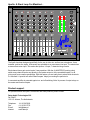
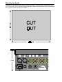
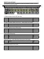
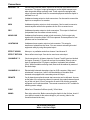
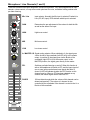
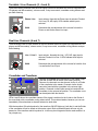
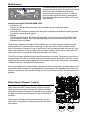
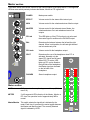
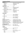
APOLLO
USER MANUAL
Safety instructions
1
All safety instructions, warnings and operating instructions must be read first.
2
All warnings on the equipment must be heeded.
3
The operating instructions must be followed.
4
Keep the operating instructions for future reference.
5
The equipment may never be used in the immediate vicinity of water; make sure that water and
damp cannot get into the equipment.
6
The equipment may only be installed or fitted in accordance with the manufacturer's
recommendations.
7
The equipment must be installed or fitted such that good ventilation is not obstructed in any
way.
8
The equipment may never be installed in the immediate vicinity of sources of heat, such as
parts of heating units, boilers, and other equipment which generates heat (including amplifiers).
9
Connect the equipment to a power supply of the correct voltage, using only the cables
recommended by the manufacturer, as specified in the operating instructions and/or shown on
the connection side of the equipment.
10
The equipment may only be connected to a legally approved earthed mains power supply.
11
The power cable or power cord must be positioned such that it cannot be walked on in normal
use, and objects which might damage the cable or cord cannot be placed on it or against it.
Special attention must be paid to the point at which the cable is attached to the equipment and
where the cable is connected to the power supply.
12
Ensure that foreign objects and liquids cannot get into the equipment.
13
The equipment must be cleaned using the method recommended by the manufacturer.
14
If the equipment is not being used for a prolonged period, the power cable or power cord
should be disconnected from the power supply.
15
In all cases where there is a risk, following an incident, that the equipment could be unsafe, such
as:
•
if the power cable or power cord has been damaged
•
if foreign objects or liquids (including water) have entered the equipment
•
if the equipment has suffered a fall or the casing has been damaged
•
if a change in the performance of the equipment is noticed
it must be checked by appropriately qualified technical staff.
16
The user may not carry out any work on the equipment other than that specified in the operating
instructions.
Apollo: A Giant Leap For Mankind...
15
20
12 9
-6
Mic
Mic
Phono
Phono
Phono
Line 1
Line
Line
Line
Line
Line
Line 2
GAIN
15
20
0
30
3
z
0
-1
2
z
-1
2
3
2
1+ MID
2
3
2
3
4
5
-1
0
2
2
5
5
MASTER
A
A
2
2
2
5
5
MASTER
B
A
A
-1
2
A
2
0
5
-1
2
3
A
20
A
B
PFL
PFL
PFL
PFL
2
dB
3
3
7
8
1
9
0
+6
+6
+6
+6
+6
+3
+3
+3
+3
+3
0
0
0
0
0
0
-3
-3
-3
-3
-3
-3
-6
-6
-6
-6
-6
-6
-9
-9
-9
-9
-9
-9
-12
-12
-12
-12
-12
-12
-20
-20
-20
-20
-20
-20
-30
-30
-30
-30
-30
-30
-40
-50
-40
-50
-40
-50
-40
-50
-40
-50
-40
-50
10
SPLIT
Master
+3
5
6 PFL
5
2
R
PFL
+6
0 1R BAL
4
5
4
50
PFL
3
+6
4
40
MASTER
0
z
2
30
L
PFL
-6
3
4
5
5
MASTER
B
12 9
L1
3
4
5
5
MASTER
B
PFL
2
3
4
3
+6
30
5
0 1+ LOW
2
3
4
10
4
MON
0
z
15
20
3
4
-6
30
-5
0 1+ MID
2
3
5
1+ LOW
2
3
-1
3
+6
12 9
15
20
0
3
EFFECT
0
z
3
5
-6
30
4
5
1+ MID
2
+6
+6
0 1+ HIGH
2
4
4
5
-1
4
2
12 9
15
20
0
3
3
5
5
MASTER
B
-1
4
2
4
z
1+ HIGH
2
3
GAIN
3
5
0
-6
30
3
5
1+ LOW
2
5
5
MASTER
B
1+ MID
2
15
20
4
POWER
Line 2
12 9
+6
4
5
3
4
2
3
0
0
3
4
5
-1
3
4
-1
4
2
3
4
2
5
0 1+ LOW
2
3
4
z
1+ HIGH
2
3
GAIN
3
5
0
-6
0
+6
3
-1
12 9
30
4
5
3
5
-1
0
4
4
15
20
0
2
0 1+ MID
2
4
GAIN
3
5
3
5
1+ LOW
3
4
5
5
MASTER
B
0
-1
3
-1
-6
3
z
4
5
12 9
30
+6
0 1+ HIGH
2
4
3
5
-1
3
4
2
4
15
20
0
3
1+ MID
2
4
2
3
4
2
5
0 1+ LOW
2
3
4
-1
3
4
5
-1
z
5
0
GAIN
3
1+ HIGH
2
3
-1
-6
30
4
5
12 9
+6
4
3
4
5
1+ LOW
3
2
5
3
4
0
3
0 1+ MID
2
15
20
3
-1
3
-1
GAIN
0
z
4
5
-6
30
+6
0 1+ HIGH
2
4
5
0
15
12 9
20
0
3
4
-1
GAIN
3
1+ HIGH
2
4
-6
30
+6
3
5
12 9
Line 1
Monitor
PHONES
PP Controlled
TEMPO
BEATCOMPARE
SYNC
A
B
ON
TRANSFORM
z
z
z
z
z
z
The Apollo has been designed specifically for the use in clubs etc. and has two microphone-, three
turntable- and two line inputs. All channels are switchable to an extra stereo line-input. The master has
a stereo effect return input. This makes the Apollo a 14 input, 7 channel mixing console.
Each channel has a gain-control and a 3-way equaliser. With the (A/ MASTER/ B) routing select
switch every channel can be sent directly to the master output or to the crossfader inputs A or B,
giving much more creative possibilities. With this feature you are totally free to select which channels
to ‘crossfade’. A special tool called ‘BeatCompare’ helps you creating the perfect mix.
A connected amplifier is protected against on- and off switching ‘blobs’ by means of output relays on
the master and monitor outputs.
Product support
For questions about the Apollo, accessories and other products, please contact:
Dateq Audio Technologies B.V.
De Paal 37
1351 JG Almere, The Netherlands
Telephone:
Fax:
E-mail:
Internet:
+31 36 5472222
+31 36 5317776
[email protected]
www.dateq.nl
Mounting the Apollo
The Apollo can be used as stand-alone or built-in (mounted). The housing fits in an opening of 448 x
337 x 115mm (W x H x D). See also the drawings below. When mounting reckon with the extending of
the connectors on the backside of the Apollo.
L
1 = gnd
2= +
3= -
R
BALANCED MASTER
115mm
230V~AC
OUT
MON
REC
0dB
600Ω
0dB
600Ω
0dB
600Ω
EFF
SENDS
155mV
R
R
R
1R
L
L
L
2L
MONO SUB
LIGHTSHOW
< 125Hz
Transformer coupled
Made in Holland
by
FUSE
FUSE 315mA
ø 5 x 20mm slow
RETURN
Mono 0dB
CAUTION: Risk of electrical shock. Do not open.
Serial
No.:
LINE 1
155mV
RE
Apollo Connectorboard
The connections for all audio in- and outputs are situated at the backside of the Apollo. The mains
inlet and the fuse are also located here.
L
1 = gnd
2= +
3= -
R
OUT
BALANCED MASTER
230V~AC
MON
REC
7
EFF
6
5
4
3
2
0dB
0dB
0dB
SENDS
RETURN
LINE 1
LINE 2
LINE 1
LINE 2
PHONO
LINE
PHONO
LINE
PHONO
LINE
600 Ω
600 Ω
600Ω
Mono 0dB
155mV
155mV
155mV
155mV
155mV
3mV / 47kΩ
155mV
3mV / 47k Ω
155mV
3mV / 47k Ω
155mV
R
R
L
L
MONO SUB
R
1R
L
2L
LIGHTSHOW
R
R
R
R
R
L
L
L
L
L
REMOTE
REMOTE
REMOTE
REMOTE
REMOTE
1
MIC
-54dB / 600 Ω
LINE
LINE
155mV
155mV
R
L
REMOTE
Made in Holland
by
F USE
FUSE 315mA
ø 5 x 20mm slow
< 125Hz
Transformer coupled
Serial
No.:
CAUTION: Risk of electrical shock. Do not open.
L / R Balanced Master Outputs (XLR 3-pins male)
Pin
1
2
3
Function
Audio GND
Audio +
Audio -
Type
A-GND
Out
Out
Out / Mon / Rec Stereo Outputs & Effect Send 1 / 2 Mono Output (Cinch female)
Pin
Tip
Shield
Function
Audio +
Audio GND
Type
Out
A-GND
Mono Sub / Lightshow Outputs (TRS Jack 3p)
Pin
Tip
Ring
Sleeve
Function
Audio
Audio GND
Type
Out
A-GND
Phones Output (TRS Jack 3p)
Pin
Tip
Ring
Sleeve
Function
Left
Right
Audio GND
Type
Out
Out
A-GND
Phono / Line / Line 1 / Line 2 / Effect Return Stereo Inputs (Cinch female)
Pin
Tip
Shield
Function
Audio +
Audio GND
Type
In
A-GND
Balanced Mic Input (XLR 3-pins female)
Pin
1
2
3
Function
Audio GND
Audio +
Audio -
Type
A-GND
In
In
MIC
-54dB / 600 Ω
R
L
REMOTE
Connections
MASTER L / R
Electronically balanced master outputs for the left and right channel on XLR
connectors. This type of output guarantees a perfect signal transport even
when long audio cables are being used. These outputs are equipped with
relays to prevent audible ‘blobs’ on connected equipment when the Apollo is
switched on or off.
OUT
Unbalanced master output on cinch-connectors. Can be used to connect the
Apollo to an amplifier or a recorder.
MON
Unbalanced monitor output on cinch connectors. Can be used to connect a
second amplifier with monitor speakers for the DJ or a second room.
REC
Unbalanced recorder output on cinch-connectors. This output is fixed-level
(independent from the master volume control).
MONO SUB
Unbalanced low-frequency output on jack connector. On this output only
signals with a frequency below 125 Hz are present. Extra amplifiers for lowspeakers can be connected here.
LIGHTSHOW
Unbalanced mono master output on jack-connector. This output is
transformer isolated from the mixer. You can connect external light control
equipment safely by using this special output.
EFFECT SENDS
Mono pre- or postfader sends from channel 1 and channel 2.
EFFECT RETURN
Stereo effect return input. Can also be used as an extra input.
CHANNELS 7..3
Cinch connectors for all stereo channels. Channel 7 and 6 have two identical
line inputs. Channels 5..3 have both an input for turntables (Phono) and an
input for equipment like CD-players, samplers, keyboards and recorders
(Line). When turntables are being used, these must be earthed by means of
the earth-clamp.
CHANNELS 2..1
Electronically balanced microphone input on XLR connector. When used
unbalanced, connect pen 1 and 3 with the shielding of the cable. Both
channels are equipped with a secondary stereo line input.
REMOTE
On all channels an optional remote start connector can be delivered. As soon
as the fader of the concerning channel is opened, the contact between tip and
ring of this mini jack (3,5 mm) connection is made. With this the connected
equipment can be remote started. The remote-connection is NOT suitable for
switching mains voltage!
FUSE
Mains fuse. Dimension 5x20mm (small), 315mA slow.
MAINS
Euro-style mains inlet. Before connecting the Apollo for the fist time, check if
your Apollo is meant for the mains voltage in your country (label on the
connector board at the rear).
For all cinch-connectors:
White = Left, Red = Right.
Microphone / Line Channels (1 and 2)
These two channels have been designed to connect microphones. They are equipped with an input
selector, volume control, a 3-way tone control optimized for voice, crossfader routing selector and
pre-fader listening.
Mic / Line
Input selector. Normally the Mic input is selected. Pushed in is
Line (CD, MD, tape). LEDs indicate which input is selected.
GAIN
Determines the pre-adjustment of the volume for both the Mic
as well as the stereo Line input.
HIGH
High tones control.
MID
Mid tones control.
LOW
Low tones control.
A / MASTER / B Signal-routing selector. When switched to A, the signal goes
via the A-side of the crossfader (left LED is lit) to the master
output. In position B, the signal goes via the B-side of the
crossfader (right LED is lit) to the master output. In the
MASTER position, the signal goes directly to the master.
PFL
Switches pre-fader listening on and off. When this function is
active, the headphone will switch to PFL and the input signal of
one or more inputs can be heard even though the fader is
closed. A LED will indicate whether the PFL-function on this
channel is active. When no PFL has been selected on any
channel, the master signal can be heard via PFL.
FADER
100 mm fader through which the volume of this channel can be
determined precisely. The volume of a channel is also
controlled by the crossfader if the channel is routed to the A- or
B-side of the crossfader.
Turntable / Line Channels (3 , 4 and 5)
These three stereo channels each have two inputs (Phono for turntables and Line for equipment like
CD-players and MD-recorders), volume control, 3-way tone control, crossfader routing selector and
pre-fader listening.
Phono / Line
Input selector. Normally the Phono input is selected. Pushed
in is Line (CD, MD, tape). LEDs indicate which input is
selected.
GAIN
Determines the pre-adjustment of the volume for both the
Phono as well as the stereo Line input.
Dual Line Channels (6 and 7)
These channels have an input selector for the two identical stereo line inputs (for equipment like CDplayers and MD-recorders), volume control, 3-way tone control, crossfader routing selector and prefader listening.
Line 1 / Line 2
Input selector. Normally the Line 1 (CD, MD, tape) input is
selected. Pushed in is Line 2. LEDs indicate which input is
selected.
GAIN
Determines the pre-adjustment of the volume for both the Line
1 as well as the Line 2 input.
Crossfader and Transform
PP Controlled
TEMPO
A
BEATCOMPARE
SYNC
B
ON
TRAN SFORM
Normally all channels are mixed directly to the master output
(with the A/ MASTER/ B-switch in the centre position).
However, the channels can also be sent via the A- or B-side
of the crossfader to the master. Channels via the A-side
cannot be heard with the crossfader in the outmost right
position. Channels via the B-side cannot be heard with the
crossfader in the outmost left position. The crossfader curve
can be adjusted with the trimmer.
LEDs A and B above the crossfader indicate if the signal is switched to the A-side or the B-side of
the cross-fader with a crossfader routing select switch. This avoids mistakes, because you can see
immediately if there has been a channel selected on both sides.
With the transform ON-switch pushed in (the transform ON-LED lights up), both the A- and the B-side
of the crossfader will not be heard on the master output. Both crossfader-signals will now only be
passed on if the transform-switch is pushed in. In this way short fragments can be made audible in a
very simple way.
BeatCompare
The BeatCompare microprocessor is a tool for
synchronised mixing music. The signal on the A and
the B side of the crossfader is continuously
searched for the presence of a beat. For this you
have to set the signal level which is transferred to
the crossfader at approximately 0dB (on PFL) and
open the fader.
Indication on the BEAT/CROSSFADER-LED's:
• Continuously off
There is no channel routed to this side of the crossfader with a routing-select-switch.
• Continuously on
At least one the channels is routed to this side of the crossfader and the BeatCompare processor
is receiving not enough audio signal.
• Blinking
There is enough signal on this side of the crossfader. If a beat is found, the LED will blink along
with the beat of the music. If the LED is blinking irregular, no reliable beat has been found. The
indication is then not reliable.
The processor indicates on the adjust LED's (inside the up- and down triangles) which source and
how the speed of this source has to be adjusted. For this, the position of the crossfader and the
tempo of the beats of the signal on the A- and B-side of the crossfader are taken into account. Is the
fader in the left position (A can be heard), then the adjust indication of B is active. Is the fader in the
right position (B can be heard), then the adjust indication of A is active.
The LED in the arrow upwards indicates that the tempo has to be faster. The matching record has to
be played faster. The LED in the arrow downwards indicates that the tempo has to be slower, so the
matching record has to be played slower. When the signals both have the same tempo (even amount
of Beats Per Minute), the tempo LED will illuminate.
When both signals have the same tempo, the beats can still be incompatible. The adjust indication will
than indicate which record has to be slowed down or accelerated to get compatible beats. When the
beats are synchronous, the sync LED will light up. Now synchronized crossing using the crossfader is
possible.
Effect Sends (Channel 1 and 2)
The channels 1 and 2 (Mic 1 and Mic 2) both have a mono
effect send output which can be used to provide a signal for
effect equipment like reverbs and echoes. Default, the effect
sends are post-fader: the signal level depends on the position of
the fader. Pre-fader means the signal is fixed, not affected by
the fader.
With jumpers (situated on the Apollo main board), you can
select a pre- or postfader (see drawing) signal for both effect
send outputs.
Master section
The master section has volume controls for the various outputs of the Apollo and a 2 x 40 segments
LED-bar meter which precisely indicates the Master, Monitor or PFL signal level.
POWER
Mains power switch.
EFFECT
Volume control for the stereo effect-return input.
MON
Volume control for the unbalanced stereo Monitor output.
MASTER
Volume control for the balanced stereo Master, the
unbalanced stereo Out- and unbalanced mono Sub
outputs.
PFL-led
This LED lights up if the PFL-function is not active and
the master signal is audible on the PHONES output.
BAL
Determines the balance between the left and the right
channel. When in mid-position, the left and right channel
can be heard evenly loud.
PFL-knob
Volume control for the headphone output.
SPLIT
Determines the use of the headphone when PFL is
activated. Normally only the
stereo PFL signal can be heard.
When SPLIT is active (LED
lights up) PFL can be heard on
the right side of the headphone,
the Master signal can be heard
on the left side of the
headphone.
PHONES
Stereo headphone output.
Meter section
LAMP
BNC-connector for an optional gooseneck lamp (12 V,
max 3 W).
METER
2 x 40 segments LED-indication of the Master, Monitor or
PFL level. An operation level of approximately 0dB is
normal.
Master/Monitor This switch selects the signal that is indicated by the
meter. Each time it is pressed, the meter toggles between
the Master and Monitor signal. The currently selected
signal is indicated by LEDs.
Technical specifications
MONO INPUT
MIC (channel 1 and 2)........................................ XLR-3 female, electronically balanced
Signal level ............................................... -54 dB @ 600 ohm variable
Impedance................................................ 3 kohm nominal
Input noise................................................ <-107 dB (IHF-A)
Headroom ................................................ +20 dB
STEREO INPUTS
PHONO (channel 3, 4 and 5) ............................. Cinch
Signal level ............................................... -42 dB @ 47 kohm variable
Input impedance ....................................... 47 kohm/ 25pF nominal
Input noise................................................ > -80 dB (IHF-A)
Channel separation................................... > 65 dB @ 1 kHz
LINE (channel 1..7) / EFFECT RETURN .......... Cinch
Signal level ............................................... -14 dB @ 600 ohm variable
Input impedance ....................................... 22 kohm nominal
Input noise................................................ > -80 dB (IHF-A)
Channel separation................................... > 65 dB @ 1 kHz
TONE CONTROL
EQUALISER MIC
High.......................................................... 10 kHz ±15 dB, Shelving
Mid ........................................................... 1400 Hz ±12 dB, Bell
Low........................................................... 80 Hz ±15 dB, Shelving
EQUALISER LINE
High.......................................................... 12 kHz ±15 dB, Shelving
Mid ........................................................... 1400 Hz ±12 dB, Bell
Low........................................................... 50 Hz ±15 dB, Shelving
OUTPUTS
BALANCED MASTER (XLR)............................ +6 dB balanced/ 600 ohm/ variable
MASTER OUT / MONITOR (Cinch) ................. 0 dB unbalanced/ 600 ohm/ variable
RECORDER (Cinch) ......................................... 0 dB unbalanced/ 600 ohm/ fixed level
MONO SUB (6,3 mm TRS Jack) ...................... 0 dB unbalanced/ 600 ohm/ < 125 Hz
LIGHTSHOW (6,3 mm TRS Jack) .................... 0 dB unbalanced/ 10 kohm/ transformer isolated
MONO EFFECT SEND 1 / 2 (Cinch) ................ 0 dB unbalanced/ 600 ohm/ pre- or postfader
PHONES (6,3 mm TRS Jack)........................... 0,3 W @ 4 ohm/ Impedance 4..32 ohm
FREQUENCY RESPONSE
MIC TO MASTER ............................................. 80 Hz...25 kHz -1 dB
ALL OTHER INPUTS TO MASTER................. 20 Hz...25 kHz -1 dB
THD + N ............................................................ 0,05 % nominal (CCIR-RMS)
GENERAL
POWER SUPPLY
Mains voltage........................................... 220...240 VAC / 50 Hz
Power consumption.................................. 20 W
Lamp connection...................................... BNC 12 VDC / 3 W
SIZE AND WEIGHT
Front......................................................... 483 x 355 mm (W x H) = 19”, 8HE
Cutout....................................................... 448 x 337 mm (W x H)
Depth........................................................ 115 mm
Weight ...................................................... 6,0 kg Net.