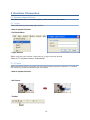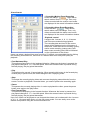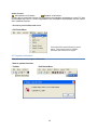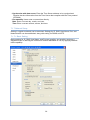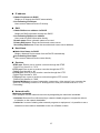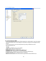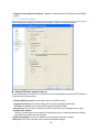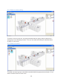
1
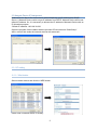
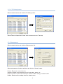
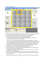
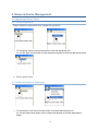
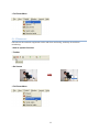
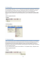
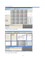
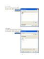
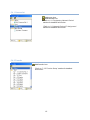
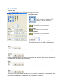
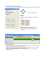
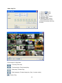
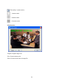
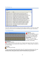
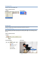
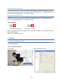
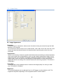
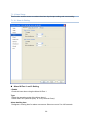
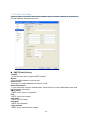
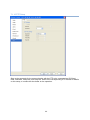
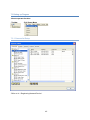
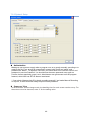
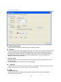
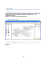
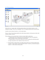
User’s Manual eVideoClient 16Channel Please read this manual thoroughly before use, and keep it handy for future reference. Design and specifications are subject to change without notice. Table of Contents 1. Introduction of Program ...................................................................................................... 1 2. Preparations before operating ............................................................................................ 1 2.1 Minimum System Requirements ................................................................................... 1 2.2 Installing eVideoClient................................................................................................... 1 2.3 Network Device IP Assignment ..................................................................................... 2 2.3.1 IP setting................................................................................................................. 2 2.3.2 Maintenance ........................................................................................................... 3 3. User Interface ..................................................................................................................... 4 4. Network Device Management............................................................................................. 5 4.1 Registering Network Device .......................................................................................... 5 4.1.1 Group Registration.................................................................................................. 5 4.1.2 Network Equipment Registration ............................................................................ 5 4.2 Connecting Network Device .......................................................................................... 6 4.3 Connecting Favorite ...................................................................................................... 8 4.4 Map ............................................................................................................................... 9 5. Real-time Observation ...................................................................................................... 10 5.1 Operation Network Device .......................................................................................... 10 5.1.1 Login ..................................................................................................................... 10 5.1.2 Freeze................................................................................................................... 10 5.1.3 Disconnect ............................................................................................................ 11 5.2 Screen Split ................................................................................................................. 12 5.3 Sequence Mode .......................................................................................................... 12 5.4 Control panel ............................................................................................................... 13 5.4.1 Camera list............................................................................................................ 15 5.4.2 Favorite................................................................................................................. 15 5.4.3 PTZ control ........................................................................................................... 16 5.4.4 Search list ............................................................................................................. 17 5.4.5 System log ............................................................................................................ 21 5.4.6 Camera status ...................................................................................................... 21 5.5 Program information.................................................................................................... 22 5.6 Program Exit................................................................................................................ 23 6. Record .............................................................................................................................. 23 6.1 Manual Recording ....................................................................................................... 23 6.2 Motion Event Recording .............................................................................................. 24 6.2 Alarm Event Recording ............................................................................................... 24 7. Setup................................................................................................................................. 24 7.1 Setting up Network Device .......................................................................................... 24 7.1.1 Video Setup .......................................................................................................... 25 7.1.2 Audio Setup .......................................................................................................... 27 7.1.3 Motion Setup......................................................................................................... 28 7.1.4 Alarm Setup .......................................................................................................... 29 7.1.5 Event Setup .......................................................................................................... 34 7.1.6 Date & Time Setup ............................................................................................... 35 7.1.7 Network Setup ...................................................................................................... 36 7.1.8 Maintenance Setup............................................................................................... 41 7.1.9 Record Setup........................................................................................................ 42 7.1.10 PTZ Setup........................................................................................................... 44 7.2 Setting up Program .................................................................................................. 45 7.2.1 Camera list Setup ................................................................................................. 45 7.2.2 System1 Setup ..................................................................................................... 46 7.2.3 System2 Setup ..................................................................................................... 47 7.2.4 System3 Setup ..................................................................................................... 48 7.2.5 Favorite Setup ...................................................................................................... 49 8. Appendix ........................................................................................................................... 50 8.1 MAP Editor .................................................................................................................. 50 8.1.1 Background image setting .................................................................................... 50 8.1.2 Device setting ....................................................................................................... 51 8.1.3 Alarm in sensor setting ......................................................................................... 52 8.1.4 Alarm out sensor................................................................................................... 52 1. Introduction of Program The PC program is used for operating multiple network devices. This program can be installed from the supplied CD-ROM disk. You can observe, record and playback up to 16 network devices in real-time, and there is no limit for the number of network devices to be managed. Registered network devices are managed according to their groups so that a number of network devices can be operated with efficiency. It also supports a variety of protocols for operating PTZ cameras and the device can be set through network. You can also use the scheduled recording function with date, time, alarm event and motion event, and playback recorded video in a fast and easy way searching by date, time or event. The program also provides improved operating conditions by utilizing intuitive and useful GUI configurations. 2. Preparations before operating 2.1 Minimum System Requirements CPU Pentium IV 3.0GHz (single core) or above RAM 1GB or above VGA ATI Radeon 9200(nVidia MX 440) or above HDD 80GB or above LAN 10/100 base T or above Monitor 1024 X 768 or above OS Windows XP DirectX DirectX 9.0c Web Browser Microsoft Internet Explorer 6.0 Minimum System Requirements Referring to the recommended system requirements to operate eVideoClient, check your operating PC system. If the system is less than the minimum requirements, PC may become slow while operating the program. 2.2 Installing eVideoClient 1. Double-Click install file in the eVideoClient folder in the supplied CD to start the installation. 2. Click ‘Next’ button to continue to the next step. 3. Click ‘Install’ button to start the installation. The installation may take a few minutes or more according to the system performance. After the installation, press ‘finish’ button to finish the installation. 1 2.3 Network Device IP Assignment Network Device that is first connected to network basically get IP address from DHCP Server. If Network Device could not get IP address from DHCP, Network Device will be set default IP address. So, it is necessary to allocate the IP address of Network Device with an IP allocation program. *Default IP address: 192.168.30.220 Open the program folder installed with the provided CD and execute “SmartSetup”. Wait a minute and seeks the network devices with automatic. 2.3.1 IP setting 2.3.1.1 Web button Select network device and click the ‘WEB’ button. Users enter a network device IP directly. 2 2.3.1.2 IP Setting button Select network device and click the ‘IP Setting’ button. Select Ethernet Adapter and users enter a network device IP directly. 2.3.2 Maintenance Select network device and click the ‘Maintenance’ tab. Select maintenance function radio box and click the ‘Submit’ button. Restart: Restart the network device. Userset: Initialize a user setting value of audio/video, alarm, etc. Restore: Restore all the values except a network-related setting to a basic value. Default: Restore all the setting values to a basic value. 3 3. User Interface 12 3 4 2 5 11 6 1 10 7 8 9 1. 2. 3. 4. 5. Splits: Is the split-screen window. Can be shown from one to 16 windows simultaneously. Screen: Is the window displaying video from the connected network device. Full Down Menu: Is the full menu functions required for the operation. Toolbar: Is the favorite menu functions required for the operation. Camera list: If users double-click a group on the ‘CAMERA LIST’ window, a list of registered network equipments will be displayed. Favorite: The Favorite is a user-defined connection list that combines more than one remote site, so multiple sites can be monitored at the same time with a single connection. Map: The Map panel allows efficient monitoring of the remote sites by displaying a map of the selectable site. When the device detects any event or the device is not working properly, the following status icons appear, and Popup dwell time window appears. 6. PTZ control: You can control and set up PTZ cameras with this function. 7. Alarm Out control: You can control Network Camera Alarm Out. 8. Search list: Users can Time-Laps search and play the image that is recorded manually (Option Motion Recorded, Alarm Recorded). 9. Camera status: This alarm, motion, recording icon turns on and off, if a event occurs. Display the mike and speaker used. 10. Log: This shows important events occurring during the program operation in real-time. 11. Event Search: Users can Event search and play the image that is recorded by (motion event, alarm event). 12. Minimize/ Maximize /Close Icon: Minimizes, Maximized, the window. Exit the program. 4 4. Network Device Management 4.1 Registering Network Device 4.1.1 Group Registration Before registering network devices, register the group first. 1. To add group, Use the left mouse button to click the add group icon. Or, use the right mouse button on the camera list window to click the add group button. 2. Enter a group name. 4.1.2 Network Equipment Registration 1. To add camera, Use the left mouse button to click the add camera icon. Or, use the right mouse button on the camera list window to click the add camera button. 5 Input a camera name. Input IP address. Default value. Default value. Use confirmation. Input a user ID. Input a user password. Use confirmation. Default value. 2. Enter a network equipment name to be used, IP address (or domain address), RTSP Port, HTTP Port, etc. into the entry window, and press the “Add” button to register a network equipment to group. *Enter a setting value correctly after checking it through a web browser. If an IP address (or domain address), RTSP Port and HTTP Port values are entered wrong, it cannot be connected to the network equipment concerned. *Refer to ‘2.3 Network Device IP Assignment’ section for detailed information. *Default RTSP Port Number is ‘7070’. *Default PTZ Port Number is ‘7000’. *Default HTTP Port Number is ‘80’. (HTTPS port Number is ‘554’) 4.2 Connecting Network Device Drag a network equipment to be connected and drop it on the screen. Users can see the real-time screen by dragging each network equipment and drop it on the desired screen. 6 Put a mark on a checkbox of network equipment to be connected, drag its folder to connect a range of checked network equipments at once. 7 4.3 Connecting Favorite The Favorite Sites panel displays the list of Favorite sites registered during eVideoClient System setup. Click Enter Name Selecting the Favorite site you want to connect to from the list and then dragging and dropping it in the desired position on the screen connects all remote sites registered in the Favorite site automatically. *Refer to ‘2.3 Network Device IP Assignment’ section for detailed information. 8 4.4 Map Open the map file. Close the map. *Refer to ‘8.1 MAP Editor’ section for detailed information. 9 5. Real-time Observation 5.1 Operation Network Device If the network device is connected properly, video is shown on the screen. 5.1.1 Login Check this item when showing login window. –How to operate function. • Full Down Menu • Login window When using the user account, users have to try log-in at every access. *Refer to ‘7.2.2 System1 Setup - Authorization’ 5.1.2 Freeze When the freeze button is pressed, the real-time monitoring screen is paused. To continue the monitoring, press the freeze button once again. –How to operate function. • On Screen. • Toolbar 10 • Full Down Menu 5.1.3 Disconnect Disconnect the network equipment under real-time monitoring, and stop its real-time monitoring. –How to operate function. • Toolbar • On Screen • Full Down Menu 11 5.2 Screen Split For the efficient observation, the screen-split function is provided. 6 modes are provided for the screen-split, which are 1, 4, 8, 11, 16-screen and Full-screen configurations. The mode can be selected in accordance with user’s observation method. Clicking the screen-split button at lower right of the screen changes the observation screen configuration. When you want to watch only the observation screen, you can select the full screen mode. You have only to click the ‘Esc’ key of the keyboard to return to the basic monitoring mode again. –How to operate function. • Toolbar • Full Down Menu 5.3 Sequence Mode In the 1-screen mode, you can watch the observation screens in sequence. The sequence mode can also be selected in the full screen mode. This function is activated when clicking the sequence mode button at lower right of the screen. To stop the automatic screen conversion mode, you can press the Sequence image button once again. You can set a dwell time for each screen at the automatic screen conversion mode, and skip a screen that you do not want to monitor. For more detailed setting, please see the ‘Refer to ‘7.2.2 System1 Setup – Sequence view.’ –How to operate function. • Toolbar 12 5.4 Control panel A fixing array of the control panel. A free array of the control panel. 13 • Load Layout Saved by reading the layout is applied. • Save Layout To save the layout set by the user. (Until 15.) 14 5.4.1 Camera list Add group icon. Add camera icon. *Refer to ‘4.1 Registering Network Device’ section for detailed information. *Refer to ‘2.3 Network Device IP Assignment’ section for detailed information. 5.4.2 Favorite Add favorite icon. *Refer to ‘7.2.5 Favorite Setup’ section for detailed information. 15 5.4.3 PTZ control -Control Tab You can control and set up PTZ cameras with this function. ▪ Pan/Tilt Control This is a button to adjust the PTZ camera in the four directions. ▪ FOCUS Control This button is for focus control. ▪ IRIS Control This button is for iris control. ▪ ZOOM Control This button is for zoom control. ▪ Pan/tilt Speed Control It sets a speed when adjusting the PTZ camera. The higher a value is, the faster a speed will be. ▪ Preset Import such value and press the “Go” button to move to the saved coordinate immediately. ▪ Auto Scan Enter a coordinate value of the start and end points, and set each zoom value to execute the Auto Scan from the start to end point values. ▪ Tour Execute an automatic monitoring mode with the combination of Preset and Auto scan values. ▪ Pattern This function can memorize all the paths of Pan/Tilt/Zoom operations for a defined time, and import their saved patterns to display on the screen again as they are. 16 -Menu Tab (OSD [On Screen Display]) Users can execute setup while seeing the PTZ camera menu on the common CRT screen. Used to move the menu. Used to increase and decrease various setting values. Execute the ‘Menu’, ‘Esc’, ‘Home’ and ‘CTRL’ buttons of the PTZ camera keyboard. Move to the setup screen for certain functions immediately. 5.4.4 Search list -Time-Lapse Search Users can search and play the image that is recorded manually or by events with date, time and recording conditions (motion event, alarm event). If users select a date and move the recorded network equipment to the screen, it will start playing the recorded image of the day from the beginning. * Red color is overlap video data area. If you will play recorded video, you can select overlap video data. 17 -Event Search 1. Searching Motion Event Recording Check the orange “ ” check box to search motion event recordings. Then, only videos recorded with the motion event mode are displayed in the record information window. 2. Searching Alarm Event Recording Check the blue “ ” check box to search alarm event recordings. Then, only videos recorded with the alarm event mode are displayed in the record information window. -Playback control It support the 1-screen, 4, 8, 11, 16-screen and full screen modes during playback. The recording date and time of the current image will be displayed on the left bottom of the screen, while the manual recording (green), motion event recording (orange color) and alarm event recording (blue) will be indicated on the right bottom of the screen. Users can select a desired time zone from 00 to 23, search a more detailed time by clicking the recording information bar, and move to a desired time zone easily and quickly for playback. ▪ Fast Backward Play This performs fast playing in the backward direction. Whenever the button is pressed, the play speed changes to 1, 2, 4 and 8X speed. When the forward button is pressed during the fast playing, the play speed decreases. ▪ Play This performs the normal 1X speed playing. When pressing this button in the forward-play, reverse-play or pause mode, the video changes to the 1X playing mode. ▪ Stop This stops the currently playing video and removes the playing network device from the screen. In order to playback a recorded video, you need to perform the searching again. ▪ Pause This pauses the currently playing video. In order to playback the video, press the pause button once again or the play button. ▪ Fast Forward Play This performs fast playing in the forward direction. Whenever the button is pressed, the play speed changes to 1, 2, 4 and 8X speed. When the reverse button is pressed during the fast playing, the play speed decreases. Up to four videos can be played at one time and the videos can be observed in the 1-screen or 4, 8, 11, 16-screen split mode, or in the full screen mode. You can easily move to the desired time position using the record information bar. 18 -Make Clip File 1. Click the button. 2. Select “Start”, “End”. 3. Select “Channel” 4. Click the “Save” button. 5. Input file name. 6. Click the “Save” button. * Click “Estimation” button, eVideoClient show video clip file size. Run screens of ClipViewer. : First stop, End stop. : Fast back play, Fast forward play. : Back play, Forward Play. : Back step play, Forward step play. (Only 1 screen mode.) : Pause, Play. 19 : Print (Only 1 screen mode.) : 1 screen mode. : 4 screen mode. : 16 screen mode. Print function. Original: Original image size. Print: Current screen print. Save: Current screen save to image file. 20 5.4.5 System log This shows important events occurring during the program operation in real-time. Up to 1000 system logs can be saved, and old-dated logs are deleted from the program automatically. 5.4.6 Camera status Alarm Event Alarm Event status When an alarm input event occurs, the alarm icon, located at upper right of the screen, blinks for the time period set in the network device setting. *Refer to ‘7.1.4 Alarm Setup’, ‘7.1.5 Event Setup’ for details on the Alarm, Event setting. Motion Event Motion Event status When a motion event occurs, the motion icon, located at upper right of the screen, blinks for the time period set in the network device setting. *Refer to ‘7.1.3 Motion Setup’ for details on the motion setting. Recording Recording on/off status In order to save the real-time observation video to PC, press the recording button. The realtime observation video current shown is recorded and saved to PC. For the method of recording, search and playback, please see the ‘6 Record/Search/Replay Video.’ 21 Audio Control Microphone on/off status Speaker on/off status If users are to control the volume of a microphone and speaker connected to a user PC, they should adjust the user PC volume regardless of the microphone and speaker volume control set in Network Devices. –A control panel hidden and show. • Full Down Menu Check this item when showing control panel. The control panel to hidden, Uncheck the button once again. 5.5 Program information Click this item to see program information. –How to operate function. • Toolbar • Full Down Menu 22 5.6 Program Exit Click this item to see program Exit. –How to operate function. • Toolbar • Close button. 6. Record Record an image under real-time monitoring to the HDD of users PC. 6.1 Manual Recording When clicking the recording button during the real-time observation, the color turns to red and the recording starts. When pressing the recording button again, this recording process will stop. –How to operate function. • Toolbar • Full Down Menu • On Screen 23 6.2 Motion Event Recording If a motion event occurs, it can be recorded automatically through this setting process. For motion event recording, execute the motion event setting (See the“7.1.3 Motion Setup”), and try the record setting (See the “7.1.9 Record Setup”). 6.2 Alarm Event Recording If an alarm event occurs, it can be recorded automatically through this setting process. For alarm event recording, execute the alarm event setting (See the “7.1.4 Alarm Setup”), and try the record setting (See the “7.1.9 Record Setup”). • Record Mode Overwrite record mode Record once mode Before recording, check the remaining amount and the recording course and the overwrite item of the hard disk. *Refer to ‘7.1.9 Record Setup’ 7. Setup 7.1 Setting up Network Device Currently the setup window which corresponds to the network equipment which is connected appears. –How to operate function. • On Screen • Setup Window (pop up) 24 7.1.1 Video Setup Image Appearance Resolution It enables users to determine a basic screen size when having an access through the Web Browser or PC program. The screen size control comes in four modes like D1, 640 X 480, 320 X 240, and 160 X 128. Users can reset the selected screen size anytime while monitoring the screen on a realtime basis. Compression When it is necessary to adjust a smooth transmission status according to network situations, users can increase the compressibility to carry out the network transmission stably. On the other hand, when it is necessary to maintain a detailed monitoring screen by enhancing the image quality, users can do so by decreasing the compressibility. In ease case, please adjust this function according to the network status and monitoring purposes. The default is 2000(Kbps). Image filter The image filter control enables users to reinforce the image quality in a strong or weak way. The default is "disabled.” Brightness The screen brightness can be adjusted from 0 to 255 stages, and the default is 128. The brightness may differ depending on the equipment and PC monitor status. 25 Contrast The screen contrast can be adjusted from 0 to 127 stages, and the default is 73. The contrast may differ depending on the equipment and PC monitor status. Saturation The screen saturation can be adjusted from 0 to 127 stages, and the default is 64. The saturation may differ depending on the equipment and PC monitor status. MPEG4 Video Stream Frame rate Upon the real-time play, users should select a frame refresh rate per second. If the rate is high, the image will become smooth. On the other hand, if the rate is low, the image will not be natural but it can reduce a network load. Profile SP (Simple Profile) is available up to the CIF resolution and 384kbit/s. ASP (Advanced Simple Profile) is available up to the 4CIF resolution and 8000kbit/s. Bit-rate control Variable bit rate (VBR): It refers to the type of using a variable bit rate (VBR). Increase a bit rate for the image with much motion, and decrease a bit rate for the image with little motion. The basic setting value is a VBR type. Constant bit rate (CBR): Using a constant bit rate (CBR) may guarantee a stable play. However, if a large amount of data is not required, it may cause the waste of a transmission rate. If a large amount of data is required, it may cause the image quality to be decreased. GOV size Enter the GOV (group of VOP) size. If users want to have a high quality of fast image one by one, please decrease the value. For the purpose of general monitoring, please do not change a basic value. Such act may cause a problem to the system performance. For the details of GOV setting, please contact the service center. 26 7.1.2 Audio Setup Audio Setting □Enable Check this item when using the Audio. Compression type Users can increase a transmission rate or enhance a tone quality by selecting an audio compression mode. The PCM 16-bit implements the best tone quality, while the PCM 8-bit corresponds to that of radio sound. Sample rate If a sample rate is low, the tone quality will go down but the transmission rate will go up. If a sample rate is high, the tone quality will be better, but the transmission rate will drop. Please, adjust its rate in accordance with a network status or purposes. Audio Input / Output Source Users can select either MIC input or LINE input, but cannot use both at once. Input Volume Users can control the input volume by adjusting the microphone volume. Output Volume Users can control the output volume of the speaker connected to the Network Dome Camera. 27 7.1.3 Motion Setup Motion Detection Setting Motion information is processed by splitting the screen into 64 areas. Each area can be selected by clicking with the mouse, and green point shown in the selected area. The area which uses the motion information as an event is shown green point, while the area which does not use the information is indicated empty. □Enable Check this item when using the motion information. Sensitivity This sets up the sensitivity for the motion detection. Motion dwelling time This sets up the event dwelling time when a motion occurs. This can be set in the range of 0 ~ 6 seconds. When an event occurs, the motion icon at the upper right blinks in red for the preset time period. When another motion occurs during the motion event, the dwelling time is extended on the basis of the occurring time of the second event. Enable down FPS This feature decreases frame rate to about 1 FPS when no motion event occurs, while operates with the frame rate set in this item when a motion event occurs. 28 7.1.4 Alarm Setup This function enables users to conduct the alarm input/output setting and event setting. 7.1.4.1 Alarm In Setting Alarm IN Port 1 and 2 Setting □Enable Check this item when using the Alarm IN Port 1. Type Select the operation mode of the Alarm Input 1. Select either ‘N.O.(Normal Open)’ or ‘N.C.( Normal Close)’ Alarm dwelling time Designate a running time for alarm occurrence. Select one out of 0 to 180 seconds. 29 7.1.4.2 Alarm Out Setting Upon the alarm occurrence, this function enables users to receive a mailing or ftp service to the mail address designated by users. SMPT(Email) Setting □Enable Check this item when using the SMTP (eMail). Sender Enter an eMail address to send a mail. Receiver list Enter up to 10 eMail addresses to receive a mail. Use authentication If your mail server requires authentication, check the box for Use authentication and enter the necessary information. SMTP server SMTP server name or IP address. Port SMTP server port number. User name SMTP user ID (name) Password SMTP user password Login method SMTP server authentication method 30 7.1.4.3 FTP & JPEG Setting FTP Settings □Enable Checks to activate the FTP function. □Passive mode Checks to connect the passive connection FTP. Sender name or IP Enters the FTP IP address or host name to be received. Port Enters the port number of FTP to be received. Remote Directory Enters the location for saving the file of FTP to be received. Username Enters the user's account when connecting to FTP. Password Enters the user password for connecting to FTP. □Anonymous login Includes any user account that program did not authenticate. 31 JPEG Settings Sets up the creation condition, screen size, color and name of JPEG file to be sent to FTP. Pre event Creates the JPEG file of chapter 1~5 for 1~2 seconds before the event is generated. Post event Creates the JPEG file of chapter 1~5 for 1~2 seconds after the event is generated. Image size Selects the size of JPEG file to be created among 160X120 and 320X240. Color Selects the color or B&W of JPEG file to be created. Base name Write in the basic name of file to be created. Except for the basic name, It is possible to add supplementary names for discriminating multiple files. Additional suffix Selects one among date, time and the number of sequence created. ◎None: Do not add supplementary names. ◎Date Time: Adds the date and time when the file was created behind the basic name. ◎Sequence: Adds the number in sequence of file creation behind the basic name. 32 7.1.4.4 Preset Setting PRESET Setting □ Enable: Checks to activate the PRESET function. Alarm Input port 1: Alarm Input 1 about PRESET number to select. Alarm Input port 2: Alarm Input 2 about PRESET number to select. 33 7.1.5 Event Setup IN-OUT Mapping By connecting the Alarm OUT operations to the events occurred from the Alarm IN, users can send an eMail or FTP Server. Alarm IN - Alarm IN comes in Motion, Alarm in port 1 and Alarm in port 2. Alarm OUT □Alarm: Operate the equipment connected to the Alarm OUT port to the events occurred from the Alarm IN. □Email: Send an email to events occurred from the Alarm IN. □FTP: Sends the captured picture to FTP by the event which occurs from Alarm input. □PRESET: Operate the PRESET by the events occurred from the Alarm IN. □Enable mandatory alarm out -Enable alarm control to open/close contact. 34 7.1.6 Date & Time Setup Date & Time Current Time Indicate a current time. Date: Indicate a current day, month, and year. Time: Indicate a current second, minute, and hour. Time Zone Select a time zone to be used. Automatically adjust for daylight saving time changes: Check it if users are to apply the Summer Time. New Time ◎Synchronize with computer time: Synchronize the time with that of a current user computer. ◎Synchronize with NTP server: Synchronize the time with that of the NTP server. Receive the time information from the NTP RFC2030) server. 35 ◎Synchronize with date server: Enter the Time Server address to be synchronized. Receive the time information from the Time Server that complies with the Time protocol (RFC868). ◎Set manually: Users enter a current time directly. Date: Enter a current day, month, and year. Time: Enter a current second, minute, and hour. 7.1.7 Network Setup Setting in regard to network can be executed. Settings for IP, DNS, Host Name, Port, and Network traffic can be established, along with setting for DDNS and RTP. 7.1.7.1 Basic Setting Basic settings for IP, DNS, Host Name, and Port are possible, and possibly works as a adjustment role in reducing the overload of network bandwidth in use, by applying Network traffic capability. 36 IP address ◎Obtain IP address via DHCP Obtain an IP through the DHCP automatically. ◎Use Following IP address Users enter a Network Device IP directly. DNS ◎Obtain DNS server address via DHCP Obtain the DNS information through the DHCP. ◎Use Following DNS server address Users enter the DNS information directly. Domain name: Enter a domain name to be used. Primary DNS server: Enter the first domain name server. Secondary DNS server: Enter the second domain name server address. Host Name ◎Obtain Host Name via DHCP Obtain a Network Device name from the DHCP automatically. ◎Use Following Host Name Users enter a Network Device name directly. Services RTSP port: Enter a port to receive a service through the RTSP. *Default Port Number is ‘7070’. HTTP port: Enter a port to receive a service through the HTTP. *Default Port Number is ‘80’. HTTPS port: Enter a port to receive a service through the HTTP. *Default Port Number is ‘554’. PTZ port: Enter a port to receive a service through the PTZ control. *Default Port Number is ‘7000’. External WAN port: In case of connecting a camera(or .video server) from a remote site with Port Forwarding function in IP Sharing device, enter port number that set in ‘Port Forwarding’. Network traffic Maximum bandwidth Set a limitation on user network resources by designating the maximum bandwidth. ◎Unlimited: Selected if not influenced by a network-related program or equipment without a limitation on the network bandwidth. ◎Limited to: In case of sharing other network programs or equipment, it is possible to set a limitation on the maximum bandwidth in the unit of Mbit/s or kbit/s. 37 7.1.7.2 DDNS Setting Internet Dynamic DNS When using the high-speed Internet with the telephone or cable network, users can operate the Network Device even on the floating IP environment in which IPs are changed at every access. Users should receive an account and password by visiting a DDNS service like http://www.dyndns.com/. □Enable Check to get DDNS service to be available. DDNS Server: Select the DDNS server. Registered host: Enter an address of the DDNS server. Username: Enter an ID to access to the DDNS server. Password: Enter a password to be used for accessing the DDNS server. Password Confirm: Enter a password again to confirm it. Maximum time interval: Set a time interval to synchronize with the DDNS server. 38 □Register local network IP address: Register a Network Device IP address to the DDNS server. 7.1.7.3 RTP/RTSP Setting Have a setting for sending and receiving an audio or video on a real-time basis. Stream RTP after camera start-up Enter a destination IP and Port to send movie data automatically through the RTP while the Network Device has booting. ◎Send to DHCP server IP: Send movie data to the DHCP server. ◎Send to IP(Client): Send movie data to other certain destination addresses. RTP Port: Available from 1024 to 65532, and the default is 5000. ◎Do not send: Do not send a stream to the RTP client until it is requested from a client. □Enable multi stream Check it to send data for the purpose of saving them into an external extension storage right after the Network Device operates. Send to secondary: Enter an IP address of the external extension storage. RTP port: Enter a Port number of the external extension storage. 39 The Port number to be used is [1024 ~ 65532]. Frame rate: Indicate a frame rate that is sent to the external extension storage when the multi stream works. Once the multi stream function is checked, the MPEG profile setting will be changed to the Advanced Simple Profile. RTSP/RTP settings Perform a multicast setting to send a video and audio to multiple users. (Up to 10 users) ◎Disable Multicast Do no use the multicast. ◎Enable Multicast Use the multicast. Multicast destination IP: Enter an IP between 224.0.0.0 and 239.255.255.255. Although it is empty, an IP will be entered automatically. RTP port: Enter a value between 1024 and 65532. RTP TTL: Enter a value between 1 and 255. If a network status is smooth, enter a lower value. On the other hand, if a network status is poor, enter a higher value. When there are many Network Devices or users, a higher value may cause a heavy load to the network. For a detailed setting, please consult with a network manager. 40 7.1.8 Maintenance Setup Maintain Server Restart: Restart the Network Device. Userset: Initialize a user setting value of audio/video, alarm, etc. Restore: Restore all the values except a network-related setting to a basic value. Default: Restore all the setting values to a basic value. Upgrade Server Carry out the upgrade by importing an upgrade file and pressing the ‘Upgrade’ button. During the upgrade, do not turn off the power of the Network Device. And try an access again after waiting five minutes or longer. Backup Save a setting value that users enter to the Network Device, to a user PC. Restore Import and apply a setting value saved to a user PC. 41 7.1.9 Record Setup 7.1.9.1 Record Setting Sets up items related with recording or saving the real-time observation video. Recording Setting Pre record Pre-record can be set up. You can set up a value between 0~6 seconds for the pre-record. Event Can record with a condition of alarm input or motion. Also, post-record can be set up. You can set up a value between 0~180 seconds for the post-record. 42 7.1.9.2 Schedule Setting □Enable schedule record Allow an automatic recording by time schedule. First, select a recording condition among Manual, Alarm, and Motion, putting check on the time per day. Implement an automatic recording by day and time based on the conditions checked. 43 7.1.10 PTZ Setup Sets up the protocols for the communication with the PTZ to be connected and ID, Baud Rate, Data Bits, Parity Bits, and Stop bits. Refer to the corresponding PTZ manual for details on the setup, or contact with the dealer on the operation. 44 7.2 Setting up Program -How to operate function. *Toolbar *Full Down Menu 7.2.1 Camera list Setup *Refer to ‘4.1 Registering Network Device’. 45 7.2.2 System1 Setup Authorization Manage a user account to apply when a program runs or to permit manually recording or to make a clip file. First, account is automatically created, with first ID as “admin” and password as “admin”. To register a new user, you should enter ID to use into User ID and password to use into Password. You should enter the same password once again on Confirm, before appointing a user Level. Administrator can get access to all the program features, while User has SETUP feature inactivated. * If you check “Always check ID to begin recording manually” and make Manual Recording or Clip file, e-Video Client will always request ID and password. Sequence View In the automatic screen change mode, the dwelling time for each screen can be set up. For the screen not to be observed, enter ‘0’ for the setting value. 46 7.2.3 System2 Setup Date & time format Select from this item when changing sign form of date and time. Record Possibly set HDD write mode which saves image. The “Once” mode stop the recording and allow no further storage, when HDD storage space is not secured during the storage of real-time control image, while the “Overwrite” mode doesn’t stop the recording and delete the oldest file to keep on saving, when HDD storage space is not secured during the storage of real-time control image. Base file name Specifies a folder to store the recorded video. When pressing the setup button, file name can be created. Check Box: When the record file is full, show message. Language It will be able to select a user language. The type of language it will be able to select is the English, the French, the German, the Spanish and the Italian. OSD □Enable OSD Text Check this item when showing an information of Network Device name and channel number etc. on the screens. 47 7.2.4 System3 Setup Popup window When the event occurs in popup window shows. Set up eVideClient to sound when events are detected by selecting events from the list and designating the sound file (.wav) path. Select event type Alarm and Motion. 48 7.2.5 Favorite Setup Favorite The Favorite is a user-defined connection list that combines more than one remote site, so multiple sites can be monitored at the same time with a single connection. Camera: You can arrange the camera on the view screen. Favorite: It can be selected both the Auto-Connection and the Auto-Playback. Auto connection: As the eVideoClient is implemented, it is connected the cameras automatically. Playback: Selected image can be played back on the eVideoClient Add: Add favorite in the favorite list. Modify: Modify favorite in the favorite list. Delete: Delete favorite from the favorite list. Clear: Clear camera on the selected screen. Clear All: Clear all cameras on the all screen 49 8. Appendix 8.1 MAP Editor Run the program by selecting MapEditor from eVideoClient program under the start menu in windows. First you should save mec file by selecting File->Save MEC File so that eVideoClient can read this. Maximum 16ch camera can be registered with Map editor. 8.1.1 Background image setting With option menu for Background image setting, you can set height ,width of image and popup dwell time. Popup dwell time: in this option menu to set the duration of the map popup screen displayed when events are detected, and the following Popup dwell time window appears. 50 8.1.2 Device setting Select the icon in camera taps, and drag and drop them at the desired locations on the background image. Then you can setting IP, Port, ID, Password and event for each camera. channel: set the channel number (1~16) for each device. Group: in case of connecting together server with analog camera, set the group number with channel number of server. Event setting: you can select alarm in event or mouse click for watch view. 1. Selecting click from a drop down list and checking the watch view popup box pops up another screen by clicking the mouse button. 2. Selecting alarm in event from drop-down list and checking the watchview popup box pops up another screen when an alarm event occur. Ú Group number is using to figure out which camera has been connected with camera or sensor. If alarm sensor is connected with channel 1 camera, you should set group number 1 in alarm sensor setting menu. 51 8.1.3 Alarm in sensor setting The Alarm in device group No. should be associated with the popup camera channel as a same group to use the popup function. Then you can select the setting for watchview when an alarm in event occur. 8.1.4 Alarm out sensor The alarm out sensor group no should be associated with the popup camera channel, to use alarm out device when an event occur. 52 User’s Manual eVideoClient 16Chennel