1
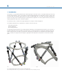
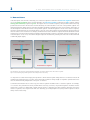
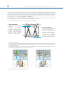
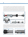
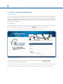
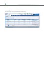
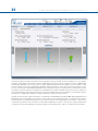
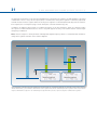
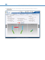
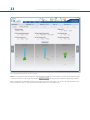
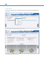
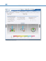
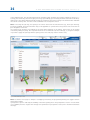
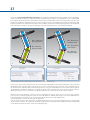
SOF TWARE USER’S GUIDE
Software User’s Guide
Software Version 1.3
1.INTRODUCTION
1
2.NOMENCLATURE
2
3.USER ACCESS AND ACCOUNT MANAGEMENT
6
3.1 OBTAINING ACCESS
6
3.2 LOGIN SCREEN
6
3.3 HOME PAGE
7
4.PATIENT AND CASE MANAGEMENT
8
4.1 MENU STRUCTURE
8
4.2 ADD A NEW PATIENT 9
4.3 LIST OF PATIENTS
11
4.4 ADD A NEW CASE
12
4.5 VIEW CASES
13
4.6 SEND A CASE
14
4.7 ARCHIVE A CASE
15
5.CASE PLANNING
17
5.1 CASE DATA
17
5.2 DEFORMITY PARAMETERS
17
5.3 FRAME PARAMETERS
23
5.4 POSTOPERATIVE
29
5.5END OF CORRECTION
33
5.6SCHEDULE
34
5.7REPORT
35
5.8 CHECKUP
42
6.WEBSITE NAVIGATION
45
6.1CHANGE PASSWORD
48
6.2 PRESCRIPTION PREFERENCES
49
Orthofix wishes to thank the following surgeons for their contribution
to the development of this User’s Guide:
Franz Birkholtz, M.D.
Alexander Cherkashin, M.D.
Mikhail Samchukov, M.D.
William Terrell, M.D.
TL-HEX Software User’s Guide: Software version 1.3
The applicable End User License Agreement can be found at http://tlhex.com/policies/Eulapolicy.html
The applicable privacy policy can be found at http://tlhex.com/policies/privacypolicy.html
Security Precautions:
User is advised to clear the browser history (temporary Internet files, cookies, etc.) after logging out of the TL-HEX
application.
Computer System Requirements
Display Settings:
Screen resolution of 1024 x 768 Pixel or higher.
Supported Browsers:
Microsoft Internet Explorer®: Version 8 or 9
Microsoft and Internet Explorer are either registered trademarks or trademarks of Microsoft Corporation in the United States and/or other countries
Internet Connection:
High-speed Internet connectivity is recommended.
Language Setting:
Select the “Language” setting in the Internet Explorer browser for the country of origin. This will provide the correct date
setting.
My Username:
My Password:
My Email Address:
II
T L- H E X S O F T WA R E US E R ’ S G U I D E (S o f t w a r e v e r s i o n 1. 3)
LOG IN
The following provides a sequential overview of the process for a case management with TL-HEX software
Obtain an account at
www.tlhex.com
following the onscreen instructions
Access to the TL-HEX software is controlled by Username and Password.
These can be obtained at www.tlhex.com by requesting a new account and
following the onscreen instructions.
# see 3.1 Obtaining Access
Log in the TL-HEX software
https://app.tlhex.com
Enter a valid Username and Password in the appropriate text fields and click
Sign In to gain access to the software.
# see 3.2 Login Screen
Create a New Patient
In the Add New Patient screen, create a new patient if the patient doesn’t exist.
Each case must be linked to an existing patient.
# see 4.2 Add a New Patient
PREOPERATIVE
Create a New Case
related to a patient
Specify the Deformity Parameters
Indicate the Frame Parameters
POSTOPERATIVE
If the frame is
not pre-assembled,
go directly to the
Postoperative
phase
Complete the Mounting Parameters section
to pre-assemble the frame
To start a new treatment, create a new case. Select patient from the ones
available in the drop-down list providing the information required (Case Name,
Case Number, Side, Bone Type).
# see 4.4 Add a New Case
Describe the deformity starting from the reference segment identification.
Then, provide the relevant parameters relative to the angular deformity,
rotation, translation and bone length discrepancy.
# see 5.2 Deformity Parameters
Indicate the ring type and size that will be used for the frame.
# see 5.3 Frame Parameters
If desired, complete this section with details of the planned frame position,
relative to either the deformity apex or the osteotomy/fracture level. Strut types
and lengths are being suggested.
# see 5.3 Frame Parameters
Confirm or adjust postoperative
values and struts configuration
Provide the actual frame parameters and position as mounted and adjust/
modify the struts configuration to adapt them to the configuration obtained
during the surgery.
# see 5.4 Postoperative
Visualize the end of correction parameters
providing added over/under correction,
if required
Visualize the expected results at the end of correction.
If necessary, specify the eventual over/under correction parameters to be
considered in the treatment.
# see 5.5 End of Correction
Determine the schedule for
the correction planning
Define the schedule by specifying the latency period, the maximum rates and
speeds of correction or the desired days of correction.
# see 5.6 Schedule
Visualize and print the report
Visualize and print the prescription for
the patient
Use the checkup function to create
a new case starting from
the date-selected parameters
Once all data is approved by the surgeon, the schedule will be calculated
and the prescription is generated. The prescription can be saved and a hard
copy will be given to the patient. For each correction step, the number of
turns the patient must make are indicated for each strut for both acute and
gradual adjustments. A hard copy of the bill of materials and the report may
be generated. The report is a more detailed view for the surgeon indicating
the length settings for the gradual and acute setting on the strut.
# see 5.7 Report
Surgeon can use the checkup function to generate a new case starting from
a specific date of the treatment. This new case will report all the parameters
updated to the selected date. The Surgeon can then proceed to setup a new
deformity correction treatment.
# see 5.8 Check up
1
INTRODUC TION
1. Introduction
The TL-HEX is a circular external fixator based on Ilizarov principles. This frame consists of a hexapod made up of two rings
(circular external supports - Fig.1), one ring and one foot plate (U shaped plate for foot deformity correction - Fig.2) or two
foot plates with the opening in opposite directions and six variable-length struts. The relative strut lengths determine the
position of the rings in space. Because the rings are attached to bone segments or to a bone segment and foot, their position
indirectly determines the position of the bone segment.
The Software is able to calculate strut length adjustments for surgeon’s review and approval.
The software needs three sets of parameters to calculate correction. These are:
1) deformity parameters
2) frame parameters
3) mounting parameters
The deformity parameters define to the software what the deformity or fracture displacement looks like. The second set of
parameters describes the size and shape of the frame that is to be used. The third set of parameters designates where the
frame’s reference point is in relation to the fracture or deformity area. With these sets of parameters the software will be
able to calculate, for surgeon review and approve, appropriate strut adjustment for the patient to achieve the treatment
goals.
Fig.1
Fig.2
Fig.1 TL-HEX standard application with two rings and 6 variable length struts
Fig.2 TL-HEX application with one ring, one foot plate and 6 variable length struts (foot deformity correction)
2
T L- H E X S O F T WA R E US E R ’ S G U I D E (S o f t w a r e v e r s i o n 1. 3)
2.Nomenclature
In the description of the fracture or deformity, one of the bone segments is defined as the reference segment and the other
one as the moving segment. In the software diagrams, the reference segment is indicated as a blue segment, and the
moving (non-reference) segment as green. The surgeon chooses a reference segment, either proximal or distal. Choosing
proximal reference means that the frame and the deformity are oriented relative to the axis of the proximal segment. The
deformity parameters (what the bone looks like) should be described accordingly. Therefore, the translation and rotation of
the distal segment is described in relation to the proximal segment. If the distal segment is chosen as the reference segment,
the frame and the deformity are orientated relative to the axis of the distal segment and measurements would need to be
taken in relation to this orientation. For example, medial translation of the distal bone segment would be described as lateral
translation because the proximal segment would be translating laterally in relation to the distal (reference) segment (Fig. 3).
In the description of foot cases, the software diagram represents the deformity following the same rules as above but with
a dedicated graphic (Fig.4).
Proximal Reference Segment
Proximal Reference Segment
Lateral Translation
Medial Translation
Medial Translation
Distal Reference Segment
Fig. 3
Fig. 4
Fig. 3 Description of moving bone segment translation depending on proximal or distal location of the reference segment.
Fig. 4. For foot deformity, the proximal segment is almost always used for referencing.
It is important to realize that changing from proximal to distal referencing will change direction of translation in both AP
and ML views and the direction of rotation in the Axial view, but will not change length or angulation parameters because
these are mathematically independent of the point of reference.
To minimize measurement errors on the x-rays, the shortest segment should be used as a reference segment. For example,
if a correction was performed around a proximal tibial osteotomy or fracture, the proximal segment should be used for
referencing. If surgeon is dealing with a distal femoral fracture or deformity, the distal segment should be used as the
reference segment, if the surgeon works with foot deformity, (for example Equinus foot) the proximal segment is almost
always used for referencing.
3
T L- H E X S O F T WA R E US E R ’ S G U I D E (S o f t w a r e v e r s i o n 1. 3)
There are three diagrams in the software. The first diagram is the AP view diagram corresponding to the standard AP
x-ray of the limb. The second diagram is the ML view diagram representing the standard ML x-ray of the limb. There are
orientation keys on these two diagrams that indicate the medial/lateral and anterior/posterior aspects, respectively. The third
diagram is the Axial view diagram representing the view we would have when looking either up or down the limb from the
reference segment. On this diagram, the orientation keys are anterior, posterior, medial, and lateral (Fig. 5).
a
b
c
Fig. 5. Standard AP view (a), ML view (b) and Axial view (c) software diagrams. The proximal (reference) segment is indicated in blue and the distal (moving)
segment in green. There is valgus-procurvatum deformity of the limb as evidenced by the direction of angulation on the AP view. The frame is comprised of
two rings interconnected by 6 struts. In all three diagrams, the ring orientation is marked with red dots.
Fig. 6. Standard AP view (a), ML view (b) and Axial view (c) software diagrams. The proximal (reference) segment is indicated in blue and the distal (moving)
segment in green. There is procurvatum deformity of the foot as evidenced by the direction of angulation on the AP view. The frame is comprised of one ring
and one foot plate. In all three diagrams, the ring orientation is marked with red dots.
4
T L- H E X S O F T WA R E US E R ’ S G U I D E (S o f t w a r e v e r s i o n 1. 3)
The struts are attached to full rings, 5/8 rings or foot plates in pairs using special angulated tabs around the circumference
of the external support. Each full ring or foot plates has 3 working tabs, which will have struts attached to them and three
non-working tabs. Each 5/8 ring has 3 working and 2 non-working tabs. The footplate will have 3 working tabs. For proper
identification, the struts are numbered using color number clips. The clips are numbered from 1 to 6 and color coded as red
(1), orange (2), yellow (3), green (4), blue (5), and purple (6).
The new 3/8 component, allows for transforming a 5/8 into a full ring. In case of need this component can be added also
after the surgery. It has one tab, working or non-working depending on the case.
The struts are numbered by the surgeon, according to the following rules:
The RING ORIENTATION
- is the tab from which struts 1 and
2 orginate
- is important to determine the way
the frame is rotated around the
limb when referencing proximally
- is always on the proximal ring,
regardless of which segment is
chosen as the reference segment
The RING ORIENTATION
- is the tab on the distal ring situated
opposite to the proximal one
- is important to determine the way
the frame is rotated around the
limb when referencing distally
- is always on the distal ring,
regardless of which segment is
chosen as the reference segment
• 5/8 Rings open medially
- For a 5/8th ring open medially on the proximal reference limb segment, with no rotational defect, the ring orientation is
the nearest angulated end tab that is anti-clockwise from the anterior point of the limb. The anti-clockwise rotation is for
both right and left limbs.
- The ring orientation tab rotation is always anti-clockwise, which means for the left limb there is an “external” rotation value and for the right limb there is an “internal” rotation value.
• The rotational values are automatically calculated
5
T L- H E X S O F T WA R E US E R ’ S G U I D E (S o f t w a r e v e r s i o n 1. 3)
The software will create a prescription, for surgeon review and approval, indicating direction and daily amount of adjustment
for each strut. TL-HEX struts (Fig. 7) consist of two telescoping aluminum tubes, an outer tube (A) and an inner tube (B),
which can be locked together at various lengths using the side locking bolt (C) and clamp washer (D). The inner tube is
attached to a spring-loaded, black knurled adjustment knob (E). The adjustment knob mates with the threaded rod (F) in a
manner such that the rod translates relative to the inner tube when the knob is rotated. This will provide gradual changes
of overall strut length in 0.5-mm increments. Each strut has two special joints (G,H), one at the base of the outer tube (tube
end joint) and the other at the end of the threaded rod (rod end joint). Each joint has a mounting stud (I, J), which can be
inserted into the mounting holes on the ring tabs and held in place by the locking screw. The new UltraShort strut has a
different design in order to be applied in special cases (very severe angular deformity, extreme Equinus foot, etc.). Anyway
the most important features (two telescoping tubes, the adjustment knob and the locking bolt) have been preserved (Fig. 8)
J
I
A
B
F
G
H
E
D
Fig. 7. TL-HEX strut structure.
C
Fig. 8 TL-HEX ultra-short strut structure
The TL-HEX struts allow performing acute and gradual adjustment. The acute adjustment of the strut length is achieved by
untightening the side locking bolt, sliding the inner tube relative to the outer tube to the desired length and re-tightening
the locking bolt. Acute adjustment is indicated by the inner tube scale in 1-mm increments relative to the orange-line mark
on the outer tube (Fig.9 a). The gradual adjustment is achieved by pulling and rotating the adjustment knob resulting in a
noticeable detent (tactile click) every 0.5 mm of adjustment. Gradual adjustment is indicated by the same scale relative to
the green-line mark on the end of the threaded rod (Fig.9 b). The direction of adjustment is indicated by the direction clips.
The arrow of the direction clips is oriented according to the prescription (see details in General Principles of TL-HEX Frame
Assembly, TL-1405-OPT-E0-B).
a
Fig. 9. Indicators for acute (a) and gradual (b) adjustments on the TL-HEX struts.
b
6
T L- H E X S O F T WA R E US E R ’ S G U I D E (S o f t w a r e v e r s i o n 1. 3)
3. User Access and Account Management
3.1 Obtaining Access
Access to the TL-HEX software is controlled by an Username and Password. The username and password can be obtained at
www.tlhex.com by requesting a new account from the Home Page and following the onscreen instructions. Upon a request
being received by Orthofix, it will be validated to confirm whether the applicant has undergone the necessary training to use
the system safely and responsibly. Once approved, the surgeon’s user account will be activated, and Username and Password
will be emailed to the applicant.
3.2 Login Screen
The TL-HEX application is located at: http://app.tlhex.com. This location provides the Login screen (Fig. 10 ). Enter a valid
Username and Password in the appropriate text fields, and click Sign In to gain access to the software.
Click “Forgot your Username or Password?” link to retrieve username or to reset the password.
Fig. 10. TL-HEX software Login screen.
To reset the password, user is asked to provide the username in the relevant field and click Reset Password .
A new password is generated and sent by email.
To retrieve or restore the username, user needs to contact directly the TL-HEX Customer Care ([email protected]).
Note: the release 1.2 will be maintained to serve the countries where the new release 1.3 has not been approved yet.
7
T L- H E X S O F T WA R E US E R ’ S G U I D E (S o f t w a r e v e r s i o n 1. 3)
3.3 Home Page
After a successful login, the user accesses directly the list of patients (Fig. 11).
Fig. 11. TL-HEX software Home Page.
8
T L- H E X S O F T WA R E US E R ’ S G U I D E (S o f t w a r e v e r s i o n 1. 3)
4. Patient and Case Management
4.1 Menu Structure
Patient and Case menus include a list of patients or cases and allow the surgeon to add a new patient or case, respectively.
All cases are related to a patient (Fig. 12). Therefore, a new patient must be created prior to beginning a new case. There are
no restrictions on the number of cases that can be associated with each patient.
Case 1
Patient A
Case 2
Case 3
Case 1
Patient B
Case 2
Fig. 12. Patient and Case management menus and structure.
9
T L- H E X S O F T WA R E US E R ’ S G U I D E (S o f t w a r e v e r s i o n 1. 3)
4.2 Add a New Patient
Patient g Add New Patient
All patients are entered into the system through the Add New Patient menu. The
Add New Patient
button can be
used either in the List of Patients or List of Cases screen. For each new patient (Fig. 13), surgeon should assign a Patient ID,
insert Patient Initials (or other reference associated with this patient) and select patient Gender. Optionally user can associate
to a patient specific “Prescription Notes” and a “Prescription Address” expanding the “Prescription Preferences” menu (Fig. 14 )
(see 6.2 Prescription Preferences for details about setting addresses). Clicking on “Save Patient” will complete the creation process
and open the “List of patients” screen, which will include all previously entered patients as well as the newly created one.
On the other hand, clicking on “Save & Create Case” will save the new patient and will open a new ready-to-use case already
associated to the newly created patient (Fig. 15).
Fig. 13. Add New Patient screen.
10
T L- H E X S O F T WA R E US E R ’ S G U I D E (S o f t w a r e v e r s i o n 1. 3)
Fig. 14. Add New Patient Screen with Expanded Prescription Preferences Section
Fig. 15. New Case associated to the Brand New Patient
Warning: Under the Orthofix Terms of Use (End User License Agreement and Privacy Policy), the surgeon shall never enter
information that directly identifies a patient. The patient number is intended to be used as an identifying link to the patient
within the surgeon’s patient management system.
11
T L- H E X S O F T WA R E US E R ’ S G U I D E (S o f t w a r e v e r s i o n 1. 3)
4.3 List of Patients
Patient g List of Patients
User can also view all of the patients by clicking List of Patients. This option appears as the cursor hovers over the Patients
field of the Navigation menu. From this list (Fig. 16.a), the surgeon can select a patient, which will expand the list of cases
associated to this patient. (Fig. 16.b)
Fig. 16.a List of Patients screen.
Fig. 16.b List of Patients screen with relative list of cases expanded.
12
T L- H E X S O F T WA R E US E R ’ S G U I D E (S o f t w a r e v e r s i o n 1. 3)
Expand the Search Bar to search the content based on a specified criteria. Enter the search criteria in the relevant field and
press Search button.
User can search by Patient ID, Status, Case Number, Side, Case Name, Bone type and Data Created (using the “This Date”,
“After This Date” or “Before This Date” logic). To remove any filter, click the Clear button (Fig. 17).
Fig. 17. Search Section Expanded
13
T L- H E X S O F T WA R E US E R ’ S G U I D E (S o f t w a r e v e r s i o n 1. 3)
The List of Patients can also be sorted in ascending or descending order by clicking on any of the column headings in the
table (Fig. 16) a part from Actions (Patient ID, Initials, Gender, Last case created, Active Cases).
Actions that can be performed on a patient are “modify patient” or “delete patient” (if it has been created by the current
user). If it has been received from another user it can be viewed or deleted but not modified (see 4.6 Send a Case for details
on sending cases).
4.4 New Case
Case g Add New Case
Case menu includes two options: List of Cases and Add New Case. A new case can be added by selecting Add New
Case from the Cases menu. Alternatively, surgeon can add a new case by clicking Add New Case in the List of Cases
or in the List of Patients or create a new case after a new patient creation process. When creating a new case, the patient is
selected from the drop-down selector sorted by Patient ID, to the right of Patient ID label. If no patients have been entered,
the drop-down selector will be empty.
Note: A patient must be created before a case can be created.
For each new case (Fig. 18), the surgeon should assign a Case Number and a Case Name (reference associated with this case).
Select gender, left/right side, bone type (long bone or foot) and the planning date, followed by entering Notes associated
with this case (optional).
Proceed to the next step in the treatment planning process by clicking on the “next” arrow to the right hand side..
Fig. 18. Add New Case screen.
Warning: Under the Orthofix Terms of Use (End User License Agreement and Privacy Policy), the surgeon shall never enter
information that directly identifies a patient. The patient number is intended to be used as an identifying link to the patient
within the surgeon’s patient management system.
14
T L- H E X S O F T WA R E US E R ’ S G U I D E (S o f t w a r e v e r s i o n 1. 3)
4.5 View Cases
Case g List of Cases
All cases for all patients in the List of Cases are sorted by the latest date created (Fig.20). The List of Cases can be also sorted
by clicking on any of the headers a part from Actions (i.e. Patient ID, Case Number, Case Name, Status, Side, Date Created,
Days Left).
A case can be in “Active”, “Received” or “Archived” status (Fig. 19).
CASE STATUS
ACTIVE
MEANING
Open and Modifiable
RECEIVED
Sent by Another User
ARCHIVED
Read-Only
Fig. 19 Table Summarizing the Actions Performable Depending on Case Status
Fig. 20. List of Cases screen
ACTIONS
view
delete
modify
archive
send
view
delete
view
delete
send
15
T L- H E X S O F T WA R E US E R ’ S G U I D E (S o f t w a r e v e r s i o n 1. 3)
4.6 Send a Case
User can send to another user a case in read-only mode by clicking on the “send” link in the corresponding “Actions” field,
entering the username of the receiver in the pop up window and clicking on the Send button (Fig. 21).
Fig. 21. Send Case Pop Up Window
The receiver will receive a case with overwritten patient id (i.e. RECEIVED_CASES) and initials (i.e. Case from username) and
in “Received” status (Fig. 22).
Fig. 22. Received Case Listed in the List of Cases Screen
16
T L- H E X S O F T WA R E US E R ’ S G U I D E (S o f t w a r e v e r s i o n 1. 3)
4.7 Archive a case
To Archive a case user should click on “Archive” in the “Actions” field of a case. A warning pop up reminds that the action
cannot be reverted, once a Case has been Archived it cannot be modified (Fig. 23 and Fig. 24).
Fig. 23. Warning Pop Up
Fig. 24. Performable Actions on an Archived Case. An Archived Case cannot be modified.
As per the List of Patients, user can expand the “search” bar in order to search the content based on a specific criteria. Enter
the search criteria in the relevant field and press Search button. User can search by Patient ID, Status, Case Number, Side,
Case Name, Bone Type and Data Created (using the “This Date”, “After This Date” or “Before This Date” logic). To remove any
filter, click the Clear button (Fig. 25).
17
T L- H E X S O F T WA R E US E R ’ S G U I D E (S o f t w a r e v e r s i o n 1. 3)
Fig. 25. Search Section Expanded
The List of Cases can also be sorted in ascending or descending order by clicking on any of the headers except Actions (Patient
ID, Case Number, Case Name, Status, Side, Data Created, Days left) (Fig. 20).
Upgrade from version 1.2 to 1.3
Case Version Management
Cases created with a prior software version will be migrated in read-only mode in version 1.3. If surgeon wants to modify one
of these cases, he should create a brand new case with the new software release entering all the relevant parameters from
the prior version case (deformity, frame and post-operative).
18
T L- H E X S O F T WA R E US E R ’ S G U I D E (S o f t w a r e v e r s i o n 1. 3)
5. Case Planning
5.1 Case Data
Case data includes Patient ID, Case Number, Case Name (reference associated with this case), anatomical site (left or right), ,
bone type (long bone or foot), new notes and date of planning (see 4.4 Add a New Case for details).
5.2 Deformity Parameters
Once the case information is entered, click on the ‘next’ arrow to the right hand side to move to the Deformity
Parameters screen to enter parameters associated with the deformity (Fig. 26 and 27)
a
b
Fig. 26. AP view (a) and ML view (b) radiographs of oblique plane midshaft tibial deformity (valgus - procurvatum).
Fig. 27. AP view (a) and ML view (b) radiographs of an Equinuus foot
19
T L- H E X S O F T WA R E US E R ’ S G U I D E (S o f t w a r e v e r s i o n 1. 3)
The first step is to choose the reference segment (Fig. 28). The surgeon is free to choose either the proximal or distal segment
as the reference segment depending on the clinical scenario (see 2. Nomenclature for details).
Fig.28. Default Deformity Parameters screen.
20
T L- H E X S O F T WA R E US E R ’ S G U I D E (S o f t w a r e v e r s i o n 1. 3)
Fig. 29. Default Deformity Parameters screen for a Foot Case
Deformity description includes 3 angulations and 3 translations (Fig. 28 and 29). The three angulations are coronal plane
angulation in AP view, sagittal plane angulation in ML view and horizontal plane angulation (rotation) in Axial view.
Coronal plane angulation can be either varus or valgus, depending whether the distal segment is bent towards or away
from the midline, respectively. Sagittal plane angulation will be described as either apex anterior (procurvatum) or apex
posterior (recurvatum). Horizontal plane angulation can be described as internal or external rotation. With internal rotation,
for example, the distal segment is rotated along its longitudinal axis towards the midline. Because the rotation is difficult to
measure radiologically, this parameter will be most commonly established clinically. All angulations are described in degrees.
Their direction is independent regardless of whether proximal or distal referencing is chosen.
Similarly, the three possible segment translations are described in the AP view (coronal plane), ML view (sagittal plane) and
Axial view. In the coronal plane, the translation can be medial or lateral. Medial translation, for example, means that the
moving segment is translated medially relative to the reference segment. In the sagittal plane, the translation can be anterior
or posterior. Note that these two translations are described in millimeters in relation to the reference segment and direction
of translations will change depending on whether proximal or distal referencing is used (see 2. Nomenclature for details).
21
T L- H E X S O F T WA R E US E R ’ S G U I D E (S o f t w a r e v e r s i o n 1. 3)
The third type of translation occurs along the longitudinal axis of the limb. In the software, the axial translation is described
in millimeters as short or long. The first option (short) is used when the moving bone segment is translated (compressed)
towards the reference bone segment. When the moving bone segments is translated (distracted) away from the reference
bone segment, the second option (long) is used in description of the axial translation (Fig. 30).
In addition, the “Optional Bone Length” is included in description of the axial translation. Again, the software provides
two options to indicate whether the bone is short or long and supports the entry of the relevant amount of bone length
discrepancy in millimeters.
Note: The bone length is a clinical parameter indicating limb length discrepancy relative to contralateral limb and will not
change bone segment orientation in the software diagrams.
B
D
E
20
A
20
C
b
c
a
Fig. 30. Description of translation along the longitudinal axis and bone length: (a), contralateral (normal) limb; (b), short limb as result of bone shortening
without axial translation; (c), short limb due to axial translation of bone segments. Note that the combined length of bone segments B and C is shorter than the
length of contralateral bone segment A. The combined length of segments D and E, however, is equal to the length of contralateral bone segment A.
22
T L- H E X S O F T WA R E US E R ’ S G U I D E (S o f t w a r e v e r s i o n 1. 3)
Click Update Views at any time to refresh the display according to the parameters entered (Fig. 31 and Fig. 32).
Fig. 31. Updated Deformity Parameters screen.
23
T L- H E X S O F T WA R E US E R ’ S G U I D E (S o f t w a r e v e r s i o n 1. 3)
Fig. 32. Updated Deformity Parameters screen for a Foot Case
Note: It is an important safety mechanism to check whether the diagrams on the software correspond to the deformity that
is seen on the patient’s x-rays and/or clinically. Click Update Views after any changes or updates to deformity parameters.
Once satisfied with the deformity parameters that have been entered, click on the ‘next’ arrow to the right hand side to the
Frame Parameters screen, or click on the Frame Parameter tab, if it is active (darker font).
24
T L- H E X S O F T WA R E US E R ’ S G U I D E (S o f t w a r e v e r s i o n 1. 3)
5.3 Frame Parameters
Frame Parameters screen (Fig. 33) consists of two drop-down menus for each of the proximal and distal external supports
(ring type and ring size) and an optional section “Preoperative Mounting Parameters” that can be expanded/collapsed as
desired. (Fig. 34)
Fig. 33. Frame Parameters screen and Preoperative Mounting Parameters section collapsed.
Fig. 34. Preoperative Mounting Parameters section Expanded
25
Fig. 35. Frame Parameters screen for a Foot Case
T L- H E X S O F T WA R E US E R ’ S G U I D E (S o f t w a r e v e r s i o n 1. 3)
26
T L- H E X S O F T WA R E US E R ’ S G U I D E (S o f t w a r e v e r s i o n 1. 3)
In the example shown, 180 mm full rings have been selected (Fig. 36). Should an open external support be chosen (i.e., a
5/8 ring), the relevant ring orientation (open posteriorly, open medially, open anteriorly) should be selected from the dropdown menu. The software will automatically change the orientation offset of the 5/8 ring in the Frame Rotation field with
the relevant read-only value. This value can be overridden in the Postoperative Screen.
Note: If choosing two 5/8 rings, the openings can now be oriented in the same direction (e.g., both open anteriorly,
posteriorly, medially). The proposed solution may not be applicable on a patient due to the position of the struts that can
pass through the soft tissues.
The surgeon must check the real feasibility of the frame before applying on the patient. These points can be anyway
overcome by adding a 3/8 ring. This component allows in fact to transform a 5/8 into a full rings, so, using this technique
it’s possible to apply two 5/8 rings with the opening on the same side (very useful in trauma cases).
Fig. 36. Frame Parameters screen.
Note: for extreme cases (rings too oblique or overlapping each others), the preoperative planning can suggest solutions
that must be verified.
If preoperative option is used verify the feasibility of the frame opening also in the postoperative screen. In case the frame
is not realizable, then the surgeon must change some parameters in preoperative screen (such as the distance between
the rings).
27
T L- H E X S O F T WA R E US E R ’ S G U I D E (S o f t w a r e v e r s i o n 1. 3)
The optional Preoperative Mounting Parameters section appears underneath the external support selection drop-down
menus. The default assumption is that both proximal and distal external supports are perpendicular to the corresponding
bone segment axis and located at 50 mm distance from the apex of the deformity or the osteotomy/fracture level. The screen
provides the capability of adjusting the position of the reference ring in the coronal plane (AP translation) sagittal plane (ML
translation) relative to the reference bone segment axis. In addition, the reference and moving ring positions can be adjusted
in the axial direction relative to the apex of deformity or the osteotomy/fracture level, in the Reference Ring box.
A
A
AB - Reference
Ring Position
B
AB - Reference
Ring Position
BC - Horizontal
Translation
BC - Moving
Ring Position
C
C
a
B
CD - Moving
Ring Position
D
b
Fig. 37. Description of Reference Ring Box relative to deformity apex (a) or osteotomy/fracture level (b).
In this section, the reference ring position in the coronal and the sagittal planes is described in millimeters as the translation
(medial/lateral and anterior/posterior, respectively) of the center of the reference ring in relation to the longitudinal axis of
the reference bone segment. While “Reference Ring Position” along the longitudinal axis of the reference bone segment
(proximal/distal) is described in millimeters as a distance from the center of the reference ring to the specific point of interest.
Similarly, the position of the second ring is described in millimeters as a distance from the same point of interest.
Either the apex of the deformity or the level of the osteotomy/fracture can be chosen as point of interest (Fig. 37) If the
point of interest is “Osteotomy/Fracture Level” the two fields below are editable and surgeon can enter (in millimeters) the
horizontal fragments translation of the osteotomy/fracture (anterior/posterior and medial/lateral).
If “Deformity Apex” is selected the two fields are grayed out.
If the AP or ML translation was entered into the deformity parameters section, the osteotomy/fracture level is automatically
chosen as point of interest. The surgeon has the ability to adjust previously entered horizontal segment translation depending
on the distance between the point of interest and deformity apex.
28
T L- H E X S O F T WA R E US E R ’ S G U I D E (S o f t w a r e v e r s i o n 1. 3)
Note: Although the surgeon can skip the Pre-Operative Mounting Parameters section, it is suggested that the surgeon
completes the Preoperative that section. This simplifies the overall data entry and then the application suggests the optimal
strut type and length.
Preoperative Mounting Parameters section allows preassembly of the frame before surgery to mimic the patient’s
deformity. Clicking the Update Views button after entering the mounting parameters will reveal the preassembled frame
construct and render a optimal set of strut lengths that will result in the required frame (Fig. 38 and Fig. 39).
Fig. 38. Updated Frame Parameters screen.
29
T L- H E X S O F T WA R E US E R ’ S G U I D E (S o f t w a r e v e r s i o n 1. 3)
39. Updated Frame Parameters screen for a foot case
After clicking Update Views , check the bottom of the screen for struts that are out of range (indicated by a red number).
An out of range strut can be addressed by modifying the mounting parameters of the Frame Parameters screen or the
surgeon may proceed to Postoperative screen.
Preoperative Mounting Parameters portion of frame parameters can be skipped if the surgeon doesn’t want to pre-build a
frame or doesn’t have the possibility to do a pre-plan of the surgery; in this case he can proceed directly from choosing the
support rings to Postoperative screen.
30
T L- H E X S O F T WA R E US E R ’ S G U I D E (S o f t w a r e v e r s i o n 1. 3)
5.4 Postoperative
The Postoperative screen (Fig. 40 and Fig. 41) provides the ability to enter two sets of parameters (including frame mounting
parameters and strut lengths) according to the postoperative position of the rings and struts.
Fig. 40. Postoperative screen.
31
Fig. 41. Postoperative screen for a Foot Case
T L- H E X S O F T WA R E US E R ’ S G U I D E (S o f t w a r e v e r s i o n 1. 3)
32
T L- H E X S O F T WA R E US E R ’ S G U I D E (S o f t w a r e v e r s i o n 1. 3)
In the top portion of the Postoperative screen, the position of the reference ring relative to the reference bone segment is
entered. Similarly to the Frame Parameters screen in the Preoperative Mounting Parameters, reference ring translation in
coronal (medial/lateral) and sagittal (anterior/posterior) planes is described in millimeters as translation of the center of the
reference ring in relation to the longitudinal axis of the reference bone segment.
Three (not present in the Preoperative Mounting Parameters screen section) reference ring angulation parameters are added
to the Postoperative screen. These parameters reflect angular deviation of the reference ring orientation in the coronal (AP
view), sagittal (ML view) and horizontal (axial view) planes from the orthogonal position relative to the reference bone
segment. On the AP view, the reference ring angulation is described in degrees as an angle between the projection of the
ring and the axis of bone segment with the medial side of the ring either up or down. On the ML view, the reference ring
angulation is described in degrees as an angle between the projection of the ring and the axis of bone segment with the
anterior side of the ring either up or down. On the axial view, the reference ring angulation (rotation) is described in degrees
as external or internal rotation relative to the longitudinal axis of the reference bone segment. If proximal referencing
was chosen, the ring orientation tab will determine the rotational frame offset. If distal referencing was chosen, the ring
orientation tab will determine the rotational frame offset (Fig. 42).
In the axial plane, translation of the reference ring (proximal/distal) along the longitudinal axis of the reference bone segment
is described in millimeters as a distance from the center of the reference ring to specific point of interest (deformity apex or
osteotomy/fracture level).
Reference Ring
ML translation
Reference Ring
AP angle
Reference Ring
AP translation
a
Reference Ring
ML angle
Reference
Ring position
Frame
Rotation
Reference
Ring position
b
c
Fig. 42. Reference ring angulation, translation and rotation parameters in AP view (a), ML view (b) and Axial view (c).
At the bottom of the screen (Fig. 40 and Fig. 41), the strut mounting parameters are entered for all six struts. Parameters
for each strut are described in three fields. The first field indicates the strut size (e.g. ultra short, short, medium, long). The
second field is the acute length for the strut in millimeters, which is read off the scale relative to the acute length orange
mark. The third field is the gradual length for the strut in millimeters, which is read off the same scale relative to the gradual
length green mark. Note that the strut types/lengths in conjunction with the previously entered deformity parameters will
define the position of the second (moving) ring relative to the moving bone segment.
Clicking on the “Apply First Strut To All Struts” button, the strut size selected for the first strut will be applied automatically
to all the other struts. If preoperative planning was performed previously, all data (including frame mounting parameters
and strut lengths) is transferred automatically to the corresponding fields of the Postoperative screen. The Surgeon should
confirm the data or adjust it if necessary. Strut type (ultra short, short, medium and long) as well as both acute and gradual
adjustment lengths recorded at the end of the surgery should be confirmed or adjusted in the corresponding fields.
These adjustments will describe not only the final shape and orientation of the frame, but also where it is located in relation
to the bone segments. Clicking on the Update Views at this point will render software generated diagrammatic models
that reflect the bone deformity and frame position on the x-rays. In case of a discrepancy, the surgeon should go back and
check all the variables before proceeding to the next step.
If changes are made in the Postoperative screen followed by changes to deformity parameters, frame parameters section
should be skipped over assuming that the frame is already placed on the patient and the surgeon is just modifying deformity
parameters or frame position relative to reference bone segment. HCP will then need to update views on the Post Op screen
to reflect the deformity modification.
33
T L- H E X S O F T WA R E US E R ’ S G U I D E (S o f t w a r e v e r s i o n 1. 3)
In the software, the strut length entries are validated against the type (size) of struts selected. If the entered value exceeded
the range for any given strut, an error is indicated and the strut size/length should be corrected prior to proceeding to the
next step (Fig. 43).
Fig. 43. Updated Postoperative screen, with errors related to incorrect strut lengths.
34
T L- H E X S O F T WA R E US E R ’ S G U I D E (S o f t w a r e v e r s i o n 1. 3)
5.5 End of Correction
The End of Correction screen (Fig. 44) displays the position of the bone segments and the frame at the end of the treatment
(deformity correction). The software assumes that, at the end of deformity correction, the bone segments should be in perfect
alignment with no limb length discrepancy (amount of lengthening will be equal to the amount of limb length discrepancy
value entered at the Deformity Parameters screen). For foot application, the software assumes that the end of correction
should be achieved when the two segments are perpendicular. The screen, however, provides the surgeon the opportunity
to override the default position as desired. Additional adjustments include: coronal plane (AP view) and sagittal plane (ML
view) angulation and translation and horizontal plane (axial view) internal/external rotation. The values entered represent
the desired bone segment position at the end of deformity correction. This is useful if an overcorrection or undercorrection is
desired at the end of deformity correction (e.g., Blount’s deformity correction, where a 10-degree overcorrection is desired).
Fig. 44. End of Correction screen.
Click on Update Views to check the final struts length.
Note: The Report should be referenced for final strut position (acute and gradual) and strut size.
35
T L- H E X S O F T WA R E US E R ’ S G U I D E (S o f t w a r e v e r s i o n 1. 3)
5.6 Schedule
The Schedule screen (Fig. 45) allows the surgeon to enter specific parameters related to bone segment movement during the
deformity correction. Those parameters include: maximum rate of bone segment translation (Daily Correction Rate in mm/
day) , maximum rate of bone segment angular correction (Angular Max Speed in degrees/day), maximum
rate of bone segment rotation (Rotate Max Speed in degree/day) or desired days of correction (Days of Correction).
Treatment start date may be adjusted using Latency Period (days) and Correction time may be selected in the appropriate
box. The correction rates and the days of correction are correlated and, therefore, the surgeon can determine the prescription
calculation either choosing a speed parameter or choosing the Days of Correction. Once the “Calculate by” parameter is
determined by the surgeon, the other parameters are automatically calculated by the software. The software is able to come
up with a solution using also decimals. Surgeon has to carefully review the calculation to ensure it is accurate. It is necessary
to enter a values in the “Calculate By” box and “Correction Time(s)” box prior to clicking Calculate .
A warning message will appear if no value was chosen in either of these boxes.
The Correction Times table provides the flexibility to have the prescription calculated for one or more adjustments during
each treatment day (up to 4 different correction time per day can be selected).
Fig. 45. Schedule screen.
Definitions:
Daily Correction Rate (mm/day) = translation, distraction, compression speed (combination of all the linear speeds).
Angular Max Speed (deg/day) = angular rotation speed (varus-valgus correction)
Rotate Max Speed (deg/day) = axial rotation speed (external-internal rotation)
If continuing to the Report screen with struts that will potentially move out of range, then once tthe ‘next’ arrow to the right
hand side is clicked, the surgeon will be advised via a pop-up window that struts are out of range.
36
T L- H E X S O F T WA R E US E R ’ S G U I D E (S o f t w a r e v e r s i o n 1. 3)
5.7 Report
The Report screen displays the adjustment schedule for the patient resulting from the previously entered parameters plus
acute and gradual adjustment values in millimeters for each strut (fig. 46). These values should be checked by the surgeon,
especially in extreme cases.
Fig. 46. Report screen view before starting adjustments.
37
T L- H E X S O F T WA R E US E R ’ S G U I D E (S o f t w a r e v e r s i o n 1. 3)
The three buttons on the first part of the screen (“Print Prescription”, “Print BOM” and “Print Report”) will generate (on click)
a file in pdf format presenting the information from three different points of view.
The “Prescription” pdf file displays the adjustment schedule for the patient, each row describes the strut adjustment to be
made by the patient for each deformity correction step as specified in the schedule (Fig. 47 and Fig. 48). This document
must then be printed and the hard copy must be issued to the patient and can also be saved for the record. The print-out
should be checked for correctness and readability and the patient should be instructed to contact the surgeon in case the
prescription becomes lost or damaged.
Note: All information must be reviewed by the surgeon before completing and printing the prescription to ensure that it is
accurate.
Fig. 47. Prescription PDF file describing the struts adjustment to be made by the patient - page 1
38
T L- H E X S O F T WA R E US E R ’ S G U I D E (S o f t w a r e v e r s i o n 1. 3)
Fig. 48. Prescription PDF file describing the struts adjustment to be made by the patient - page 2
39
T L- H E X S O F T WA R E US E R ’ S G U I D E (S o f t w a r e v e r s i o n 1. 3)
Adjustment for each strut is represented by number of clicks (1/2 rotation of the strut adjustment knob that is 1/2 mm) and
can be positive (if strut lenght increases) or negative (when the strut lenght decreases). In addition, in the report file, the
gradual adjustment scale value in millimeters is displayed as a reference for each strut.
The direction clips are then applied to the rod end joints according to the prescription. If strut elongation is required
(positive numbers in the prescription), the arrow on the clip should point in the same direction as the reference arrow on the
adjustment knob (Fig. 49 a). If strut shortening is required (negative numbers in the prescription), the clip should be applied
with the arrow pointing in the opposite direction of the arrow on the adjustment knob (Fig. 49 b).
a
b
Fig. 49. Orientation of direction clips for strut elongation
In most of the cases, the orientation of direction clips remains the same throughout the treatment. In some cases with a
rotational deformity correction, the direction of strut adjustments in the prescription may change from positive to negative
or from negative to positive. In this situation, the surgeon should instruct the patient about the day the change of direction
occurs and either schedule a clinic visit for the orientation change of the direction clip or instruct the patient on how to make
this orientation change to the direction clip.
In addition, the direction of strut adjustment may change from positive to negative in cases of extreme elongation of the
long strut (acute adjustment indicates 80 mm and gradual adjustment indicates 0 mm left on the strut scale) even though
additional strut elongation is still required. This situation may occur when external supports are placed too far from each
other and maximal elongation of the longest available strut is not enough to achieve the desired amount. The surgeon
should review the acute/gradual indication numbers in the Report screen either preoperatively to adjust the ring separation
distance or postoperatively to schedule frame modifications on time.
The prescription row will be highlighted when strut readjustment (shaded blue) or exchange (shaded red) are required
(Fig. 47 and Fig. 48). The rows of lighter shading indicate the allowable range of days that are suitable for the re-adjustment/
exchange; the heavier shaded row indicates the last possible day for the strut change.
If the strut re-adjustment/exchange occurs on the last day (marked by the solid color blue/red box), the existent prescription can
be used. If the strut readjustment/exchange occurs prior to the last day, a new prescription must be generated from that date.
The Checkup screen can be used to create a new case.
The Acute and Gradual values of the new strut, if the exchange /adjustment occurs prior to the last day of possible readjustment/exchange, can be found using the conversion tables available online clicking on “Instructions for Use” link on the
footer of the www.tlhex.com site.
If strut exchange is required shortly after the beginning of correction and was done before starting the correction, the surgeon
should return to the Postoperative screen and move through the End of Correction to re-generate a prescription.
Note: Please review all information before completing and printing the prescription to ensure that it is accurate.
40
T L- H E X S O F T WA R E US E R ’ S G U I D E (S o f t w a r e v e r s i o n 1. 3)
The Prescription Preferences previously entered and associated to a patient will be printed in the upper left corner of this file
(see section 6.2 “Prescription Preferences” for details). Prescription file has been optimized for black and white printing. In
order to distinguish between blue and red shaded rows, a black contour has been added to the red cells. This document
must then be printed and the hard copy must be issued to the patient and can also be saved for the record. The print-out
should be checked for correctness and readability and the patient should be instructed to contact the surgeon in case the
prescription becomes lost or damaged.
The “Print BOM” button produces a “Bill Of Material” file listing the materials that only cover the TL-HEX components
needed for the treatment. This includes rings, foot plates and struts (Fig. 50).
Fig. 50. Bill of Material PDF
The “Print Report” button generates a pdf file of the report screen and it is intended for the doctor to print and maintain
a hard copy as a permanent record for the patient’s file. Similar to prescription pdf file, the report row will be highlighted
when strut readjustments (shaded blue) or exchanges (shaded red) are required. The rows of lighter shading indicate the
allowable range of days that are suitable for the readjustment/exchange; the heavier shaded row indicates the last possible
day for the readjustment/exchange.(Fig. 51 and Fig. 52)
Fig. 51. Report PDF file describing the acute and gradual adjustments to be made during the treatment - page 1
41
T L- H E X S O F T WA R E US E R ’ S G U I D E (S o f t w a r e v e r s i o n 1. 3)
Fig. 52. Report PDF file describing the acute and gradual adjustments to be made during the treatment - page 2
42
T L- H E X S O F T WA R E US E R ’ S G U I D E (S o f t w a r e v e r s i o n 1. 3)
The “Actions” column allows, for each row, two different actions that can be made: “Details” and “Checkup”.
By clicking on the”Details” link for any day in the report table, the system will generate a pop up window with a view of the
bone segments and frame orientation of that particular day as well as the corresponding struts length with Acute/Gradual
values (Fig. 53 and Fig. 54).
By clicking on the Checkup link in the Report table the Checkup screen will be launched for the selected day and time.
Fig. 53. Details at the beginning of the treatment
Fig. 54. Details at the end of the treatment
43
T L- H E X S O F T WA R E US E R ’ S G U I D E (S o f t w a r e v e r s i o n 1. 3)
5.8 Checkup
The Checkup screen (Fig. 55) provides the position of the bone segments and the frame with corresponding strut adjustment
values at any particular day of treatment (deformity correction). When the Checkup screen is opened, it defaults to the
Treatment Start Date or the treatment date from which the Checkup has been launched from the Report Screen. If necessary,
use the Calendar to select the date the new case should begin. Click Create New Case and a new case will be generated
using the parameters of the bone segment position and the strut length values (from the date selected) as starting point. The
Create New Case screen is used in the following situations:
• Changes in parameters of strut adjustment
• Unplanned strut readjustment or exchange
• Residual correction is required
• Next treatment phase for the staged correction
Before clicking on Create New Case the new case number and new case name can be entered into the corresponding
fields. Clicking on Create New Case will open Case Data screen for the newly generated case. All the deformity and
frame parameters will be transferred from the previous case at the date of check-up.
Fig. 55. Checkup screen.
44
T L- H E X S O F T WA R E US E R ’ S G U I D E (S o f t w a r e v e r s i o n 1. 3)
The standard software steps are now followed to complete the new planning from this starting point (Fig. 56). The surgeon
should check and adjust Deformity Parameters if necessary (Fig. 57). The Frame Parameters section should be skipped and the
surgeon should proceed to the Postoperative section where mounting parameters and strut parameters should be verified
and adjusted if necessary. This will result in a new prescription for the patient, based on the starting point as chosen from
the Checkup screen.
Fig. 56. Create New Case screen.
Note: The surgeon should verify and if needed, re-enter the parameters (bone length or over/under correction).
45
Fig. 57. Verify deformity parameters.
T L- H E X S O F T WA R E US E R ’ S G U I D E (S o f t w a r e v e r s i o n 1. 3)
46
T L- H E X S O F T WA R E US E R ’ S G U I D E (S o f t w a r e v e r s i o n 1. 3)
6. Website Navigation
• In general, it is good practice to click the Update Views after making any changes to the on screen parameters.
This will provide visual confirmation that the changes are as intended. User can click on each image to enlarge it in a pop
up window (Fig. 58).
Fig. 58. Enlarge image in a pop up window by clicking on it
•
•
Regardless of whether the Update Views is clicked after changing one or more parameters, the new parameters
will be saved once either the ‘next’ arrow to the right hand or one of the function tabs are clicked.
When a new case is initiated, the flow is from left to right. To go back to a previous tab during a case creation process,
click the arrow to the left hand of the screen or one of the function tabs. Note: These actions will not actually save the
new parameters. A warning pop up window will advise the user (Fig. 59).
For example, the user begins with the Case Data tab, followed by Deformity Parameters tab, etc. Tabs that are not appropriate to the next step of the case planning process are grayed out. Once the case is completed, the user
can navigate freely between tabs.
Fig. 59. Warning pop up window when the arrow to the left hand of the screen is clicked during a case creation process
47
•
•
•
•
•
T L- H E X S O F T WA R E US E R ’ S G U I D E (S o f t w a r e v e r s i o n 1. 3)
The TL-HEX software is designed for minimal response (wait) time. However, in the event of Internet transmission delays,
a three dots loading animation is displayed while the user’s PC is waiting for a response from the TL-HEX server (Fig. 60).
In certain situations (such as a ring size change), recalculation of the strut lengths is required. In these situations,
the popup window appears on the screen (Fig. 61).
In case of temporary loss of Internet connection and/or when done for the day (by logging off), the surgeon should close
the Internet Browser, then reopen browser, clear the browser history, open TL-HEX application and login.
The session will automatically time out after 30 minutes. The surgeon should close the Internet Browser, then reopen
browser, clear the browser history, open TL-HEX application and login.
The “about” menu item contains general information about the product and its website.
The site footer links provide legal information (about Cookies, Eula, Privacy) and contact/support information
(“Contact us” to reach our Customer Care and “Instruction for use” for accessing all needed support material
and literature).
Fig. 60. Three dotted loading animation
48
Fig. 61. Popup window for calculation of strut lengths.
T L- H E X S O F T WA R E US E R ’ S G U I D E (S o f t w a r e v e r s i o n 1. 3)
49
T L- H E X S O F T WA R E US E R ’ S G U I D E (S o f t w a r e v e r s i o n 1. 3)
6.1 Change Password
It is recommended that the user change the password during the first login and periodically thereafter. The Change Password
screen (Fig. 62) appears by clicking on the Account pull down. Simply enter the current password, followed by entering
and confirming the new password, then click Change Password . Passwords must be 6 or more characters and is case
sensitive.
Fig. 62. Change Password screen.
It is important to remember that the surgeon remains ultimately responsible for the confidentiality of the information
entered into the software. One of the ways to ensure confidentiality is to ensure password integrity by changing it at regular
intervals and by keeping the password as secure as possible.
Warning: Under the Orthofix Terms of Use (End User License Agreement and Privacy Policy), the surgeon should never enter
information that directly identifies a patient. The patient number is intended to be used as an identifying link to the patient
within the surgeon’s patient management system.
50
T L- H E X S O F T WA R E US E R ’ S G U I D E (S o f t w a r e v e r s i o n 1. 3)
6.2 Prescription Preferences
The Prescription Preferences screen appears after prescription preferences is chosen from the Account pull down (Fig. 63).
User can optionally add default prescription notes and/or enter addresses different from the first entered during registration
phase. At the beginning of the patient creation process the HCP can link to a new patient any of the addresses previously
created using this menu. The link between address and patient can always be modified using the “modify” action in the “List
of patients” menu and selecting a new preference.
Fig. 63. Prescription Preferences screen
For technical support or information on Software Use please contact the Customer Care: [email protected]
For further support contact info and resources refer to www.tlhex.com
Manufactured by:
ORTHOFIX Srl
Via Delle Nazioni 9
37012 Bussolengo (Verona)
Italy
Telephone +39 045 6719000
Fax +39 045 6719380
w w w. o r t h o f i x . c o m
T L-1 4 0 6 -P L- E0 A 06/14
Your Distributor is: