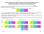
1
Store Your Digital Creations™
SeriTek /SpyderHUB
™
USB 2.0/FireWire to eSATA Converter
User Manual
FirmTek, LLC
www.firmtek.com
Copyright
Copyright © 1998-2008 FirmTek, LLC. All rights reserved. No part of this manual may
be reproduced, translated by any means, photocopied, or transmitted in any form without
the prior written permission of FirmTek.
Trademarks
FirmTek, UltraTek, AV-Tek, SeriTek, SeriTek/SpyderHUB, SpyderHUB, and “Store Your
Digital Creations” names, slogans, and logotypes are trademarks of FirmTek, LLC.
Apple, Macintosh, Power Macintosh, Mac, OS 8, OS 9, OS X, Time Machine, and the
Mac logo are registered trademarks of Apple Computer, Incorporated. The "Built for OS
X" graphic is a registered trademark of Apple Computer, Incorporated, and used under
license. All other manufacturer product names mentioned in this manual are for
identification purposes only and are trademarks or registered trademarks of their
respective owners.
Changes
FirmTek reserves the right to make any changes to product design, specifications, or
details without notice. Actual product photos or screenshots may look different from
those provided.
Notice
The material content of this manual is for informational purposes only. It is possible the
content of this manual may contain technical inaccuracies, omissions, typographical, or
other errors. FirmTek assumes no liability resulting from any such errors, including, but
not limited to loss of data or profits.
Under no circumstances, including, but not limited to, negligence, shall FirmTek, LLC be
liable for any direct, indirect, special, incidental or consequential damage, including, but
not limited to loss of data or profits arising out of the use, or the inability to use the
SeriTek/SpyderHUB, even if FirmTek, LLC or a FirmTek, LLC authorized representative
has been advised of the possibility of such damages. If your use of the
SeriTek/SpyderHUB results in the need for servicing, repair or correction of equipment
or data, you assume all costs and risks thereof.
Before installing SeriTek/SpyderHUB or any other hardware or software, you are
responsible for backing up data contained on any storage devices. After hardware or
software installation, you are responsible for backing up data on any storage devices at
frequent intervals.
Table of Contents
1) Introduction ...................................................................................................................................... 1
Welcome ........................................................................................................................................... 1
About This User Manual ................................................................................................................ 1
About the SeriTek/SpyderHUB..................................................................................................... 1
SpyderHUB Key Features and Benefits ..................................................................................... 1
SeriTek/SpyderHUB Specifications............................................................................................. 1
SeriTek/SpyderHUB Package Contents..................................................................................... 2
2) Getting to Know the SeriTek/SpyderHUB.................................................................................. 3
Overview ........................................................................................................................................... 3
RAID Modes..................................................................................................................................... 3
RAID 0........................................................................................................................................... 3
SPAN............................................................................................................................................. 3
JBOD ............................................................................................................................................. 4
SpyderHUB Front............................................................................................................................ 4
Power LED ................................................................................................................................... 4
Activity 1 LED .............................................................................................................................. 4
Activity 2 LED .............................................................................................................................. 4
Selector Button............................................................................................................................ 5
RAID 0 LED.................................................................................................................................. 5
SPAN LED.................................................................................................................................... 5
JBOD LED.................................................................................................................................... 5
SpyderHUB Back ............................................................................................................................ 5
3) Connecting and Using the SpyderHUB...................................................................................... 6
Power and Port Selection.............................................................................................................. 6
Setting the Disk Mode .................................................................................................................... 7
Connecting eSATA Drives or Enclosures .................................................................................. 8
Daisy-Chaining FireWire (Optional)............................................................................................. 9
4) FAQ: Frequently Asked Questions ........................................................................................... 10
Does the SpyderHUB provide USB to FireWire Connectivity?........................................ 10
Is the SpyderHUB Compatible with Port Multiplier Enclosures? ..................................... 10
Why Won’t Mac OS X Leopard Start Properly When Using USB?................................. 10
Can a SpyderHUB RAID Set be Shared Between a Mac and a PC? ............................ 10
Can the Macintosh Boot from Hard Drives Connected to the SpyderHUB?................. 10
5) Product Support............................................................................................................................ 12
Further Information ....................................................................................................................... 12
Contacting FirmTek ...................................................................................................................... 12
Return Merchandise Authorization ............................................................................................ 12
6) Product Warranty and Disclaimers ........................................................................................... 13
7) Regulatory Compliance Statements ......................................................................................... 13
Federal Communications Commission Radio Frequency Interference Statement.......... 13
CE European Union Compliance Statement ........................................................................... 14
1) Introduction
Welcome
Congratulations and thank you for purchasing the SeriTek/SpyderHUB.
About This User Manual
This user manual was written with the assumption that you are familiar with your
Macintosh or PC, and that you are comfortable with its ports and operation. For further
information, and to get acquainted with your computer, please refer to your computer
user manual.
About the SeriTek/SpyderHUB
The SeriTek/SpyderHUB is an eSATA converter that allows up to two external eSATA
hard drives to interface with a USB or FireWire computer port while supporting hardware
RAID or JBOD modes. The SeriTek/SpyderHUB provides Macintosh boot capabilities
for external eSATA enclosures.
SpyderHUB Key Features and Benefits
•
•
•
•
•
•
•
•
•
•
•
•
•
•
Provides Mac OS boot capability to external eSATA enclosures
Allows content to be shared between different Macintosh and/or PC
Provides FireWire daisy-chaining capability
Operates using computer USB or FireWire bus power (external power adapter
optional)
Expands eSATA direct connect enclosure connectivity to include FireWire
800/400/USB 2.0 host interfaces (FireWire 400 requires optional 400/800
adapter)
Features dual external eSATA ports and a FireWire daisy-chain device port
Includes FireWire 800 and USB 2.0 host input ports
Activity LED for each hard drive
Supports JBOD and hardware RAID 0/stripe and SPAN/concatenate modes
SATA II compliant; auto-negotiates support for the latest 3Gb/s and legacy
1.5Gb/s Serial ATA drives
Attractive design
Features Kensington Security Slot
Easy to set up, easy to transport, compact, lightweight and portable
Platform and Operating system independent; compatible with all Macintosh and
PC computers running Mac OS X, Windows and Linux
SeriTek/SpyderHUB Specifications
•
•
•
•
•
Requires Macintosh or PC with a FireWire 800, 400 or USB 2.0 port
Supports up to two external SATA HDD
Offers RAID 0/Striping, SPAN/concatenate, and JBOD modes
Operating system independent
One year limited parts & labor warranty
1
SeriTek/SpyderHUB Package Contents
•
•
(1) SeriTek/SpyderHUB
(1) User Manual on CD-ROM
2
2) Getting to Know the SeriTek/SpyderHUB
Overview
The SeriTek/SpyderHUB (herein referred to as “SpyderHUB”) is an ultra-small, 4ounce/110-gram device that offers users the ability to connect external eSATA hard
drives and enclosures to their computers, even when their computers do not natively
support eSATA. The SpyderHUB does this by providing USB 2.0 & FireWire to eSATA
connectivity capabilities.
The SpyderHUB supports three types of RAID modes: RAID 0 (Striping), SPAN
(Concatenate), and JBOD (Just a Bunch Of Disks).
RAID Modes
RAID 0
RAID mode 0 is also known as “striping.” A hard drive volume that is striped has its data
broken up and spread across two hard drives. Read/write performance, especially for
sequential access, is improved as the data is read and written across two drives
simultaneously.
If two hard drives are connected to the SpyderHUB and formatted, the drives will be
used simultaneously. For optimal results, the hard drives should be the same size,
model and manufacturer. Using mismatched hard drives will provide slower
performance and may be less reliable. The RAID 0 stripe setting uses two disks of
equal size to create a single striped RAID volume, the size of which will be two times of
the size of the individual hard drives. If equally-sized hard drives are not used, the
formatted volume will be twice the size of the smaller of the two hard drives. Using
identical hard drives is the preferred way to configure a RAID 0 striped set.
Both hard drives formatted as a single RAID 0 volume must always be connected to the
SpyderHUB in order for them to function properly. If a RAID 0 configuration is removed
from the SATA enclosure, the hard drives must be reinstalled in the same order or the
RAID will not be recognized. Writing 1 or 2 on the hard drive labels will help the user
know which bay each hard drive should be placed in.
SPAN
The SPAN mode is also known as the “concatenate” mode. This mode allows two hard
drives to be concatenated, or added, together.
For example, if two 1-terabyte hard drives are connected to the SpyderHUB and
formatted using the SPAN mode, the two hard drives will appear as a single 2-terabyte
logical volume to the computer. Only when the first hard drive fills up with data will the
second hard drive be used.
3
It is not necessary for the hard drives used as a SPAN set to be the same size, model or
manufacturer. However, better performance will be obtained if the hard drives have
similar performance characteristics.
Both hard drives formatted as a single SPAN volume must always be connected to the
SpyderHUB in order for them to function properly. If a SPAN configuration is removed
from the SATA enclosure, the hard drives must be reinstalled in the same order or the
RAID will not be recognized. Writing 1 or 2 on the hard drive labels will help the user
know which bay each hard drive should be placed in.
JBOD
JBOD is an acronym for “Just a Bunch Of Disks.” When a single hard drive is connected
to the SpyderHUB and formatted using the JBOD mode it is recognized by the computer
operating system as a separate independent hard drive. When two hard drives are
connected to the SpyderHUB and formatted using the JBOD mode they are recognized
by the computer operating system as two separate independent hard drives. Unlike the
RAID 0 or SPAN modes, it is not necessary to connect a pair of hard drives to the
SpyderHUB when using the JBOD mode. One or two hard drives can be connected to
the SpyderHUB in JBOD mode, and each one will be recognized independently by the
computer operating system.
SpyderHUB Front
The SpyderHUB LED indicators and mode selector switch are located on the front of the
SpyderHUB.
Power LED
This LED indicates whether the SpyderHUB is provided with power by the computer’s
USB or FireWire port, or by the optional power adapter.
Activity 1 LED
This LED indicates I/O activity for hard drive #1.
Activity 2 LED
This LED indicates I/O activity for hard drive #2.
4
Selector Button
This push-button momentary switch is used to change the RAID modes (RAID 0, SPAN,
or JBOD). This switch must be held down for several seconds for the RAID mode to
change.
RAID 0 LED
This LED indicates that RAID 0 is the current RAID mode.
SPAN LED
This LED indicates that SPAN/concatenate is the current RAID mode.
JBOD LED
This LED indicates that JBOD is the current RAID mode.
SpyderHUB Back
The back of the SpyderHUB contains a power receptacle and one USB, two FireWire
800, and two eSATA connectors.
5
3) Connecting and Using the SpyderHUB
Caution: Prior to installing the SpyderHUB and hard drive(s) or peripheral(s),
please make sure your data is backed up. The SeriTek/SpyderHUB and your computer
contain sensitive components that can be permanently damaged by Static Electric
Discharge. Be sure you are working in an area free of static electricity to prevent them
from being damaged.
Quick Start
1. Connect the FireWire or USB cable to the SpyderHUB.
2. Connect the cable to the computer.
3. Set the SpyderHUB mode to JBOD, RAID 0 or SPAN.
4. Connect the eSATA enclosure and turn it on.
5. If the hard drive has data on it use JBOD mode to mount it. If the hard drive has
not been prepared for the computer erase it. If RAID 0 or the SPAN mode are
selected use Disk Utility to erase the new volume. All data on the SpyderHUB
connected hard disks will be destroyed if erase is completed.
6. DO NOT change the hard drive configuration until the eSATA enclosure is turned
off. Once the drive change is completed the enclosure can be turned back on.
Removing one of the hard disks or inserting a hard disk while the eSATA
enclosure is turned on may cause the computer to become confused and make
the hard disks unusable until the enclosure is turned off for 10 seconds and
turned back on.
7. If a RAID 0 or SPAN configuration is created please remember that the hard
drive placement is important. If you remove the hard drives from the eSATA
enclosure note which bay each hard drive is mounted in. If the hard drives are
reinserted in the wrong bay the SpyderHUB will ask to reinitialize the volume.
Loading the hard drives in the original order will correct the issue.
8. When changing SpyderHUB disk modes dismount the hard drives from the
desktop, turn off the SATA enclosure, set the new mode by holding the middle
button until the light is solid above the new mode. Now disconnect the computer
from the SpyderHUB, wait 10 seconds and then reconnect it. This will reset the
bus. Next, erase the hard drives connected to the SpyderHUB for use with the
new disk mode.
9. While not required, disconnecting the SpyderHUB from the computer when it is
not in use will save electricity and protect it from possible power spikes.
Power and Port Selection
The proper way to setup the SpyderHUB is to connect the SpyderHUB to a FireWire 800
or USB 2.0 cable first and then connect the other end of the data cable to the computer.
To remove the SpyderHUB please disconnect the cable from the computer first. By
following these steps you can reduce the chance of an electrical spike. If you plan to use
6
a FireWire 400 connection you will need a FireWire 800 to FireWire 400 adapter, which
is available separately. The SpyderHUB is powered by the computer’s USB 2.0 port or
FireWire port and requires approximately 3-4 watts for operation. An optional power
adapter is available for situations where the computer’s FireWire or USB port, or external
USB hub, does not provide adequate power. The SpyderHUB usually works well simply
using power provided by the computer’s USB or FireWire port. Maximum hard disk
performance will be achieved when using a FireWire 800 host connection.
Setting the Disk Mode
While the computer is powered, set the disk mode that is desired. Hardware RAID
0/striped, hardware SPAN/concatenate, and JBOD modes are available. Pressing the
front Selector button will allow a new disk mode to be selected. Holding the Selector
button until the light under the new mode blinks 8 times will change the disk mode to the
new setting.
Caution: If the SpyderHUB RAID 0 or SPAN mode is configured, Mac OS X will
ask if the user wants to initialize the hard drive(s). DO NOT choose to erase or
format the volume If you have any existing data that you wish to keep on the individual
eSATA hard drive(s) attached to the SpyderHUB. Back up the data or change the hard
drives first as this process will destroy any data on the SpyderHUB-attached hard drives
when a new hardware RAID volume is created. If you intend to use the hard drives
individually in JBOD mode and you selected RAID 0 or SPAN by mistake, move the
selector back to JBOD. This will protect the data on the hard drive(s) attached to the
SpyderHUB. Accidentally moving the SpyderHUB to different disk modes will not
automatically destroy data. However, if you choose to format the hard drives to create a
new RAID volume, all data will be destroyed when the new RAID 0 or SPAN volume is
created. Most users will select a disk mode and stay with it. However. Please remember
that if you select a new mode the hard drives will need to be reinitialized.
The SpyderHUB includes smart technology that allows the last disk mode selected to be
preserved even when power to the unit has been interrupted. This feature provides the
user with the same disk mode when traveling or during other periods where the unit is
without power.
If the SpyderHUB is used with different hard drive configurations the user will need to
remember the correct setting for each configuration. If a software RAID is utilized or
individual hard drive(s) are attached to the SpyderHUB, the JBOD setting should be
selected. The JBOD setting should be used for most applications except when a
SpyderHUB based Hardware RAID is desired. The SpyderHUB RAID 0/stripe or
SPAN/concatenate modes should only be selected when the user desires to utilize the
FirmTek built-in hardware RAID capability. For more information about the available
SpyderHUB RAID configurations please read the “Getting to Know the
SeriTek/SpyderHUB” section of this manual.
7
Connecting eSATA Drives or Enclosures
Connect up to two external eSATA direct connect hard drives inside the SeriTek/2EN2
enclosure (or another eSATA enclosure) to the SpyderHUB. Turn the enclosure on and
the hard drives will mount on the computer if they are properly initialized. If not, initialize
(erase/format) the hard drives and they will be available for use with the computer. The
image below shows how to erase the hard drives connected to the SpyderHUB with Mac
OS X Disk Utility. Disk Utility can be located at Macintosh
HD>Applications>Utilities>Disk Utility.
Once the hard drives have been formatted they will mount on the computer desktop.
The image above displays how two hard drives in an eSATA enclosure were added to
an Apple Mac Mini.
When a hard drive attached to the top eSATA connector on back of the SpyderHUB is in
use, the Activity 1 LED will blink. A hard drive connected to the bottom eSATA
connector will activate the Activity 2 LED. These LEDs are located to the left of the
SpyderHUB mode selector button.
The SpyderHUB allows an eSATA enclosure to be connected to the computers FireWire
or USB port. This will work well as long as the user does not try to hot swap SATA hard
drives attached to the SpyderHUB while the enclosure(s) is left on. The Apple FireWire
driver does not support multi-drive hot swap in the traditional SATA manner. Instead, the
8
SpyderHUB connected hard drives should be dismounted from the desktop and the
SATA enclosure(s) turned off prior to a hard drive configuration change. Once the
change is completed the SATA enclosure can be turned on and the hard drives will be
recognized. This can be done while the SpyderHUB and the computer are still powered.
Daisy-Chaining FireWire (Optional)
A second FireWire 800 port is available for daisy-chaining additional FireWire devices to
the SpyderHUB. Either FireWire port can be used for the host computer or for daisychaining purposes. As a test, FirmTek was able to configure three hard drives as a Mac
OS X Disk Utility striped RAID set with two eSATA drives connected to the SpyderHUB
in JBOD mode, and one FireWire daisy-chained hard drive. This was a software-based
RAID configuration with Mac OS X providing the striping functionality in the operating
system.
SpyderHUB hardware RAID configurations are limited to the two eSATA hard drives
connected directly to the eSATA ports on the SpyderHUB. A FireWire daisy-chained
hard drive can be mounted separately while the SpyderHUB is configured to support any
of the three RAID modes (RAID 0/SPAN/JBOD) on directly-connected eSATA hard
drives. The daisy-chained FireWire hard drive cannot be part of the SpyderHUB
hardware RAID and will be recognized separately by the computer operating system.
Note to Users Daisy-Chaining FireWire Hard Drives: If a self-powered FireWire hard
drive is connected to the second FireWire daisy-chain port and it is necessary to change
the SpyderHUB RAID mode selection, it will be necessary to completely power down the
SpyderHUB by removing all FireWire or USB cables (and the optional power adapter, if
used). This will clear the SpyderHUB disk configuration settings and allow the new
mode to be accepted. This step is not necessary if a self-powered FireWire hard drive is
NOT connected to the second FireWire daisy-chain port.
9
4) FAQ: Frequently Asked Questions
Does the SpyderHUB provide USB to FireWire Connectivity?
No, the SpyderHUB is a USB or FireWire to eSATA converter. Either USB or FireWire
can be used to access eSATA hard drives. The SpyderHUB will not allow FireWire hard
drives to be recognized via the USB port, or vice-versa.
Is the SpyderHUB Compatible with Port Multiplier Enclosures?
Not officially. While the FirmTek SpyderHUB specifications indicate that SATA PM
enclosures are not supported, the SpyderHUB does provide limited PM support. The
limitation is that the SpyderHUB can only support a maximum of two SATA hard drives.
A PM enclosure with a SiI-5744 PM chip will work with the SpyderHUB using a single
eSATA port and two hard drives in the enclosure. However, if an attempt is made to add
another eSATA hard drive it will exceed the two drive limitation and not mount the hard
drive. In the case of a SeriTek/5PM enclosure, the top two drives in the SeriTek/5PM
will mount along with a “fake” third volume that is really a duplicate of volume #2. While
this may work in an emergency, the use of PM enclosures it is not a supported feature.
Why Won’t Mac OS X Leopard Start Properly When Using USB?
A SpyderHUB connected to the computer using USB can be restarted and the hard
drives will mount properly. However, when using Mac OS X “Leopard” the computer
may not start-up properly when hard drives are attached to the SpyderHUB but not
powered-on. This does not occur with Mac OS X “Tiger,” Windows or with FireWire
connections. The solution is to simply have the hard drives attached and turned on
when using USB and Leopard while starting up the computer.
Can a SpyderHUB RAID Set be Shared Between a Mac and a PC?
The SpyderHUB can be configured with a RAID 0/striped or SPAN/concatenated
hardware RAID set. In our tests, a hardware RAID was created with Mac OS X 10.5
(Leopard) and the volume was partitioned using the Master Boot Record format (The
Master Boot Record format can be selected by using the options button in the Disk Utility
Partition window). With this configuration the resulting RAID volume was able to be
moved between a Macintosh and a Windows XP PC without reformatting the volume.
Apple users should note that Master Boot Record partitions are not currently supported
by Time Machine (http://support.apple.com/kb/TS1550). Note that RAID volumes
formatted using Mac OS X Disk Utility or Windows XP Disk Manager software-based
RAID utilities cannot be shared between Macintosh and PC computers.
Can the Macintosh Boot from Hard Drives Connected to the SpyderHUB?
eSATA hard drives with Mac OS X installed can be booted using the SpyderHUB. A
FireWire connection is bootable on all Macintosh models. A USB host connection is a
bit slower and is bootable with Intel-based Macintosh models. An existing Mac OS X
system can be cloned to the eSATA hard drive using the Disk Utility restore tab,
SuperDuper, or Carbon Copy Cloner. Another method for installing a copy of Mac OS X
10
is to utilize the Apple OS installer DVD. Once Mac OS X is installed the user can boot
from the eSATA hard drive by selecting it in System Preferences>Startup Disk or by
holding the Option key down while restarting the computer.
The image below shows how the Restore tab can be used in Disk Utility to create a
clone of a bootable hard disk. Simply drag the bootable Macintosh hard drive to the
Source field. Now, drag the SpyderHUB empty drive that you want to become a
bootable clone to the Destination field. Click the Restore button and the copy process
begins. If the hard drive attached to the SpyderHUB has data on it the user will want to
use the Mac OS X install disk to create the bootable system.
11
5) Product Support
Further Information
For additional information about the SpyderHUB or for technical assistance, please visit
us at http://www.firmtek.com/support
Contacting FirmTek
Please provide the following information when contacting us:
•
•
•
•
•
•
Product model
Computer model
Operating System type and version (example: Mac OS X, version 10.5)
Hardware and software installed on your system
Contact information including daytime telephone number and email address
A detailed description of the question or problem
Return Merchandise Authorization
If FirmTek technical support determines the product needs to be repaired or replaced, a
Return Merchandise Authorization (RMA) number and shipping address will be provided.
Please pack in the original shipping container with all of the original packaging including the static bag, all hardware, software, cables, and other accessories that may
have come with the original product. You are responsible for shipping and insurance
costs, and any damage incurred due to improper packaging or transport. FirmTek
reserves the right to determine whether the product is to be repaired or replaced with
new or refurbished parts, or with a new or refurbished product. Standard United States
return shipping charges will be paid by FirmTek. Foreign and other shipping methods
such as express shipping are available for an additional charge.
Write down the RMA number on the outside of the shipping container, and include the
following information with the shipment:
•
•
•
•
A description of the problem
A copy of the original purchase invoice
Return shipping address
Contact information including daytime telephone number and email address
FirmTek, LLC reserves the right to refuse shipments missing a valid RMA number.
12
6) Product Warranty and Disclaimers
FirmTek warrants to the original buyer only that this product shall be free from defects in
material and workmanship for a period of 1 year from the original date of purchase. This
warranty is valid only when the original purchase invoice is provided. This warranty shall
not apply to any defects resulting from improper handling, misuse, misapplication,
abuse, or unauthorized modification(s) which are performed by end user.
FirmTek, LLC reserves the right to make changes to any products described in this
manual at any time without notice. FirmTek, LLC assumes no responsibility for the use
or reliability of hardware or software that is not supplied by FirmTek, LLC or its affiliated
companies. FirmTek, LLC does not assume any responsibility or liability arising out of
the application or use of any product described in this document, except as expressly
agreed to in writing by FirmTek, LLC; nor does the purchase or use of a product from
FirmTek, LLC convey a license under any patent rights, copyrights, trademark rights, or
any other intellectual property rights of FirmTek, LLC or third parties.
7) Regulatory Compliance Statements
Federal Communications Commission Radio Frequency Interference
Statement
WARNING: Changes or modifications to this unit not expressly approved by the party
responsible for compliance could void the user’s authority to operate the equipment.
This equipment has been tested and found to comply with the limits for a Class B digital
device, pursuant to Part 15 of the FCC rules. These limits are designed to provide
reasonable protection against harmful interference in a residential installation. This
equipment generates, uses, and can radiate radio frequency energy, and if not installed
and used in accordance with the instruction manual, may cause harmful interference to
radio communications. However, there is no guarantee that interference will not occur in
a particular installation. However, if this equipment does cause interference to radio or
television equipment reception, which can be determined by turning the equipment off
and on, the user is encouraged to try to correct the interference by one or more of the
following measures:
•
•
•
•
•
Reorient or relocate the receiving antenna.
Increase the separation between equipment and receiver.
Connect the equipment to an outlet on a circuit different from that to which the
receiver is connected.
Consult the dealer or an experienced radio/television technician for help.
Use a shielded and properly grounded I/O cable and power cable to ensure
compliance of this unit to the specified limits of the rules.
13
This device complies with part 15 of the FCC rules. Operation is subject to the following
two conditions: (1) this device may not cause harmful interference and (2) this device
must accept any interference received, including interference that may cause undesired
operation.
CE European Union Compliance Statement
EMC compliance:
Emissions:
EN55022: 1998, Class B
Immunity:
EN55024: 1998
EN61000-4-2: 1995+A1: 1998
EN61000-4-3: 1995+A1: 1998
EN61000-4-4: 1995
EN61000-4-6: 1996
EN61000-4-8: 1993
14