1
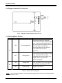
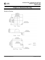
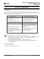
Pyroelectric Infrared PIR Motion
Sensor Detector ADJ
User’s Guide
© 2004-2009 Sure Electronics Inc.
DC-SS502_Ver1.0
PYROELECTRIC INFRARED PIR MOTION
SENSOR DETECTOR ADJ
USER’S GUIDE
Table of Contents
Chapter 1. Overview ..........................................................................................................1
1.1
1.2
Preface ............................................................................................................................ 1
Functions........................................................................................................................ 1
Chapter 2. Hardware Detail ...............................................................................................2
2.1
2.2
2.3
Specifications................................................................................................................. 2
Diagram of Internal Pin J5 and J6 ................................................................................ 3
Switching Mode Options ............................................................................................... 3
Chapter 3. Electrical Characteristics ...............................................................................4
3.1
3.2
3.3
Ratings............................................................................................................................ 4
Diagram of Time Sequence........................................................................................... 4
Detection Range............................................................................................................. 5
Chapter 4. Mechanical Drawing........................................................................................7
Chapter 5. Applications .....................................................................................................8
5.1
5.2
Applications ................................................................................................................... 8
Typical Application ........................................................................................................ 8
Chapter 6. Contact Us .....................................................................................................10
© 2004-2009 Sure Electronics Inc.
DC-SS502_Ver1.0_Page i
Pyroelectric Infrared PIR Motion Sensor Detector ADJ
NOTES:
Product Version
:
Ver 1.1
Document Version
:
Ver 1.0
DC-SS502_Ver1.0_Page ii
© 2004-2009 Sure Electronics Inc.
PYROELECTRIC INFRARED PIR MOTION
SENSOR DETECTOR ADJ
USER’S GUIDE
Chapter 1. Overview
1.1 Preface
Thanks for using infrared pyroelectric detection module by Sure Electronics. This module is delicate
and beautiful yet features impressive reliability. It has a wide range of working voltage, various
working status options and two different control output methods (level pulse output or relay control
output). Its simple-and-easy wiring method and adjustable detection sensitivity helps simplify the
secondary application and it is really your ideal choice.
1.2 Functions
This module consists of a passive infrared pyroelectric sensor (PIR), Phil Neal optical filter and
BISS0001 chip. It can accurately detect any moving object (e.g. human body) within the detection
range and output real-time level signal. It has a preferable sensitivity and broader detection range.
Product Features:
1.
2.
3.
4.
5.
Low noise, high sensitivity and broad detection range, etc.
Wide working supply: DC8V-24V or DC3.3V
Level output & relay control output (@+VCC)
Adjustable sensitivity
Two switching modes are available: Enable LDR/Disable LDR and Retriggerable/
Non-triggerable. Please refer to table 2 for details.
Note:
Never use +VCC and +3.3V simultaneously.
© 2004-2009 Sure Electronics Inc.
DC-SS502_Ver1.0_Page 1
PYROELECTRIC INFRARED PIR MOTION
SENSOR DETECTOR ADJ
USER’S GUIDE
Chapter 2. Hardware Detail
2.1 Specifications
Product’s outline and pinout are shown in fig 1:
Fig 1 Outline and Pinout
Pinout
Name
+3.3V
+VCC
OUTPUT
GND
Relay2
Relay1
Pin number
1
2
3
4
5
6
Table 1
Note:
Function
Power Supply DC 3.3V
Power Supply DC8V-24V
Output pin
GND
Pin 2 of relay
Pin 1 of relay
Diagram of Pins’ Functions
Pin 2, 3 and 4 can be used for connection and users may connect by themselves if other
pins are also required.
DC-SS502_Ver1.0_Page 2
© 2004-2009 Sure Electronics Inc.
Hardware Detail
2.2 Diagram of Internal Pin J5 and J6
Fig 2
Diagram of Inner Structure of J5 and J6
2.3 Switching Mode Options
Switch
Status
Function
ON
Non-retriggerable
OFF
Retriggerable
ON
Enable LDR
OFF
Disable LDR
K1
K2
Note
This module cannot be triggered
continuously during the output of high
level. It can only be triggered when
the module starts outputting low level
after resuming from high level.
Interval between two high levels is
2-3s. Refer to fig 4 for time
sequence.
This module can be triggered
continuously during the output of high
level. The module will not stop
outputting high level until there is no
trigger. Refer to fig 3 for time
sequence diagram.
When ambient light reaches a certain
level, the module will not be triggered
and will keep outputting low level.
Ambient light is irrelevant to the
trigger of the module.
Table 2 Switch Status Diagram
Note:
+V CC should be used to connect power supply when a relay is connected like
shown in fig 2.
© 2004-2009 Sure Electronics Inc.
DC-SS502_Ver1.0_Page 3
PYROELECTRIC INFRARED PIR MOTION
SENSOR DETECTOR ADJ
USER’S GUIDE
Chapter 3. Electrical Characteristics
3.1 Ratings
Symbol
T
+VCC
+3.3V
Vout
Name
Operating Temperature Range
Operating Power Supply1
Operating Power Supply2
Output HIGH Voltage
Rating
0o-60o
DC 8V-24V
DC 3.3V
3.5V(@12V);
3.2V(@3.3V)
I
Working current (No load@12V)
4.7mA.
RL
Load resistor
>600Ω
Tx
Retention time of output high level
10-12 seconds refer to fig 3 and 4
<1>
Ti
Interval between 2 high levels
2-3 seconds refer to fig 3 and 4
<2>
Detection Normal detection range (@ 26 ℃ 3-4m
Range
and maximum sensitivity)
When human moves sideward relative to
Angle of 100o taper
the module, its sensitivity will reach
Detection
highest and will reach lowest when
human moves vertically.
Table 3
Note:
<1>: Work in non-retriggering mode.
<2>: When the module detects any proximity of ambient or human temperature,
the detection distance and sensitivity falls drastically and sometimes the
proximity may cause temporary failure. This failure is not ever lasting and the
circuit will regain its normal working status when the temperature difference
becomes huge.
Note:
Contact us if you need to redefine the range of TX or TI. Sure Electronics will
try its best to serve you and you may refer to chapter 6 for contact info.
3.2 Diagram of Time Sequence
DC-SS502_Ver1.0_Page 4
© 2004-2009 Sure Electronics Inc.
Electrical Characteristics
Fig 3 Retrigerrable Time Sequence Diagram
Fig 4 Non-retrigerrable Time Sequence Diagram
Note:
VS means the high level triggered by human or moving objects in the detection range;
A stands for Retriggerable (High level) or Non-retriggerable (Low level);
VO stands for module output (Vout) and control signal of relay (high level effective).
3.3 Detection Range
The designed detection distance of infrared module is shown in fig 5. The viewing angle of
0
detection range is 100 and sensitivity adjustment is also allowed.
© 2004-2009 Sure Electronics Inc.
DC-SS502_Ver1.0_Page 5
Electrical Characteristics
Fig 5 Diagram of Detection Range
NOTE:
When human moves sideward relative to the module, its sensitivity will reach highest,
and will reach lowest when human moves vertically.
DC-SS502_Ver1.0_Page 6
© 2004-2009 Sure Electronics Inc.
PYROELECTRIC INFRARED PIR MOTION
SENSOR DETECTOR ADJ
USER’S GUIDE
Chapter 4. Mechanical Drawing
Mechanical Drawing
© 2004-2009 Sure Electronics Inc.
DC-SS502_Ver1.0_Page 7
PYROELECTRIC INFRARED PIR MOTION
SENSOR DETECTOR ADJ
USER’S GUIDE
Chapter 5. Applications
5.1 Applications
Infrared module is now a widely accepted product in various applications in society, such as
moving body detection, automatic control, proximity switch, electronic anti-theft, security
protection, remote measure like shown in table 4.
Automatic Control
Electronic Anti-theft, Security
Automatic lamp or automatic door
control in places like public area,
walkway or store.
Auto flushing control in toilet.
Can be used for security
application, such as prevention of human
or animal from breaking into some
important or dangerous area.
Human Body Detection
Miscellaneous
Automatic pedestrian flow count
Note:
This infrared module is especially
suitable for applications in which
pedestrian flow is small and the use of
this module might be affected by some
external factors
When someone is paying a visit,
surveillance devices like monitor will be
enabled automatically or automatic door
bell application.
Automatic shuttering of video camera
or digital camera when human
movement is detected.
Table 4
Note:
This infrared cannot be used in the following environment:
1. Direct exposure under intense sunlight, automobile headlights or incandescent lamp.
2. Places in which air-conditioner, refrigerator or stove exist, which make the
temperature changes drastically.
3. Places in which furniture, obstacles or large-scaled bonsai exist.
4. Never install the infrared module in places that face windows or places in which
strong airflow exists.
5.2 Typical Application
Automatic lamp control like shown in fig 6.
DC-SS502_Ver1.0_Page 8
© 2004-2009 Sure Electronics Inc.
Applications
Fig 6 Diagram of Lamp Automatic Control
Wire the infrared module with relay as per the following steps:
1. Connect pin 2 with +12V DC supply, and pin 4 with the ground.
2. Connect pin 5 and 6 with weak electricity pin of relay
3. Power up the lamp with mains.
Function:
When human movement is detected in the infrared detection range, the module will output a relay
control signal which makes relay work and the lamp is thus illuminated. Over a period of time,
infrared module lowers its output automatically which switch off the relay and consequently, the
lamp is powered off. This infrared can work in either retriggerable or non-retriggerable mode
controlled by switch K1.
When K2 is switched on, this module can be used to control lamps in public walkway. The module
won’t work during daylight time and will be enabled when ambient light weakens and lamps are
thus controlled.
Note:
Recommended installation height 2-3m, to achieve optimum effect, you may adjust the
viewing angle.
© 2004-2009 Sure Electronics Inc.
DC-SS502_Ver1.0_page 9
PYROELECTRIC INFRARED PIR MOTION
SENSOR DETECTOR ADJ
USER’S GUIDE
Chapter 6. Contact Us
Sure Electronics Co., Ltd.
5F, Zone A,
Qinhuai Technology Innovation Center
105-2 DaMing Rd (ZIP:210022)
Nanjing
P.R.China
Tel:
+86-13601408832 (For technical questions only)
+86-25-66606340 (English service, from GMT1-10AM)
Fax:
+86-25- 66606341-866
Website:
www.sure-electronics.com
www.sure-electronics.net
DC-SS502_Ver1.0_Page 10
© 2004-2009 Sure Electronics Inc.