1
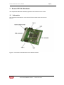
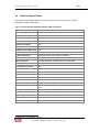
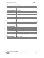
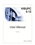
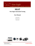
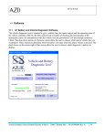
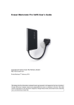
Kvaser PC104+ User's Guide
Copyright 2001-2003 KVASER AB, Mölndal, Sweden
http://www.kvaser.com
Last updated Monday, 13 November 2006 - Printed Monday, 13 November 2006
We believe that the information contained herein was accurate in all respects at the time of
printing. KVASER cannot, however, assume any responsibility for errors or omissions in this
text. Also note that the information in this document is subject to change without notice and
should not be construed as a commitment by KVASER.
Kvaser PC104+ User's Guide
(This page is intentionally left blank.)
Kvaser AB, Mölndal, Sweden — www.kvaser.com
2(17)
Kvaser PC104+ User's Guide
3(17)
1 Table of contents
Kvaser PC104+ User's Guide............................................................................................................ 1
1
Table of contents ......................................................................................................................... 3
2
Introduction................................................................................................................................... 4
2.1
Scope of This Document....................................................................................................... 4
2.2
General Description ............................................................................................................... 5
2.3
PC104+ Features................................................................................................................... 5
3
Kvaser PC104+ Hardware .......................................................................................................... 6
3.1
Schematics ............................................................................................................................. 6
3.2
Technical Specification ......................................................................................................... 7
3.3
Isolated CAN Drivers ............................................................................................................. 9
3.4
Stack-Through Connector..................................................................................................... 9
3.5
Inner and Outer Shield .......................................................................................................... 9
3.6
Protection against over voltage............................................................................................ 9
4
Kvaser PC104+ Installation ..................................................................................................... 10
4.1
Install Hardware ................................................................................................................... 10
4.2
Updated Drivers and Device Firmware............................................................................. 10
4.3
Setting the I/O Address Range .......................................................................................... 10
4.4
Setting the Interrupt ............................................................................................................. 10
4.5
Setting the Board Number Switch ..................................................................................... 11
4.6
The CAN Channels.............................................................................................................. 12
4.7
CAN Bus Termination.......................................................................................................... 14
4.8
LED Indicators ...................................................................................................................... 14
4.9
Motherboard Power Supply................................................................................................ 14
4.10 Do’s and Don’ts .................................................................................................................... 14
5
Software Support....................................................................................................................... 15
6
Legal Information....................................................................................................................... 16
7
Document Revision History ...........................................................................................17
Kvaser AB, Mölndal, Sweden — www.kvaser.com
Kvaser PC104+ User's Guide
4(17)
2 Introduction
Since 1985, Kvaser has turned its full attention towards Controller Area Network and
associated technologies. Based in Sweden, Kvaser develops and manufactures innovative
and high performance PC interfaces for the global market.
2.1
Scope of This Document
This manual is applicable for the following Kvaser products:
1
Product Name
Kvaser PC104+ HS/HS
Product Number
00336-1
Kvaser PC104+ HS/HS
00352-1
1
Description
Two channels CAN interface
with IDC Headers CAN
connectors.
Two channels CAN interface
with DSUB CAN connectors.
The full part numbers 733-0130-nnnnn-n are usually written nnnnn-n. You can use either number when ordering.
Kvaser AB, Mölndal, Sweden — www.kvaser.com
Kvaser PC104+ User's Guide
2.2
5(17)
General Description
The Kvaser PC104+ board is an interface between the PCI bus of a PC/104+ system and the
CAN bus. Compact and self-stacking, it complies with the flexible PC/104-Plus specification.
You can with benefit use several Kvaser PC104+ boards on the same PC/104+ system.
The powerful M16C microcontroller from Renesas, with two built-in CAN controllers, provides
accurate time stamping and high data throughput of CAN messages. Kvaser PC104+
supports 11 bit (CAN 2.0A) as well as 29 bit (CAN 2.0B) identifiers. Remote frames can be
transmitted and received without restrictions. Kvaser PC104+ can detect and generate error
frames on the CAN bus. Kvaser PC104+ offers two completely independent CAN channels
with separate connectors. The CAN bus transceivers are integrated into the device.
Kvaser offers excellent software support. All Kvaser products utilize the common and user
friendly Application Programming Interface, Kvaser CANlib API. It enables you to run any
applications using Kvaser CANlib API on any Kvaser products, without the need of editing the
code and recompile it. Example of supported PCI, PC/104-Plus, USB and PCMCIA interfaces:
•
•
•
•
•
•
•
•
•
•
•
2.3
•
•
•
•
•
•
•
•
•
•
•
•
•
•
•
Kvaser PCIcanx II
Kvaser PCIcanx
Kvaser PC104+
Kvaser PCIcan II
Kvaser PCIcan
Kvaser PCcan
Kvaser Leaf Professional / SemiPro / Light
Kvaser Memorator II
Kvaser Memorator
Kvaser LAPcan II
Kvaser LAPcan
PC104+ Features
PC/104-Plus compliant
Stack-through connector
Communicates with the PC through fast DPRAM
M16C CAN controller from Renesas
High performance on board microcontroller
On board message buffer
CAN 2.0 A and CAN 2.0 B (active)
Supports “Silent Mode”
Two completely independent CAN channels
ISO11898-2 compliant transceivers
DC/DC power supply to galvanically isolated bus drivers – no need for extra external
power supply
High-speed isolator circuits between CAN circuits and CAN drivers
Supports bit rates from 5kbit/s up to 1Mbit/s
Extended temprature range of -40˚ - +85˚
Plug and play installation
Kvaser AB, Mölndal, Sweden — www.kvaser.com
Kvaser PC104+ User's Guide
3 Kvaser PC104+ Hardware
This chapter describes the hardware properties of the Kvaser PC104+ board.
3.1
Schematics
The connectors and switches on the Kvaser PC104+ board are shown below in
Figure 1.
Figure 1: Connectors and switches on the Kvaser PC104+
Kvaser AB, Mölndal, Sweden — www.kvaser.com
6(17)
Kvaser PC104+ User's Guide
3.2
7(17)
Technical Specification
The technical specification for the two product versions of the Kvaser PC104+ board
presented in Table 1 and Table 2.
Table 1. Kvaser PC104+ with IDC Headers CAN connectors.
PC interface
PC/104-Plus.
Stack-through connector
Yes
Voltage Signaling
Supports 5V and 3.3V
Required Supply Voltages 5V and 3.3V
PCI bus rate
32bit, 33MHz
Galvanic Isolation
Yes
Number of CAN channels
2
CAN 2.0A and 2.0B active
Yes
CAN connectors
2 x 10 pin IDC Male Headers.
CAN Transceivers
High Speed CAN, ISO 11898-2 compliant.
CAN Controller
Built into the M16C, ISO 11898-1 compliant.
Microcontroller
Renesas M16C/6N, 256 kB Flash and 10 kB RAM.
Bit rate, CAN bus
5 kbit/s to 1 Mbit/s
Timestamp resolution
1 s
Error Frame Detection
Yes
Error Frame Generation
Yes
Error Counters Reading
Yes
Silent Mode
Yes
Hardware requirements
Industrial computer with a free PC104+ slot.
Power consumption
Approximately 1 W @ 200 mA
Software requirements
2
2
Windows 98, ME, NT 4.0, 2000, XP, or later
Linux
Configuration
Done by software via Plug & Play
Dimensions (W*L)
91 x 96 mm (approx. 3.6 x 3.8 in.)
Operating temperature
-40 ºC ... +85 ºC
Storage temperature
-40 ºC ... +85 ºC
Relative Humidity
0% ... 85% (non condensing.)
Contact us for other operating systems.
Kvaser AB, Mölndal, Sweden — www.kvaser.com
Kvaser PC104+ User's Guide
8(17)
Table 2. Kvaser PC104+ with 9Pin DSUB CAN connectors
PC interface
PC/104-Plus.
Stack-through connector
Yes
Voltage Signaling
Supports 5V and 3.3V
Required Supply Voltages 5V and 3.3V
PCI bus rate
32bit, 33MHz
Galvanic Isolation
Yes
Number of CAN channels
2
CAN 2.0A and 2.0B active
Yes
CAN connectors
2 x 9pin DSUB
CAN Transceivers
High Speed CAN, ISO 11898-2 compliant.
CAN Controller
Built into the M16C, ISO 11898-1 compliant.
Microcontroller
Renesas M16C/6N, 256 kB Flash and 10 kB RAM.
Bit rate, CAN bus
5 kbit/s to 1 Mbit/s
Timestamp resolution
1 s
Error Frame Detection
Yes
Error Frame Generation
Yes
Error Counters Reading
Yes
Silent Mode
Yes
Hardware requirements
Industrial computer with a free PC104+ slot.
Power consumption
Approximately 1 W @ 200 mA
Software requirements
3
3
Windows 98, ME, NT 4.0, 2000, XP, or later
Linux
Configuration
Done by software via Plug & Play
Dimensions (W*L)
91 x 96 mm (approx. 3.6 x 3.8 in.)
Operating temperature
-40 ºC ... +85 ºC
Storage temperature
-40 ºC ... +85 ºC
Relative Humidity
0% ... 85% (non condensing.)
Contact us for other operating systems.
Kvaser AB, Mölndal, Sweden — www.kvaser.com
Kvaser PC104+ User's Guide
3.3
9(17)
Isolated CAN Drivers
Each CAN transceiver is isolated from the CAN controller and all other CAN transceivers. The
CAN driver will get the necessary power from the PCI bus via an isolated DC/DC convert. The
isolation between the CAN controller and the CAN transceiver has a delay of maximum 50 ns
in each direction. This will reduce the possible cable length with 20 meter compared to having
no isolation.
3.4
Stack-Through Connector
The PC/104-Plus specification establishes a standard for the use of a high speed PCI bus in
embedded applications. The Kvaser PC104+ modules are self-stacking and do not require a
card cage or other interconnect support. In addition, the modules are also stackable with
standard PC/104 modules.
3.5
Inner and Outer Shield
There are two shield connections to this board: the inner and outer shield, see chapter 3.6.
The inner shield, pin 5 at DSUB and pin 9 at IDC, is the EMC filter shield ground. This shield
ground must be kept within +/- 50 Volt from CAN GND. If the CAN GND have a voltage above
+/- 30 Volt the inner shield will CAN GND and inner shield be shorted together. For EMC
performance it is best if inner shield and CAN GND is shorted together. The reason to keep
them separated is to make it possible to have inner shield connected to the metallic cover of
the electronic device and still have CAN GND floating, but limited to +/- 30 Volt from the
shield.
The outer shield is the normal shield that should be connected to the shield of the CAN bus
cable. It is connected to IDC pin 10. The intention is then to connect this wire to the DSUB
metallic housing at the entrance in the metallic housing or the cable shield at the external
connector. For the boards with DSUB CAN connectors, this outer shield is connected to the
metal housing of the DSUB. The outer shield can have a voltage +/- 540 Volt from CAN GND
and +/- 270 Volt from internal ground. If the voltage increase above those levels will the
current flow increase up to 200 ampere. There is no current limit, so high current energies will
burn away a component or the wire. ESD and high voltage noise will by this function be
discharged to ground and prevent users from getting sparks when touching the isolated wires.
Inner shield is AC shorted to outer shield via a 10 nF capacitor. Also the outer shield is ACshorted to internal ground. This will reduce the slew rate in the change of the CAN GND level
relative to internal ground.
3.6
Protection against over voltage
The CAN bus interface do have a protection against over voltage at the CANH and CANL
signals. If the voltage will increase above 28 Volt will there be a current flow from CANH and
CANL to ground. An increased voltage level will cause the CANH and CANL to be shorted to
ground and the current flow can increase to 100 ampere or more. The current flow will after a
few milliseconds be reduced to 200 mA. The same is true if there is an over voltage between
CANH and CANL. This part will prevent the CAN bus driver interface to break down due to
ESD, sparks and shortcut to power supply. A continues over voltage at the interface will break
down the protection device. It is the energy that breaks down the device. 30 kV during 10
microseconds is less damaging than 32 Volt over few seconds.
Kvaser AB, Mölndal, Sweden — www.kvaser.com
Kvaser PC104+ User's Guide
10(17)
4 Kvaser PC104+ Installation
For easy installation, all Kvaser PC104+ boards are Plug & Play. For best results, install the
device drivers first. Follow the instructions on the Kvaser CD to do so. Important – you must
read this entire chapter before installing your Kvaser PC104+ board.
4.1
Install Hardware
For driver installation and firmware update, see the driver installation documentation on the
Kvaser CD. To install the hardware, follow these steps:
•
•
•
•
•
4.2
Power down the computer.
For your personal safety, unplug the computer from mains.
Touch the metal chassis of the computer before you remove the Kvaser PC104+ from
its protective antistatic plastic bag.
Insert the board anywhere in a PC/104-Plus stack.
Power up the computer.
Updated Drivers and Device Firmware
Updated drivers and device firmware is available from our web site, http://www.kvaser.com.
4.3
Setting the I/O Address Range
The computer’s BIOS is responsible for allocating an address range for use by the card. This
is normally done when the computer starts. The address range can normally not be adjusted.
4.4
Setting the Interrupt
The computer’s BIOS is responsible for allocating the interrupt vector. Normally you can’t
change this allocation, although some computer BIOS’s will let you do so.
Note that it is perfectly normal for PCI devices to share a single interrupt in the PC. Kvaser
PC104+ will work without problems when sharing the interrupt with other PCI devices.
Kvaser AB, Mölndal, Sweden — www.kvaser.com
Kvaser PC104+ User's Guide
4.5
11(17)
Setting the Board Number Switch
You can stack up to four Kvaser PC104+ devices on a PC/104 system, but each board must
have a unique slot address. The board number switch for that purpose, see Figure 2. This
switch can be set to 0, 1, 2 and 3 programming the board to be located at slot 1, 2, 3 or 4
respectively. Do not use the other switch values. The physical location of the board in the
stack does not matter; the slot number is given by the board number switch, and every board
connected must have a unique slot number compared to all other installed boards.
Figure 2: The board number switch.
Kvaser AB, Mölndal, Sweden — www.kvaser.com
Kvaser PC104+ User's Guide
4.6
12(17)
The CAN Channels
The Kvaser PC104+ has two independent CAN channels located as seen in Figure 1.
Figure 3: One of the CAN connectors on a PC104+ HS/HS board with IDC male headers.
Depending on product variant, the CAN channels have either 10 pin IDC male header
connectors, as seen in Figure 3, or 9 pin DSUB connectors.
4.6.1
10 pin IDC Male Header Connector
The pin numbering of the IDC male header is seen in Figure 4 (when viewed as in Figure 3)
and the functions of the pins are listed in Table 3 below. The pin numbering is chosen so you
can use DSUB connectors by mounting them (the IDC type) on a piece of flat ribbon cable
and connect to the Kvaser PC104+ board.
9
10
7
8
5
3
1
6
4
2
Figure 4. The IDC connector pin numbers on a CAN channel.
Kvaser AB, Mölndal, Sweden — www.kvaser.com
Kvaser PC104+ User's Guide
13(17)
Table 3. Functions of the pins in the IDC Male Header CAN connector.
IDC header pin number
Function
1
Not connected.
2
Not connected.
3
CAN_L
4
CAN_H
5
GND
6
Not connected.
7
Not connected.
8
Not connected.
9
Inner Shield, read chapter 2.6
10
Outer Shield, read chapter 2.6
4.6.2
9 Pin DSUB Connector
The DSUB pin numbering on a CAN channel is shown in Figure 5 and the functions of the
pins are listed in Table 4. Please note that the outer shield is connected to the metal housing
for the DSUB CAN connector.
Figure 5. The DSUB connector pin on a CAN channel.
Table 4. Functions of the pins in the DSUB CAN connector
DSUB pin number
Function
1
Not connected.
2
CAN_L
3
GND
4
Not connected.
5
Inner Shield, read chapter 2.6
6
Not connected.
7
CAN_H
8
Not connected.
9
Not connected.
Metal housing
Outer Shield, read chapter 2.6
Kvaser AB, Mölndal, Sweden — www.kvaser.com
Kvaser PC104+ User's Guide
4.7
14(17)
CAN Bus Termination
There are no on board CAN bus terminators on the PC104+ board. You must terminate the
CAN bus yourself by placing a 120 Ohms resistor between CAN_H and CAN_L at each end
of the CAN bus.
Note that without terminators on the CAN bus, the communication may or may not work – it’s
totally unpredictable. For laboratory use the termination need not be perfect but you will
always need some load resistance between CAN_H and CAN_L somewhere on the CAN bus.
4.8
LED Indicators
The on board LEDs indicate the status of the card according to Table 5. For the LED’s
position on the board, see Figure 1.
Table 5. Meaning of the LED activity on the PC104+ boards.
LED Activity
Both LEDs are blinking continuously with a
frequency of around 5 Hz
Meaning of LED Activity
The built-in self-test failed.
Steady light
The card is OK.
Blinking irregularly
The card is OK, and there is activity (transmit
or receive) on the CAN bus.
4.9
Motherboard Power Supply
The PCI standard mandates that if a PCI connector on the computer motherboard provides
5V, it must also provide 3.3V. However, not all computers follow the standard here. If your
Kvaser PC104+ board is not responding after installation, it could be a good idea to check the
computer documentation if the PCI slots really are compliant to the PCI standard.
4.10 Do’s and Don’ts
Do connect the ground pin on the D-SUB to the ground of your CAN bus.
In case of trouble, do verify that you have at least one terminator on the CAN bus.
Kvaser AB, Mölndal, Sweden — www.kvaser.com
Kvaser PC104+ User's Guide
15(17)
5 Software Support
The Kvaser PC104+ boards are supported by drivers routines and program examples for
4
Windows 95/98/ME, Windows NT/2000/XP, Linux, etc . The software and its documentation
are available from our web site, and not further documented here. Kvaser CANKing - a freeof-charge and general-purpose interactive CAN bus monitor can be download from our web
site.
Please visit our homepage http://www.kvaser.com to find software updates, hints and tips and
other helpful information. You are always welcome to contact our Support Team [email protected].
4
Contact us for other operating systems.
Kvaser AB, Mölndal, Sweden — www.kvaser.com
Kvaser PC104+ User's Guide
16(17)
6 Legal Information
This document must not be copied without our written permission, and the contents thereof
must not be imparted to a third party nor be used for any unauthorized purpose.
Contravention will be prosecuted. We believe that the information contained herein was
accurate in all respects at the time of printing. Kvaser AB cannot, however, assume any
responsibility for errors or omissions in this text. Also note that the information in this
document is subject to change without notice and should not be construed as a commitment
by Kvaser AB.
CE Marking Directive
This line of products has been CE marked. We will be pleased to inform you on which
standards this equipment has been tested for compliance.
RoHS Directive
This line of products will comply with the RoHS (Restriction of Hazardous Substances)
directive when it becomes effective 1 of July 2006. Note that the usage of a product affects its
need to follow the directive.
WEEE Directive
Kvaser will fulfill the national laws as interpreted from the WEEE (Waste Electrical and
Electronic Equipment) directive.
NOTE
This equipment has been tested and found to comply with the limits for a Class A digital
device, pursuant to Part 15 of the FCC Rules. These limits are designed to provide
reasonable protection against harmful interference when the equipment is operated in a
commercial environment. This equipment generates, uses, and can radiate radio frequency
energy and, if not installed and used in accordance with the instruction manual, may cause
harmful interference to radio communications. Operation of this equipment in a residential
area is likely to cause harmful interference in which case the user will be required to correct
the interference at his own expense.
Kvaser AB, Mölndal, Sweden — www.kvaser.com
Kvaser PC104+ User's Guide
17(17)
7 Document Revision History
Date
20051125
20060321
20060323
20060413
20061109
Version
1
2
3
4
5
Changes
Initial edition
Reviewed for release.
Released
Chapter 2 and 3 expanded and corrected
Reviewed – no major changes.
Kvaser AB, Mölndal, Sweden — www.kvaser.com