1
ML-501 Fax Multi Line
INSTALLATION MANUAL
Applied Machines: C353/C253/C203
COLOR MFP (Color/B&W): 35 ppm/35 ppm, 25 ppm/25 ppm, 20 ppm/20 ppm
Product Code: A02E
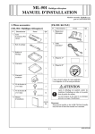
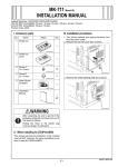
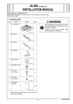
I. Accessory parts
[Fax Kit]
[Fax multi line]
No.
No.
Name
Shape
Name
Shape
Q’ty
1. FAX kit
Q’ty
1. PCI expansion
board (2nd)
1
1
4037IXC118DA
4037IXC073DA
2. Modular cable*
2. Guide rail
2
1
4037IXC074DB
3. Shield box
4442U015AA
1
3. Label A*
1
4037IXC075DB
4. Cover
4. Label B*
1
1
4037IXC076DA
5. Modular cover
4037IXC226DA
5. Installation
precautions
1
4037IXC077DA
1
6. Plate spring
4
* Varies depending on the applicable marketing
area
* Label A and B are not used.
A00JIXC142DA
7. Screw A
(3 × 8 mm)
2
4037IXC138DA
8. Screw B
(3 × 8 mm)
12
After unpacking, be sure to get rid of the
packaging materials and keep them out of
the reach of children.
4037IXC137DA
9. Screw C
(3 × 6 mm)
12
Putting the head in the plastic bag
involves danger of suffocation.
A090IXC001DA
10. Installation
manual
Note:
To install this Kit, the MK-711 (mount kit) must first
be installed on the machine.
1 set
4980IXC019DA
E-1
A02E-9961-00
II. Installation procedures
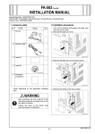
4. Mount the guide rail (two positions) to the shield
box.
1. Turn off the machine and unplug the power cord
from the power outlet.
2. Remove protective tape and shipping materials
and take out accessory parts.
4037IXC142DC
4037IXC079DB
5. Set the SW2 on the FAX controller board to
“LINE-2.”
A02EIXC092DA
3. Mount the PCI expansion board (2nd) to the
shield box using the long driver (two screw A’s
furnished with the kit).
4037IXC572DB
6. Insert the FAX kit and tighten the two shoulder
screws.
Note:
When inserting the board, align it with the slits.
4037IXC078DB
4037IXC081DB
E-2
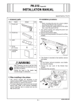
7. Install the cover (six screw B’s furnished with the
kit).
10. Remove the metal blanking plate (four screws).
A02EIXC067DA
4037IXC082DC
11. Mount the plate spring at four positions as illustrated (three screw C’s each, furnished with the
kit).
8. Set the modular cover to the modular jack (TEL).
4037IXC296DA
A02EIXC068DA
9. Remove the shield box cover (four screws).
12. Mount the Fax multi line unit to the rear side of
the machine.
(1) Insert the claw (one position) on the Fax multi
line unit to the mounting hole on the machine.
(2) Attach the connector on the PCI expansion
board (2nd) with the connector on the PCI
expansion board.
(3) Fix the Fax multi line unit to the machine (six
screw B’s furnished with the kit).
A0DCIXC007DA
A02EIXC069DB
E-3
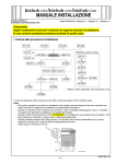
III. Setting the FAX
13. Remove the cover shown in the illustration from
the shield box cover (two screws).
1. Plug the power cord into the power outlet and
turn on the machine.
2. Display the Service Mode screen.
(For details of how to display the Service Mode
screen, see the service manual.)
3. Touch “System 2.”
A02EIXC070DA
14. Install the shield box cover (four screws).
A00JIXE118DA
4. Touch “Option Board Status.”
A02EIXC071DA
15. Connect the modular cable.
Note:
Plug the modular connector into the modular jack
(LINE).
A02EIXE062DA
5. Touch “Set” of FAX (circuit 2).
A02EIXC072DA
A00JIXE128DA
6. Touch “END.”
E-4
12. Touch “Yes.”
7. Touch “FAX.”
A00JIXE118DA
A00JIXE132DA
13. Touch “END.”
14. Touch “Exit” on the Service Mode screen.
15. Turn OFF and ON the Main Power Switch.
Note:
When displayed the Service Mode screen, be sure
to turn off the main power after exiting the Service
Mode screen and wait for 10 seconds or more
before turning on.
8. Touch “Line2.”
9. Touch “Initialization.”
16. Perform the sending and receiving tests
between the Machine and either the store which
offers the service or the local retailer, to check
that it can be operated normally.
A00JIXE129DA
10. Touch “Fax Function Parameter.”
A00JIXE130DA
11. Touch “Yes.”
A00JIXE131DA
E-5
IV. Caution when performing dial transfer
6. Touch “OFF” of Dial Tone Detection.
After setting the country code, dialing operations
may be selected after the switchboard dial tone is
detected depending on the destination. In this case,
depending on the switchboard connected to the
machine and the type of dial tone received from the
switchboard, dialing operations may not be available. If that happens, you may be able to avoid the
problem with the following setting.
<Turn the Dial Tone Detection function OFF>
1. Display the Service Mode screen.
(For details of how to display the Service Mode
screen, see the service manual.)
2. Touch “FAX.”
A00JIXE127DA
7. Touch “END.”
8. Touch “Exit” on the Service Mode screen.
9. Turn OFF and ON the Main Power Switch.
Note:
When displayed the Service Mode screen, be sure
to turn off the main power after exiting the Service
Mode screen and wait for 10 seconds or more
before turning on.
A00JIXE118DA
3. Touch “Line2.”
4. Touch “NetWork.”
A00JIXE129DA
5. Touch “Network Setting 2.”
A00JIXE126DA
E-6